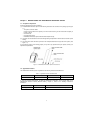
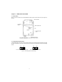
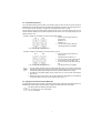
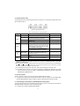
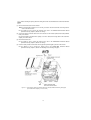
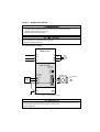
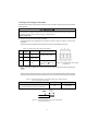
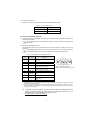
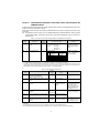
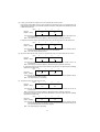
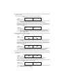
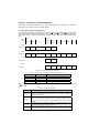
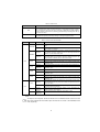
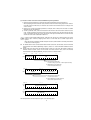
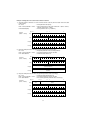
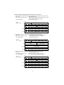
1
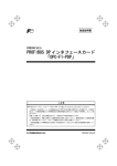
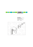
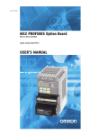
Instruction Manual
PROFIBUS DP Interface Option
"OPC-E1-PDP"
Thank you for purchasing our PROFIBUS DP Interface Option OPC-E1-PDP.
• This product is designed to connect the FRENIC-Multi series of inverters to PROFIBUS DP
Communications Network. Read through this instruction manual and be familiar with the handling
procedure for correct use.
• Improper handling blocks correct operation or causes a short life or failure.
• Deliver this manual to the end user of the product. The end user should keep this manual in a safe place
until the PROFIBUS DP Interface Option is discarded.
• For the usage of inverters, refer to the instruction manual prepared for the FRENIC-Multi series of inverters.
Fuji Electric FA Components & Systems Co., Ltd.
Copyright © 2007 Fuji Electric FA Components & Systems Co., Ltd.
All rights reserved.
No part of this publication may be reproduced or copied without prior written permission from Fuji Electric FA
Components & Systems Co., Ltd.
All products and company names mentioned in this manual are trademarks or registered trademarks of their
respective holders.
The information contained herein is subject to change without prior notice for improvement.
Preface
Thank you for purchasing our PROFIBUS DP Interface Option OPC-E1-PDP.
This manual has been prepared to help you connect your FRENIC-Multi to a PROFIBUS DP master (Siemens
PLC, computer, etc.) via PROFIBUS DP.
Mounting this option on your FRENIC-Multi allows you to connect the FRENIC-Multi to a PROFIBUS DP master
node and control it as a slave unit using run and frequency commands, and access to function codes.
This option has the following features:
• PROFIBUS version:
DP-V0 compliant
• Transmission speed: 9.6 Kbps to 12 Mbps
• Maximum network cable length per segment: 100 m (12 Mbps) to 1200 m (9.6 Kbps)
• Applicable Profile:
PROFIBUS V2 compliant
• Able to read and write all function codes supported in FRENIC-Multi
This instruction manual does not contain inverter handling instructions. Read through this instruction manual in
conjunction with the FRENIC-Multi Instruction Manual (INR-SI47-1094-E) and be familiar with proper handling
and operation of this product. Improper handling might result in incorrect operation, a short life, or even a failure of
this product.
Keep this manual in a safe place.
Related Publications
Listed below are the other materials related to the use of the PROFIBUS DP Interface Option OPC-E1-PDP. Read
them in conjunction with this manual as necessary.
• RS-485 Communication User's Manual
(MEH448)
• FRENIC-Multi Instruction Manual
(INR-SI47-1094-E)
The materials are subject to change without notice. Be sure to obtain the latest editions for use.
Safety precautions
Read this manual thoroughly before proceeding with installation, connections (wiring), operation, or maintenance
and inspection. Ensure you have sound knowledge of the device and familiarize yourself with all safety
information and precautions before proceeding to operate the inverter.
Safety precautions are classified into the following two categories in this manual.
Failure to heed the information indicated by this symbol may lead to
dangerous conditions, possibly resulting in death or serious bodily injuries.
Failure to heed the information indicated by this symbol may lead to
dangerous conditions, possibly resulting in minor or light bodily injuries
and/or substantial property damage.
Failure to heed the information contained under the CAUTION title can also result in serious consequences.
These safety precautions are of utmost importance and must be observed at all times.
1
Installation and wiring
• Turn the inverter's power OFF and wait at least five minutes. Further, check that the DC link bus
voltage between the P (+) and N (-) terminals is lower than 25 VDC.
• Qualified electricians should carry out wiring.
Otherwise, electric shock could occur.
• Do not use the products that are damaged or lacking parts.
Doing so could cause a fire, accident, or injury.
• Prevent lint, paper fibers, sawdust, dust, metallic chips, or other foreign materials from getting into the
inverter and the option.
Otherwise, a fire or an accident might result.
• Incorrect handling in installation/removal jobs could cause a failure.
A failure might result.
• Noise may be emitted from the inverter, motor and wires. Implement appropriate measure to prevent
the nearby sensors and devices from malfunctioning due to such noise.
Otherwise, an accident could occur.
Operation
• Be sure to mount the inverter's and option's terminal covers before turning the inverter's power ON. Do
not remove the covers while power is applied.
Otherwise electric shock could occur.
• Do not operate switches with wet hands.
Doing so could cause electric shock.
• If you configure the function codes wrongly or without completely understanding FRENIC-Multi
Instruction Manual (INR-SI47-1094-E) and the FRENIC-Multi User's Manual (MEH457), the motor may
rotate with a torque or at a speed not permitted for the machine. Confirm and adjust the setting of the
function codes before running the inverter.
Otherwise, an accident could occur.
Maintenance and inspection, and parts replacement
• Turn the inverter's power OFF and wait at least five minutes before starting inspection. Further, check
that the DC link bus voltage between the P (+) and N (-) terminals is lower than 25 VDC.
Otherwise, electric shock could occur.
• Maintenance, inspection, and parts replacement should be made only by qualified persons.
• Take off the watch, rings and other metallic objects before starting work.
• Use insulated tools.
Otherwise, electric shock or injuries could occur.
2
Disposal
• Treat the product as an industrial waste when disposing of it.
Otherwise injuries could occur.
Others
• Never attempt to modify the product.
Doing so could cause electric shock or injuries.
How this manual is organized
This manual is made up of chapters 1 through 12.
Chapter 1 BEFORE USING THE PROFIBUS DP INTERFACE OPTION
Lists points to be checked upon delivery of this option and describes the applicable inverters.
Chapter 2 NAMES AND FUNCTIONS
Shows the part names of this option and describes the terminating resistor switch, node address switches, and
status indicator LEDs.
Chapter 3 MOUNTING THE PROFIBUS DP INTERFACE OPTION
Provides instructions and precautions for mounting this option.
Chapter 4 WIRING AND CABLING
Provides wiring instructions around the terminal blocks on this option and the cable specifications.
Chapter 5 CONFIGURING INVERTER'S FUNCTION CODES FOR PROFIBUS DP COMMUNICATION
Describes the inverter's function codes to be set for the PROFIBUS DP communications link. Also this chapter
lists the related function codes.
Chapter 6 ESTABLISHING A PROFIBUS COMMUNICATIONS LINK
Guides you to establish a PROFIBUS DP communications link between the PROFIBUS DP master node and this
option (slave node).
Chapter 7 QUICK SETUP GUIDE FOR RUNNING THE INVERTER
Describes a simple profile (data format) dedicated to inverter’s run and frequency commands, taking the actual
data transaction data as an example.
Chapter 8 DETAILS OF PROFIBUS DP PROFILES
Details PROFIBUS DP profile data formats and parameters supported by this option. Furthermore, this chapter
describes how the master node accesses inverter’s function codes.
Chapter 9 INVERTER REACTION TO PROFIBUS COMMUNICATIONS ERRORS
Describes on how the inverter operates if a PROFIBUS communications error occurs.
Chapter 10 LIST OF INVERTER ALARM CODES
Lists and explains inverter’s alarm codes.
Chapter 11 TROUBLESHOOTING
Provides troubleshooting instructions for certain problems, e.g., when the inverter does not operate as ordered or
when an alarm condition has been recognized.
Chapter 12 SPECIFICATIONS
Lists the general specifications and communications specifications.
3
Icons
The following icons are used throughout this manual.
This icon indicates information which, if not heeded, can result in the product not operating to full
efficiency, as well as information concerning incorrect operations and settings which can result in
accidents.
This icon indicates information that can prove handy when performing certain settings or operations.
!
This icon indicates a reference to more detailed information.
Table of Contents
Chapter 5 CONFIGURING INVERTER'S FUNCTION
CODES FOR PROFIBUS DP
COMMUNICATION ......................................... 17
Chapter 6 ESTABLISHING A PROFIBUS
COMMUNICATIONS LINK .............................. 18
Chapter 7 QUICK SETUP GUIDE FOR RUNNING THE
INVERTER ...................................................... 19
7.1 Before Proceeding to Data Exchange..................... 19
7.2 Data Transaction Examples in Running an Inverter 19
Chapter 8 DETAILS OF PROFIBUS PROFILES.............. 22
8.1 Description of PPO Types Supported ..................... 22
8.2 PCD Word Area ...................................................... 24
8.3 PCV Word Area ...................................................... 29
Chapter 9 INVERTER REACTION TO PROFIBUS
COMMUNICATIONS ERRORS....................... 36
Chapter 10 LIST OF INVERTER ALARM CODES ............. 37
Chapter 11 TROUBLESHOOTING .................................... 38
Chapter 12 SPECIFICATIONS........................................... 39
12.1 General Specifications ............................................ 39
12.2 Communications Specifications .............................. 39
Preface
...................................................................... 1
How this manual is organized .............................................. 1
Chapter 1 BEFORE USING THE PROFIBUS DP
INTERFACE OPTION ....................................... 5
1.1 Acceptance Inspection.............................................. 5
1.2 Applicable Inverters .................................................. 5
Chapter 2 NAMES AND FUNCTIONS ............................... 6
2.1 Parts Names ............................................................. 6
2.2 Terminating Resistor Switch ..................................... 6
2.3 Node Address Switches............................................ 7
2.4 Setting the Transmission Speed (Baud rate) ............ 7
2.5 Status Indicator LEDs ............................................... 8
2.6 RJ-45 Connector....................................................... 8
2.7 Power Supply Terminal Block and PROFIBUS DP
Terminal Block .......................................................... 8
Chapter 3 MOUNTING THE PROFIBUS DP INTERFACE
OPTION ............................................................ 9
Chapter 4 WIRING AND CABLING.................................. 13
4.1 Basic Connection Diagram ..................................... 13
4.2 Wiring for Power Supply Terminal Block ................. 14
4.3 Wiring for PROFIBUS Connector............................ 15
4.4 ON/OFF Timing of the Option and the Inverter ....... 16
4
Chapter 1
BEFORE USING THE PROFIBUS DP INTERFACE OPTION
1.1 Acceptance Inspection
Unpack the package and check the following:
(1) A PROFIBUS DP interface option and the following accessories are contained in the package. (See Figure
1.1.)
- Two option connection cables
(A short one for inverters with a capacity of 3.7 kW or below and a long one for inverters with a capacity of
5.5 kW or above)
- One ferrite core
- One option fixing screw
- PROFIBUS DP Interface Option Instruction Manual (this manual)
(2) The option and accessories have not been damaged during transportation—there should be no dents or parts
missing.
(3) The model name "OPC-E1-PDP" is printed on the nameplate attached to the right side of the option. (See
Figure 1.1.)
If you suspect the product is not working properly or if you have any questions about your product, contact your
Fuji Electric representative.
Figure 1.1 PROFIBUS DP Interface Option and Accessories
1.2 Applicable Inverters
The PROFIBUS DP interface option is applicable to the following inverters and ROM version.
Table 1.1 Applicable Inverters and ROM Version
Series
Inverter type
Applicable motor rating
ROM version
FRENIC-Multi
FRN"""E1"-"""
All capacities
Version 0700 or later
To check the inverter's ROM version, use Menu #5 "Maintenance Information" on the keypad. (Refer to the
FRENIC-Multi Instruction Manual (INR-SI47-1094-E), Chapter 3, Section 3.4.6 "Reading maintenance
information."
Display on LED Monitor
!"#$
Item
Inverter's ROM version
Description
Shows the inverter's ROM version as a 4-digit code.
5
Chapter 2
NAMES AND FUNCTIONS
2.1 Parts Names
Figure 2.1 shows the inside view of the PROFIBUS DP interface option with its terminal cover (See Figure 3.3)
removed.
Figure 2.1 Parts Names of PROFIBUS DP Interface Option
2.2 Terminating Resistor Switch
The PROFIBUS DP communications network requires insertion of line terminating resistors at its both ends. When
this option is mounted on the inverter at either end of the network, turn this switch ON to insert the terminating
resistor.
ON
OFF
ON
OFF: No insertion of terminating resistor
OFF
ON: Insertion of terminating resistor
Figure 2.2 Terminating Resistor Switch Settings
6
2.3 Node Address Switches
The node address switches (SW1 and SW2) on the interface option are rotary ones that are used to specify the
PROFIBUS DP communications network node address (station address) of the option. The setting range is from 0
to 99 in decimal. The SW1 specifies a 10s digit of the node address and the SW2, a 1s digit.
The node address can also be specified with the inverter's function code o31. The setting range is from 0 to 125 in
decimal. Note that validating the node address specified with the function code o31 requires setting the node
address switches to "00."
Example 1: Setting the node address 27 using the node address switches
SW1
1. When the inverter and this option are
powered OFF:
SW2
Set SW1 to "2."
Set SW2 to "7."
2. Turn the inverter and this option ON.
The setting procedure is completed.
Figure 2.3 Node Address Setting Example 1
Example 2: Setting the node address 125 using the function code o31
SW1
1. When the inverter and this option are
powered OFF:
SW2
Set both the SW1 and SW2 to "0."
2. Turn the inverter and this option ON and
set the function code o31 data to "125."
3. Turn the inverter and this option OFF and
ON.
Figure 2.4 Node Address Setting Example 2
The setting procedure is completed.
1. The node address switches should be accessed with all the power to the inverter and this option
(including the auxiliary power) being OFF. Setting these switches with the power to the inverter and
this option being ON requires turning the power OFF and ON to validate the new setting.
2. To validate the node address setting using the function code o31, turn the inverter and this option
OFF and ON.
3. Setting the function code o31 data to "126" or greater will cause a data setting error. The ERR LED
on the option blinks in red and the inverter issues the alarm code %& .
2.4 Setting the Transmission Speed (Baud rate)
No transmission speed setting is required on the interface option (slave). Setting the transmission speed in the
PROFIBUS DP network master node automatically configures the transmission speed of this option.
This option supports the following transmission speed.
9.6, 19.2, 45.45, 93.75, 187.5, and 500 Kbps
1.5, 3, 6, and 12 Mbps
7
2.5 Status Indicator LEDs
This interface option has four status indicator LEDs shown in Figure 2.5. They indicate the operation status of the
option as listed in Table 2.1.
Figure 2.5 Status Indicator LEDs
Table 2.1 LED Indications and Operation Status
Name
Color
Normal
Blinks in green
Self-diagnostic test running or initialization in This test takes approx. 0.5
progress during powering on sequence
second.
---
Blinks in red
PROFIBUS communications error
The inverter shows %& . *1
Lights in red
Hardware error
(Option not properly installed or option faulty)
The inverter shows %&#.
Wrong configuration of PROFIBUS protocol
(Discrepancy between PPO type defined by the
inverter's function code o30 and the one defined
in the PROFIBUS master node)*2
---
Wrong configuration of PROFIBUS protocol
(The node address is set to 126 or greater.)
The inverter shows %& . *1
Online
(The option communicates normally on the
PROFIBUS network.)
---
OFF
Not online
---
Lights in red
Offline
(The option is not connected to PROFIBUS)
---
OFF
Not offline
---
Blinks in red
ERR
OFFL
Note
Lights in green
PWR
ONL
Meaning
Lights in green
*1 Configuration for ignoring %& $is possible. For details, refer to Chapter 9, "INVERTER REACTION TO PROFIBUS
COMMUNICATIONS ERRORS."
*2 PPO (Parameter Process-data Object) type defined in this option should be consistent with that in the PROFIBUS DP
master node. To define the PPO type in this option, use the inverter's function code o30; to define that in the master
node, use a configuration tool designed for the master node.
!
!
For defining the PPO type in the master node, refer to the documentation of the master node.
For details about the PPO type, see Chapter 8, "DETAILS OF PROFIBUS DP PROFILES." For details
about the function code o30, see Chapter 5 "CONFIGURING INVERTER'S FUNCTION CODES FOR
PROFIBUS DP COMMUNICATION."
2.6 RJ-45 Connector
The RJ-45 connector is used to connect the keypad of the FRENIC-Multi to this option.
! The keypad can be detached from the option and mounted on a panel. For details, refer to the FRENIC-Multi
Instruction Manual (INR-SI47-1094-E), Chapter 2, Section 2.4 "Mounting and Connecting a Keypad."
2.7 Power Supply Terminal Block and PROFIBUS DP Terminal Block
The power supply terminal block and PROFIBUS DP terminal block are used to connect the 24V power cable and
PROFIBUS DP cable, respectively, in order to operate this option.
! For details, refer to Chapter 4 "WIRING AND CABLING."
8
Chapter 3
MOUNTING THE PROFIBUS DP INTERFACE OPTION
Turn the inverter's power OFF and wait at least five minutes. Further, check that the DC link bus voltage
between the P (+) and N (-) terminals is lower than 25 VDC.
Otherwise, electric shock could occur.
• Do not use the products that are damaged or lacking parts.
Doing so could cause a fire, accident, or injury.
• Prevent lint, paper fibers, sawdust, dust, metallic chips, or other foreign materials from getting into the
inverter and the option.
Otherwise, a fire or an accident might result.
• Incorrect handling in installation/removal jobs could cause a failure.
• When handling this option, take any antistatic measure or hold the plastic parts taking care not to
directly touch the circuit board; otherwise, the static electricity charged in your body may damage it.
A failure might result.
9
Before mounting the option, perform the wiring for the main circuit terminals and control circuit terminals.
(1) Remove the terminal cover from the inverter.
Note: For inverters with a capacity of 5.5 to 15 kW, you need to remove the terminal cover fixing screw to
remove the terminal cover.
!
For details on how to remove the terminal cover, refer to the FRENIC-Multi Instruction Manual
(INR-SI47-1094-E), Chapter 2, Section 2.3 "Wiring."
(2) Connect the option connection cable to the CN1 connector on the interface printed circuit board (interface
PCB) on the inverter.
Use the short cable for inverters with a capacity of 3.7 kW or below, and the long cable for the ones with a
capacity of 5.5 kW or above.
(3) Mount the terminal cover.
!
For details on how to mount the terminal cover, refer to the FRENIC-Multi Instruction Manual
(INR-SI47-1094-E), Chapter 2, Section 2.3 "Wiring."
(4) Push the hooks provided on both sides of the keypad and pull the keypad up and out of the inverter.
!
For details on how to remove the keypad, refer to the FRENIC-Multi Instruction Manual
(INR-SI47-1094-E), Chapter 2, Section 2.4 "Mounting and Connecting a Keypad."
Figure 3.1 Connecting the Option Connection Cable to the Interface PCB and Removing the Keypad
(For inverters with a capacity of 11 and 15 kW)
10
(5) Mount the option on the inverter, making the RJ-45 connector on the back side of the option engage with the
RJ-45 connector on the inverter (to which the keypad had been connected).
(6) Connect the keypad to the RJ-45 connector on the front side of the option, then secure the keypad and option
to the inverter with the option fixing screw (that comes with the option).
When using the keypad at a remote site, secure the option without the keypad to the inverter with the screw.
Tightening torque: 0.6 N·m
Take care not to tighten the option fixing screw too much. Doing so could make the screw defective.
Figure 3.2 Mounting the PROFIBUS DP Interface Option and the Keypad
11
(7) Slightly pull the bottom of the option terminal cover towards you and remove it downward.
(8) Attach the ferrite core to the other end of the option connection cable (whose end has been connected to the
interface PCB on the inverter in step (2) above) and connect the cable to the CN1 connector on the interface
option printed circuit board (interface option PCB).
(9) Mount the option terminal cover.
First fit the bosses on the top of the cover into the square holes provided in the option, and then push the
bottom of the cover until it snaps into place.
Figure 3.3 Connecting the Option Connection Cable to the Interface Option PCB
12
Chapter 4
WIRING AND CABLING
• Before starting installation, turn the inverter's power OFF and wait at least five minutes. Further, check
that the DC link bus voltage between the P (+) and N (-) terminals is lower than 25 VDC.
• Qualified electricians should carry out wiring.
Otherwise, electric shock could occur.
The inverter, motor, and wiring emit electrical noise. Take appropriate measures to prevent the nearby
sensors and devices from malfunctioning due to such noise.
Otherwise, an accident could occur.
4.1 Basic Connection Diagram
!"#$%&'()*+
L1/R
U
L2/S
V
L3/T
W
Motor
M
,-%&".&-/Terminating
resistor switch
PROFIBUS
connector
Power supply
terminal block
24 VDC
power
supply
PROFIBUS cable
To PROFIBUS
DP
24V
0V
E
G
G
Figure 4.1 Basic Connection Diagram
For the 24 VDC power supply to be connected to the power supply terminal block, be sure to use an external 24 V
power supply with a capacity of at least 200 mA. Never use the PLC terminal on the inverter; doing so flows a current
exceeding the capacity of the PLC terminal, resulting in a damaged inverter.
A failure might result.
13
4.2 Wiring for Power Supply Terminal Block
This terminal block is used to supply this option with 24 V power to operate it. Perform wiring for the terminal block
as described blow.
For the 24 VDC power supply to be connected to the power supply terminal block, be sure to use an external 24 V
power supply with a capacity of at least 200 mA. Never use the PLC terminal on the inverter; doing so flows a current
exceeding the capacity of the PLC terminal, resulting in a damaged inverter.
A failure might result.
(1) Wiring for the power supply terminal block (TERM3)
The terminal block uses a pluggable 3-pin connector as shown in Figure 4.2. Table 4.1 shows the pin
assignment.
A typical connector that matches this terminal block is Phoenix Contact MSTB 2.5/3-ST-5.08.
1
Table 4.1 Pin Assignment on Power Supply Terminal Block
Pin #
Terminal
name
1
24 V
Power supply
(24 VDC, + side)
2
0V
Power supply
(24 VDC, - side)
3
E
Grounding
terminal
Description
2
3
Remarks
Never use the PLC terminal on
the inverter for 24 V power.
Connect the ground terminal
of the inverter ( G) to this
terminal.
Figure 4.2
Connectors of the Power Supply
Terminal Block
For protection against external noise and prevention of failures, be sure to connect a grounding wire.
Table 4.2 lists the recommended wire size, terminal screw size and its tightening torque. Before connecting
the cable to the terminal block, strip the cable wire end. Figure 4.3 shows the recommended wire strip length.
Table 4.2 Recommended Wire Size, Terminal Screw Size, and Its Tightening Torque
for the Power Supply Terminal Block
Wire size
Terminal screw size
Tightening torque
M3
0.5 to 0.6 N·m
2
AWG20 to AWG16 (0.5 to 1.5 mm ),
wire with rated temperature 105 C (UL) recommended
$%
Cable
wire
Figure 4.3
Approx.
!
6.0"##
mm
Recommended Strip Length of the Cable Wire End
for Terminal Connection
14
(2) Input power requirements
Select the 24 V input power supply that meets the specifications listed in Table 4.3.
Table 4.3 Input Power Requirements
Item
Specifications
Input power voltage range
21.6 to 27.0 V
Current capacity
Minimum 200 mA
4.3 Wiring for PROFIBUS Connector
(1) To connect this option to PROFIBUS DP network, use a shielded twist pair cable that complies with the
PROFIBUS specifications.
The recommended cable is a PROFIBUS FC standard cable 6XV1 830-0EH10 manufactured by
Siemens AG.
(2) Wiring for the PROFIBUS connector
The PROFIBUS connector is a 9-pin D-sub female connector shown in Figure 4.4. Table 4.4 shows the pin
assignment.
The PROFIBUS cable should have a 9-pin male D-sub connector. The recommended connector is
an RS-485 PROFIBUS bus connector 6GK1 500-0FC00 manufactured by Siemens AG.
Table 4.4 Pin Assignment of the PROFIBUS Connector
Pin#
Pin
Assignment
Housing
Shield
1
-
2
-
3
B-Line
4
RTS
5
GND BUS
6
+5V BUS
7
-
8
A-Line
9
-
Description
5
4
3
2
1
Terminal for connecting the cable
shield *1
NC
NC
9
Terminal for the positive (+) line of
PROFIBUS cable (red wire)
8
7
6
Figure 4.4 PROFIBUS Connector
(Female connector with M2.6 fixing screws)
Data transmission control for the
repeater (direction control)
Ground signal for PROFIBUS cable
Power supply for terminating resistors
*2
NC
Terminal for the negative (-) line
(green wire)
NC
#
#
#
#
#
*1
The Shield terminal on the PROFIBUS connector and Ground terminal (E) on the power supply terminal block
(TERM3) are connected internally.
*2
This power supply is required when an external terminating resistor (not the one built in this option) are used (e.g.,
when using the terminal resistor built in the recommended bus connector described above). Do not use this power
supply for any other purposes.
#
!
For details about wiring for PROFIBUS, refer to the "Installation Guideline for PROFIBUS DP/FMS" and
"Handbook PROFIBUS Installation Guideline" published by the PROFIBUS Organization. It can be
downloaded for free from the PROFIBUS Organization's website at:
http://www.profibus.com/pall/meta/downloads/
15
4.4 ON/OFF Timing of the Option and the Inverter
Observe the following instructions about the ON/OFF timing of this option and the inverter.
(1) Power ON
It is recommended that this option be turned ON at the same time as or before the inverter. Turning the
inverter ON first may detect no operation of the option, causing a trip with %&# alarm. The %&# alarm can be
reset after this option is turned ON.
(2) Power OFF
It is recommended that this option be turned OFF at the same time as or after the inverter. Turning the option
OFF first may cause the inverter to detect no operation of the option, causing a trip with %&# alarm. Turning
the inverter OFF resets the %&# alarm.
The inverter issues an alarm$%&# if the option's power stays OFF for approximately 1 second when the
inverter power is ON.
16
Chapter 5
CONFIGURING INVERTER'S FUNCTION CODES FOR PROFIBUS DP
COMMUNICATION
To perform data transmission between the inverter equipped with this option and the PROFIBUS DP master node,
configure the function codes listed in Table 5.1.
Table 5.2 lists inverter's function codes related to PROFIBUS DP communication. Configure those function codes
if necessary.
!
For details about function codes, refer to the FRENIC-Multi Instruction Manual (INR-SI47-1094-E), Chapter
5 "FUNCTION CODES" and RS-485 Communication User's Manual (MEH448), Chapter 5, Section 5.2
"Data Formats."
Table 5.1 Inverter's Function Code Settings Related to PROFIBUS Communications
Function
codes
Description
Factory
default
setting
Function code data
Remarks
o30
*1
Select PPO type (data
format)
0
Available data is:
0, 1, 6 to 255: PPO type 1
2 and 5:
PPO type 2
3:
PPO type 3
4:
PPO type 4
The selected PPO type
should be consistent
with that of the master
node.
y98
*2
Select run/frequency
command source
0
Available data is:
If there is no special
problem with your
system, setting y98 = 3
is recommended.
Frequency
command
Inverter
PROFIBUS
Inverter
PROFIBUS
0
1
2
3
Run
command
Inverter
Inverter
PROFIBUS
PROFIBUS
*1 After setting up the function code o30, turn the inverter and this option OFF and ON to validate the new setting.
For details about the function code o30, refer to Chapter 8 "DETAILS OF PROFIBUS DP PROFILES."
*2 In addition to y98, the FRENIC-Multi has other function codes related to the run/frequency command source. Setting up those
codes realizes more precise selection of the command sources. For details, refer to the descriptions of H30 and y98 in the
FRENIC-Multi Instruction Manual (INR-SI47-1094-E), Chapter 5 "FUNCTION CODES."
Table 5.2 Other Related Function Codes
Function
codes
Factory
default
setting
Description
Function code setting
range
o27
*1
Select the inverter’s operation mode to
apply when a PROFIBUS
communications error occurs.
o28
*1
Set the operation timer to apply when a 0.0 s
PROFIBUS communications error
occurs.
0.0 s to 60.0 s
o31
*2
Set the PROFIBUS network node
address.
0 to 255
(Setting range: 0 to
125)
0
0 to 15
0
o40 to o43 Assign the function code writing data
*3 cyclically.
0000 to FFFF (hex)
0
(No
assignment)
o48 to o51 Assign the function code reading data
*3 cyclically.
0000 to FFFF (hex)
0
(No
assignment)
W90
Remarks
Show the software version of the
Depends on
PROFIBUS interface option on the LED the option
monitor.
--(Only for monitoring)
Valid only when both
SW1 and SW2 are set to
"00." Setting 126 or
greater causes an error,
flashing the ERR LED
and issuing an %& .
Valid only when PPO
type 2 or 4 is selected.
4-digit decimal
If the version is V.1.23,
the LED shows "0123."
*1 For details about function codes o27 and o28, refer to Chapter 9 "INVERTER REACTION TO PROFIBUS COMMUNICATIONS
ERRORS."
*2 For details about the function code o31, refer to Chapter 2, Section 2.3 "Node Address Switches."
*3 For details about function codes o40 to o43 and o48 to o51, refer to Chapter 8, Section 8.2 (4) "PCD1 to PCD4."
17
Chapter 6
ESTABLISHING A PROFIBUS COMMUNICATIONS LINK
This chapter guides you to establish a PROFIBUS DP communications link between the PROFIBUS DP master
node and this option (slave node).
Follow the steps below.
Step 1 Configuring the PROFIBUS DP master node equipment
Step 2 Configuring this option and inverter's function codes
Step 3 Powering ON the inverter and this option ! Initiating the PROFIBUS data transaction
Each of the above steps is detailed below.
Step 1 Configuring the PROFIBUS DP master node equipment
Step 1.1: Specify the master node address (station address) and baud rate.
Step 1.2: Register this option to the master node using the GSD file prepared for the option.
Step 1.3: Choose a PPO type (data format) to be applied to the registered option, from PPO type 1 to PPO type
4.
!
For details about the configuration of the PROFIBUS DP master node equipment, refer to the user’s manual
or documentations of your master equipment.
!
For details about PPO types, refer to Chapter 8 "DETAILS OF PROFIBUS DP PROFILES."
IMPORTANT
A GSD file, which is required for registering the PROFIBUS DP interface option to the PROFIBUS master node,
does not come with the option. It is available as a free download from our website at:
http://web1.fujielectric.co.jp/Kiki-Info-EN/User/index.html
(Fuji Electric FA Components & Systems Co., Ltd. Technical Information site)
Before downloading, you are requested to register as a member (free of charge).
Step 2
Configuring this option and inverter’s function codes
Step 2.1: Specify the node address that must be identical with the option address registered to the master node.
Step 2.2: Set up the data of inverter function codes o27 and o28, if needed.
Step 2.3: Choose a PPO type from PPO type 1 to PPO type 4, using the inverter’s function code o30.
The PPO type must be identical with the one selected for the master node. After changing the data of
the function code o30, be sure to turn the inverter and this option OFF and ON.
!
For details about function codes o27 and o28, refer to Chapter 9 "INVERTER REACTION TO PROFIBUS
COMMUNICATIONS ERRORS."
Step 3
Powering ON the inverter and this option ! Initiating the PROFIBUS data transaction
When the inverter equipped with this option and the PROFIBUS DP master node are correctly set up, turning the
inverter and this option OFF and ON automatically establishes a PROFIBUS communications link, enabling the
data transaction between them. The PWR and ONL LEDs on the option light in green.
Send run and frequency commands from the master to this option.
!
For specific data formats and data transaction, refer to Chapter 7 "QUICK SETUP GUIDE FOR RUNNING
THE INVERTER" and Chapter 8 "DETAILS OF PROFIBUS DP PROFILES."
!
For the wiring, refer to Chapter 4 "WIRING AND CABLING."
18
Chapter 7
QUICK SETUP GUIDE FOR RUNNING THE INVERTER
This chapter provides a quick setup guide for running the inverter from a PROFIBUS DP master node according to
the simplest data format (PPO type 3), taking an operation example. PPO type 3 is a simple format dedicated to
inverter’s run and frequency commands.
The description of PPO type 3 in this chapter can apply to other PPO types, except the format
assignment maps.
!
To simplify the description, this chapter confines the description to running of an inverter. For more
information, refer to Chapter 8 "DETAILS OF PROFIBUS DP PROFILES."
7.1 Before Proceeding to Data Exchange
(1) At the PROFIBUS DP master node, select PPO type 3 for this interface option.
!
For the setting procedure of PPO types at the PROFIBUS DP master node, refer to the user's manual of
your master node equipment.
(2) Set function codes of your inverter as follows.
F03 = 60 (Maximum frequency in Hz), y98 = 3 (Validate frequency and run commands from PROFIBUS), and
o30 = 3 (Select PPO type 3)
Also set the data of function codes o27 and o28, if needed.
After settings are completed, turn the inverter and this option OFF and ON to validate the new settings.
!
For details about function codes o27 and o28, refer to Chapter 9 "INVERTER REACTION TO
PROFIBUS COMMUNICATIONS ERRORS."
7.2 Data Transaction Examples in Running an Inverter
Before providing data transaction examples, this section shows the data frame formats of PPO type 3. The
following descriptions are based on these formats.
(Byte)
0
1
2
3
Request
(Master " Slave)
CTW
MRV
CTW: Control word (2 bytes) that sends a run command. The LSB determines ON/OFF of the run
command.
MRV: Sends a frequency command that is expressed relative to the maximum frequency (defined by
F03 in Hz) being assumed as 4000hex.
(Byte)
0
Response
(Salve " Master)
1
2
STW
3
MAV
STW: Status word (2 bytes) that sends the running status of the inverter to be monitored at the master
node.
MAV: Sends the current output frequency of the inverter to be monitored at the master node, which is
expressed relative to the maximum frequency (defined by F03 in Hz) being assumed as
4000hex.
Given below is a PROFIBUS DP communication sample in which the master node runs the inverter in the forward
direction in 60 Hz.
(1) Turning the inverter and this option ON initiates PROFIBUS DP communication. Immediately after the power
is ON, the data in the request/response frames is as follows.
(Byte)
Request
(Master " Slave)
(Byte)
Response
(Salve " Master)
0
00
1
2
00
00
CTW
0
02
3
00
MRV
1
2
40
00
STW
3
00
MAV
STW: Data 02 indicates that frequency and run commands from PROFIBUS are enabled. Data 40
indicates that the inverter is not ready to turn a run command ON.
MAV: Data 0000 means that the current output frequency is 0 Hz.
19
(2) In step (1), the inverter is not ready to turn a run command ON as shown in STW.
First, enter the request data "04 7E" to CTW, to make the inverter ready to turn a run command ON. In the
example below, the frequency command 60 Hz (maximum frequency being assumed as 4000hex) is entered
to MRV at the same time.
(Byte)
Request
(Master " Slave)
0
1
2
3
04
7E
40
00
CTW
MRV
CTW: Data 04 enables the contents in this frame. Data 7E requests the inverter to get ready to turn a
run command ON.
MRV: The frequency command is 4000hex (= Maximum frequency defined by F03 in Hz).
In response to the above request, this interface option returns the following response to the master node.
(Byte)
Response
(Salve " Master)
0
02
1
2
31
00
STW
3
00
MAV
STW: Data 02 indicates that frequency and run commands from PROFIBUS are enabled. Data 31
indicates that the inverter is ready to turn a run command ON.
MAV: The current output frequency is 0 Hz.
(3) Since the inverter has been ready to turn a run command ON, enter run command data "04 7F" to CTW.
(Byte)
Request
(Master " Slave)
0
04
1
2
7F
40
CTW
3
00
MRV
CTW: Data 04 enables the contents in this frame. Data 7F requests the inverter to turn a run
command ON.
MRV: The frequency command is 4000hex (= Maximum frequency defined by F03 in Hz).
In response to the above request, the inverter starts running the motor. The option returns the following
response to the master node.
(Byte)
0
1
2
3
Response
(Salve " Master)
02
37
**
STW
**
MAV
STW: Data 02 indicates that frequency and run commands from PROFIBUS are enabled. Data 37
indicates that the inverter is running.
MAV: The output frequency is accelerating.
(4) To stop the inverter, enter data "04 7E" to CTW.
(Byte)
Request
(Master " Slave)
0
04
1
2
7E
40
CTW
3
00
MRV
CTW: Data 04 enables the contents in this frame. Data 7E requests the inverter to turn the run
command OFF.
MRV: The frequency command is 4000hex (= Maximum frequency defined by F03 in Hz).
In response to the above request, the inverter decelerates to a stop. The option returns the following
response to the master node.
(Byte)
0
1
2
3
Response
(Salve " Master)
02
33/31
STW
**
**
MAV
STW: Data 02 indicates that frequency and run commands from PROFIBUS are enabled. Data 33
indicates that the inverter is decelerating, and data 31 indicates that the inverter is ready to turn
a run command ON (when the inverter is stopped).
MAV: The output frequency is decreasing.
20
(5) To restart running the inverter, enter data "04 7F" to CTW. To run the inverter in the reverse direction, enter
data "0C 7F" instead.
The example below specifies "Run reverse at the frequency of 30 Hz (2000hex)."
(Byte)
0
1
2
3
Request
(Master " Slave)
0C
7F
20
CTW
00
MRV
CTW: Data 0C enables the contents in this frame and requests the inverter to turn a run reverse
command ON. Data 7F requests the inverter to turn a run command ON.
MRV: The frequency command is 2000hex (Frequency (Hz) = F03 # 2000hex/4000hex).
In response to the above request, the inverter starts running the motor in the reverse direction. The
example below shows a response indicating that the inverter has reached the commanded frequency
level in the reverse direction.
(Byte)
0
1
2
3
Response
(Salve
Master)
03
37
E0
STW
00
MAV
STW: Data 03 indicates that frequency and run commands from PROFIBUS are enabled and the
output frequency arrives the reference one. Data 37 indicates that the inverter is running.
MAV: The current output frequency is E000hex (2’s complement expression of 2000hex (Frequency
= F03 ! -2000hex/4000hex).
(6) Entering a negative value to MRV also allows the inverter to run in the reverse direction. The example below
enters E000hex, 2’s complement of 2000hex.
(Byte)
Request
(Master
0
1
2
3
04
7F
E0
00
Slave)
CTW
MRV
CTW: Data 04 enables the contents in this frame. Data 7F requests the inverter to turn a run
command ON.
MRV: The frequency command is E000hex (-2000hex) (Frequency = F03 ! -2000hex/4000hex).
In response to the above request, the inverter starts running the motor in the reverse direction. The
example below shows a response indicating that the inverter has reached the commanded frequency
level in the reverse direction.
(Byte)
0
1
2
3
Response
(Salve
Master)
03
37
E0
STW
00
MAV
STW: Data 03 indicates that frequency and run commands from PROFIBUS are enabled and the
output frequency arrives the reference one. Data 37 indicates that the inverter is running.
MAV: The current output frequency is E000hex (Frequency = F03 ! -2000hex/4000hex).
(7) If any trip occurs in the inverter, remove the trip factor and then enter data "04 80" to CTW to cancel the trip.
After the trip is cancelled, enter data "04 00." (Note: The MSB in the 2nd byte (Byte 1) acts as a trip
cancellation bit.)
(Byte)
Request
(Master
0
04
Slave)
1
2
80
10
CTW
3
00
MRV
CTW: Data 04 enables the contents in this frame. Data 80 requests canceling of the trip.
MRV: The frequency command is 1000hex (Frequency = F03 ! 1000hex/4000hex).
Canceling a trip returns the inverter to the state immediately after the power is turned ON. To restart
operation using PROFIBUS network, go back to step (2).
(Byte)
0
1
2
3
Response
(Salve
Master)
02
40
00
STW
00
MAV
STW: Data 02 indicates that frequency and run commands from PROFIBUS are enabled. Data 37
indicates that the inverter is running.
MAV: The current output frequency is 0000hex.
21
Chapter 8
DETAILS OF PROFIBUS PROFILES
The interface option supports PROFIdrive V2 of a motor control profile which is instituted by the PROFIBUS
Organization. This chapter describes the PROFIdrive profile.
8.1 Description of PPO Types Supported
The PROFIdrive profile defines several data formats called PPO (Parameter Process-data Object). This interface
option supports four PPO types shown in Figure 8.1. Select a PPO type to apply to the option using the function
code o30 (see Table 8.1). Table 8.2 lists the features of these PPO types. Tables 8.3 and 8.4 list the parts in the
PPO.
PCV
(Word
/Area)
PCD
CTW
MRV
STW
MAV
PCA
IND
PVA
1
2
3
4
5
6
1
2
3
4
5
6
1
2
1
2
(Word)
PCD1
PCD2
PCD3
PCD4
7
8
9
10
3
4
5
6
PPO type 1
(Word)
PPO type 2
(Word)
PPO type 3
(Word)
PPO type 4
Figure 8.1 Data Formats of PPO Types Supported
Table 8.1 Choice of PPO Type Using the Inverter's Function Code o30
Data of o30
0, 1, 6 to 255
PPO
PPO type 1
2, 5
PPO type 2
3
PPO type 3
4
PPO type 4
Remarks
Factory default PPO type
Turn the inverter and this option OFF and ON after setting the function code o30 to validate the new
setting.
Table 8.2 Features of PPO Types
PPO
Features
PPO type 1
Most typical data format that supports run command/running status monitor,
frequency command/output frequency monitor, and on-demand accesses to
inverter’s function codes.
PPO type 2
Fully functional data format that supports run command/running status monitor,
frequency command/output frequency monitor, on-demand accesses to inverter’s
function codes, and cyclic access to up to four inverter’s function codes previously
specified.
PPO type 3
Simplified data format specialized for defining run command/running status monitor
and frequency command/output frequency monitor.
PPO type 4
Data format that supports cyclic access to up to four inverter’s function codes
previously specified, in addition to the features of PPO type 3.
22
Table 8.3 Parts in PPO
Parts
Description
PCD
Parameter area used for cyclic data communication with the PROFIBUS DP master node.
Run command/running status monitor and frequency command/output frequency monitor
can be assigned to this area. PPO type 2 and type 4 additionally can assign arbitrary
inverter's function codes to this area, enabling cyclic data writing and reading, each with up
to four function codes.
PCV
Parameter area used for an on-demand access to the parameter (inverter’s function codes
and PROFIdrive specific parameters). PPO type 1 and type 2 support this area.
Table 8.4 Words in PCV and PCD Parts
Parts
Words
Function
Request
CTW: Control word that sends a run command from the master to the
slave.
Response
STW: Status word that returns the inverter’s running status from the slave
to the master as a response.
Request
MRV: Word area that sends a frequency command expressed relative to
the maximum frequency (defined by F03 in Hz) being assumed as
4000hex, from the master to the slave.
Response
MAV: Word area that returns the current inverter’s output frequency
expressed relative to the maximum frequency (defined by F03 in Hz)
being assumed as 4000hex, from the slave to the master.
Request
Word area that writes data of the inverter's function code specified by o40.
Response
Word area that cyclically monitors data of the inverter’s function code
specified by o48.
Request
Word area that writes data of the inverter's function code specified by o41.
Response
Word area that cyclically monitors data of the inverter’s function code
specified by o49.
Request
Word area that writes data of the inverter’s function code specified by o42.
Response
Word area that cyclically monitors data of the inverter’s function code
specified by o50.
Request
Word area that writes data of the inverter’s function code specified by o43.
Response
Word area that cyclically monitors data of the inverter’s function code
specified by o51.
Request
Word area that specifies the parameter (for the inverter’s function code
and PROFIBUS parameter) and access method to the parameter such as
"write" and "read."
Response
Word area that returns the parameter specified by the request above and
the access result as a response.
IND
Request
/Response
Word area that is used to specify indexes of array parameters and
inverter’s function code numbers.
PVA
Request
/Response
Word area that shows the parameter value written or read.
CTW/STW
MRV/MAV
PCD
Description
PCD1
PCD2
PCD3
PCD4
PCA
PCV
For details about inverter’s function codes o40 to o43 and o48 to o51, refer to Section 8.2 (4) "PCD1 to
PCD4."
The "Request" and "Response" denote data transfer from the PROFIBUS master node to the inverter
(slave node) equipped with this interface option and that from the inverter to the PROFIBUS master
node, respectively.
23
8.2 PCD Word Area
The PCD word area controls the cyclic data transfer between the PROFIBUS DP master node and the inverter
(slave node) equipped with this interface option. It consists of CTW (run command), STW (running status monitor),
MRV (frequency command), MAV (output frequency monitor), and PCD1 to PCD4 (cyclic accesses up to four
inverter's function codes previously assigned) word areas.
(1) CTW (Control word)
CTW is a word area for controlling the data transfer of run command and its related ones from the PROFIBUS DP
master node to the inverter (salve node) equipped with this interface option.
(bit)
15
14
13
12
11
10
9
8
7
6
5
4
3
2
1
0
b15
b14
b13
b12
b11
b10
b9
b8
b7
b6
b5
b4
b3
b2
b1
b0
Table 8.5 Bit Definition in CTW
Bit
Command/Status
b0
ON/OFF
Turn a run command OFF
Turn a run command ON
b1
ON2/OFF2
OFF2: Coast to stop
ON2: Request the inverter to be ready
for turning a run command ON (1)
b2
ON3/OFF3
OFF3: Stop command following the
deceleration time specified by
the function code H56
ON3: Request the inverter to be ready
for turning a run command ON (2)
b3
Enable operation
Disable inverter operation
Enable inverter operation
b4
Enable ramp
generator
Fix the inverter output frequency at 0 Hz
Enable the ramp frequency generator
(RFG)
b5
Unfreeze ramp
generator
Freeze the RFG with the current output
frequency fixed
Unfreeze RFG command
b6
Enable setpoint
Disable
Enable ON-bit
b7
ALM RST
Do not reset alarm
Reset alarm (Resetting an alarm makes
the option unready to turn a run
command ON.)
b8, b9
Not used.
---
---
b10
Enable PCD
Ignore data entered in the PCD area
(CTW+MRV)
Enable data entered in the PCD area
(CTW+MRV)
b11
Run direction
Run in the forward direction
Run in the reverse direction
Not used.
---
---
b12 to b15
False (0)
True (1)
For the use under the usual operation conditions, setting b1 through b6 and b10 to "1" could not cause any
problem.
The PROFIdrive profile controls an inverter, following the status transition in the interface option. It
means that only turning a run command ON cannot run the inverter. After the inverter undergoes the
status transition scheduled by the PROFIdrive profile and enters the appropriate state, a run command
should be turned ON. The status word STW described in the next section informs you of the current
status of the interface option.
For the status transition condition of the PROFIdrive profile, refer to Section (2) "STW (status word)" and
Figure 8.2 on the following pages.
If you do not need any strict control with the status transition, follow the procedure given in Chapter 7
"QUICK SETUP GUIDE FOR RUNNING THE INVERTER."
24
(2) STW (Status word)
STW is a word area for monitoring the inverter’s running status.
STW indicates the status transition of the PROFIdrive. The status transition details are shown in Figure 8.2.
(bit)
15
14
13
12
11
10
9
8
7
6
5
4
3
2
1
0
b15
b14
b13
b12
b11
b10
b9
b8
b7
b6
b5
b4
b3
b2
b1
b0
Table 8.6 Bit Definition in STW
Bit
Status
False (0)
True (1)
b0
Ready to switch
ON
b1
Ready to run
Not ready to run
Ready to run
b2
Running state
Running disabled
Running
b3
ALM
No inverter trip present
Inverter being tripped
b4
ON2/OFF2
OFF2: b1 in CTW is "0"
ON2: b1 in CTW is "1"
b5
ON3/OFF3
OFF3: b2 in CTW is "0"
ON3: b2 in CTW is "1"
b6
Run command
ON inhibited
Ready to turn a run command ON
(logical negation of b0)
Not ready to turn a run command ON
(logical negation of b0)
b7
Not used.
---
---
b8
FAR
Not reached the reference frequency
Reached the reference frequency
b9
R/L
Both frequency and run commands from
PROFIBUS are invalid
Either one of frequency and run
commands from PROFIBUS is valid
b10
FDT
Output frequency has not reached the
level specified by the function code E31
Output frequency has reached or
exceeded the level specified by the
function code E31
Not used.
---
---
b11 to b15
Not ready to turn a run command ON
25
Ready to turn a run command ON
Figure 8.2 illustrates a status transition diagram of the PROFIdrive profile.
Immediately after the inverter and this option are turned ON, the status first moves to S1 "Not ready to turn a run
command ON." Bit manipulation in CTW shifts the status to S2 "Ready to turn a run command ON," S3 "Ready to
run" and finally S4 "Running" in sequence. In S4 state, the inverter enters the running state. Turning a run
command OFF in S4 state shifts the status to S5 "Turn a run command OFF." After the motor stops, the status
moves to S2 or S1 state.
In Figure 8.2, to simplify the description, values of Bit 4 to Bit 6 and Bit 10 in CTW are always "1." If any
one of these bit values is not "1," the inverter will not enter the running state even if the status transition
properly proceeds.
Inverter power ON
Reset alarm
(CTW: bit 7 = 0 to 1 to 0)
S1: Not ready to
turn a run
command ON
A trip occurs
in any state
STW: xxxx xxxx x1xx x000
Inverter being
tripped
OFF and ON2 and ON3
(CTW: xxxx x1xx x111 x110)
STW: xxxx xxxx xxxx 1000
OFF2 or OFF3
(CTW: bit 2 = 0 or bit 3 = 0)
S2: Ready to turn
a run command
ON
STW: xxxx xxxx x0xx x001
OFF
(CTW: xxxx x1xx x111 x110)
ON
(CTW: xxxx x1xx x111 x111)
OFF2 or OFF3
(CTW: bit 2 = 0 or bit 3 = 0)
Motor stop detected
or
Operation disabled, bit 3 = 0
(CTW: xxxx x1xx x111 0110)
S3: Ready to run
OFF2 (Coast to stop!
(CTW: xxxx x1xx x111 1101)
STW: xxxx xxxx x0xx x011
Operation enabled, bit 3 = 1
CTW: xxxx x1xx x111 1111)
Motor stop detected
or
Operation disabled bit 3 = 0
(CTW: xxxx x1xx x111 001x)
or
OFF2 (Coast to stop!
(CTW: xxxx x1xx x111 110")
OFF2 (Coast to stop!
(CTW: xxxx x1xx x111 1100)
Operation disabled, bit 3 = 0
(CTW: xxxx x1xx x111 0111)
S4: Running
STW: xxxx xxxx x0xx x111
OFF
(CTW: xxxx x1xx x111 1110)
ON
(CTW: xxxx x1xx x111 1111)
S5: Turn a run
command OFF
Decelerating to
stop
Note:
1. Bit states
0: False
1: True
x: Don’t care
OFF3
(CTW: xxxx x1xx x111 1010)
OFF3
(CTW: xxxx x1xx x111 1011)
Emergency
decelerating to
stop
STW: xxxx xxxx x0xx x011
2. The underlined bit in CTW is a
trigger bit for status transition.
Figure 8.2 Status Transition Diagram of PROFIdrive Profile
26
(3) MRV (frequency command) and MAV (output frequency)
MRV and MAV are word areas for setting a frequency command and monitoring an output frequency, respectively.
MRV: Frequency command word area that sends a frequency command from the PROFIBUS DP master node to
an inverter (slave node).
MAV: Output frequency monitoring word area that returns the current inverter's output frequency to the
PROFIBUS DP master node as a response from the inverter (slave node).
In each word, the frequency is expressed relative to the maximum frequency (defined by F01 in Hz) being
assumed as 4000hex. The conversion expression is shown below.
MRV or MAV "
Frequency (Hz)
MRV or MAV
! 4000hex or# Frequency (Hz) " Function code F03 (Hz) !
Function code F03 (Hz)
4000hex
A negative value is expressed by 2’s complement of 4000hex. When the inverter is running in the reverse
direction, the value of MAV (output frequency) is a negative value. Setting a negative value to MRV
(frequency command) causes even a run forward command to run the motor in the reverse direction.
(4) PCD1 to PCD4
PCD1 to PCD4 are word areas exclusively supported by PPO type 2 and type 4. They enable cyclic write request
and read (monitor) response to/from up to four inverter’s function codes previously specified for each of PCD1 to
PCD4.
Values written and read to/from the specified function codes are in the same data format as defined in
individual inverter's function codes.
For the formats of inverter's function codes, refer to the RS-485 Communication User's Manual (MEH448),
Chapter 5, Section 5.2 "Data Formats."
To assign inverter’s function codes to PCD1 to PCD4 words, use function codes o40 to o43 and o48 to o51 as
listed in Table 8.7. Table 8.8 on the next page shows how to use these function codes.
Table 8.7 Function Codes to Assign Inverter’s Function Codes to PCD1 to PCD4 Words
PCD area
Function codes
Remarks
PCD1
o40
Also assignable by PNU915, index 1
*
Request
PCD2
o41
Also assignable by PNU915, index 2
*
(Write a function code)
PCD3
o42
Also assignable by PNU915, index 3
*
PCD4
o43
Also assignable by PNU915, index 4
*
PCD1
o48
Also assignable by PNU916, index 1
*
Response
PCD2
o49
Also assignable by PNU916, index 2
*
(Monitor a function code)
PCD3
o50
Also assignable by PNU916, index 3
*
PCD4
o51
Also assignable by PNU916, index 4
*
* PNU915 and PNU916 refer to PROFIdrive specific parameters. For details, refer to Section 8.3 (4) "PROFIdrive specific
parameters."
For details of assignment of inverter’s function codes using function codes o40 to o43 and o48 to o51, refer
to the descriptions on the next page.
27
To assign an inverter’s function code to PCD1 to PCD4 word areas using function codes o40 to o43 and o48 to
o51, enter four digit hexadecimals to specify the function code group and number as listed in Table 8.8.
Function code # in hexadecimal
Function code group (Table 8.8)
• Inverter’s communication-related function codes S01 and S05 act as a reading specific code in this
interface option. Therefore, assigning these codes to a PCD word area as a write request will be
ignored.
Bits in the function code S06 are writable except bit 0 and bit 1. Data written in bit 0 and bit 1 will be
ignored.
For details about inverter’s communication-related function codes S01, S05 and S06, refer to the RS-485
Communication User's Manual (MEH448), Chapter 5, Section 5.1 "Communications Dedicated Function
Codes."
Table 8.8 Function Code Group Conversion Table
Function
Group number
code group
S
2
Function code name
Function
Group number
code group
Function code name
02hex
Command/function data
o
10
0Ahex
Option functions
Monitor data
J
14
0Ehex
Application functions
y
15
0Fhex
M
3
03hex
F
4
04hex
Fundamental functions
W
16
10hex
Link functions
E
5
05hex
Extension terminal
functions
C
6
06hex
Control functions
X
17
11hex
Alarm 1
P
7
07hex
Motor parameters 1
Z
18
12hex
Alarm 2
08hex
High performance
functions
---
---
---
H
8
Example for F26
F
Monitor data 2
---
# Function code group 04hex
26 # Function code number 1Ahex
"041A"
• After setting up function codes o40 to o43 and o48 to o51, turn the inverter and this option OFF and ON
to validate the new setting.
• If a same function code is assigned to the PCD areas using function codes o40 to o43, the function
code assigned by the o code with the youngest number takes effect and other assignments will be
ignored.
28
8.3 PCV Word Area
The PCV word area controls an on-demand access to parameters (inverter’s function codes and PROFIdrive
specific parameters). It is supported by PPO type 1 and type 2. Its structure is shown below.
1
(Word)
PCV word
2
PCA
3
4
PVA
IND
(H)
(L)
Figure 8.3 Structure of PCV Word Area
(1) PCA and IND
These two word areas specify a parameter. Their structures are shown below.
(bit)
15
14
PCA
(bit)
13
12
RC
15
14
10
9
8
7
6
5
SPM
13
IND
RC:
SPM:
PNU:
Subindex:
11
12
11
4
3
2
1
0
4
3
2
1
0
PNU
10
9
8
7
6
5
Subindex
Not used.
Request code/response code (See Table 8.9.)
Not used. Fixed at "0."
Parameter number to be accessed
Inverter’s function code number (numeric following a function code group) or an index number
of array PROFIdrive specific parameters.
To specify an inverter’s function code, use PNU and Subindex areas. Enter "Function code group +
100hex" (see Table 8.8) to the PNU area, and the function code number to the Subindex area.
For how to specify and read/write an inverter’s function code, refer to Section 8.3 (3) "Access to inverter’s
function codes and PROFIdrive specific parameters."
Table 8.9 RC Part
RC part
0
1
Request/response
Request
(Master
Descriptions
No request
Slave)
2
Read parameter value
Write parameter value in word
3 to 5
Not used.
6
Read array parameter value
7
Write array parameter in array word
8
Not used.
9
Read element count of array parameter
10 to 15
0
1
2, 3
Not used.
Response
(Slave
Master)
No response
Parameter value in word sent normally
Not used.
4
Parameter value in array word sent normally
5
Not used.
6
Normal response to the request of array element count
7
8 to 15
Transmission error (Error code stored in PVA)*
Not used.
* For error codes and information, see Table 8.10.
29
Table 8.10 List of Error Codes for Parameter Access Errors
RC part
Error code
stored in PVA word
7
Error information
0
Nonexistent parameter specified
1
Parameter value writing inhibited
2
Specified parameter value out of range
3
Invalid Subindex specified
4
Specified parameter not array
11
Parameter write-protect error during inverter running or digital input
terminal (for run command) being ON
17
Read process not executable
101
Link priority error
104
Busy error during parameter writing
(2) PVA word area
PVA is a two-word area that represents write/read parameter values. This interface option uses the lower one
word (the fourth word counted from the PCV word head).
To write a parameter value into an inverter (slave node), enter the value to the master node and send the word to
the slave. To read a parameter value, refer to this area of the slave node in response to the previous request. If a
parameter access error occurs (Response to RC part is "7"), the slave node outputs an error code (Table 8.10) to
this area and returns the response to the master node.
(bit)
15
14
13
12
11
10
9
PVA
(H)
(bit)
PVA
(L)
8
7
6
5
4
3
2
1
0
6
5
4
3
2
1
0
Not used.
15
14
13
12
11
10
9
8
7
Write/read parameter value or error code (See Table 8.10.)
30
(3) Access to inverter’s function codes and PROFIdrive specific parameters
1) Specify the target parameter to be accessed using PNU and Subindex areas (see Figure 8.4).
When specifying an inverter's function code, enter the numeral of "Function code group number + 100hex"
(see Table 8.8) to the PNU area, and "Function code number" to the Subindex area. For example, enter
"104 01" for F01.
2) Specify how to access the specified parameter, for example, Write or Read, in the RC area. For details
about the RC area, see Table 8.9.
3) To write a parameter value, enter the write data into the PVA lower area and send the word to the salve
node. To read a parameter value from the slave, refer to the PVA lower area in the response from the slave
node. If a parameter access error occurs, the RC part of the response is filled with "7" and the PVA area
contains one of the error codes listed in Table 8.10.
Inverter’s communication-related function codes S01 and S05 act as a reading specific code in this
interface option. Therefore, assigning these codes to a PCD word area as a write request will be
ignored.
Bits in the function code S06 are writable except bit 0 and bit 1 (FWD and REV commands). Data written
in bit 0 and bit 1 will be ignored.
For details about inverter’s communication-related function codes S01, S05 and S06, refer to the RS-485
Communication User's Manual (MEH448), Chapter 5, Section 5.1 "Communications Dedicated Function
Codes."
Values written and read to/from the specified function codes are in the same data format as defined in
individual inverter's function codes. For the formats of inverter's function codes, refer to the RS-485
Communication User's Manual (MEH448), Chapter 5, Section 5.2 "Data Formats."
(bit) 15
PCA
12
RC
(See Table 8.9.)
10
8
7
0
0
PNU
For an inverter’s function code:
Function code group number + 100hex (See Table 8.8.)
For PROFIdrive specific parameter:
PNU number (See Table 8.11.)
(bit) 15
IND
8
7
Subindex
0
Not used. Fixed at 00hex.
For an inverter’s function code:
Function code number
For array PROFIdrive specific parameter:
Index number (See Table 8.11.)
(bit) 15
PVA
(H)
(bit) 15
PVA
(L)
8
7
0
Not used. Fixed at 0000hex
8
7
0
Write/read parameter value or error code
(See Table 8.10.)
Figure 8.4 How to Access Parameters
The actual parameter access examples are given on the following pages.
31
Example 1: Writing data "15" to the inverter’s function code F26
1)
Send the request to write data "15" to the inverter’s function code F26, from the master node to the slave
node (inverter)
RC = 2hex
Write parameter value (word).
PNU = 104hex, Subindex = 1Ahex
Specify F26 (Function code group number 04h + 100hex = 104hex,
Function code number = 1Ahex).
PVA=0000 000F(hex)
Enter parameter value 15 (= 000Fhex).
(bit) 15
Request
(Master
Slave)
PCA
8
2hex
IND
2)
0
104hex
1Ahex
(Fixed at 00hex)
PVA (H)
(Fixed at 0000hex)
PVA (L)
000Fhex
Response example sent from the option (normal response from the slave node)
RC = 1hex
Requested parameter value is normally returned.
PNU = 104hex, Subindex = 1Ahex
Accessed parameter is function code F26.
PVA = 0000 000Fhex
Parameter value written is 15.
(bit) 15
Response
(Slave
Master)
PCA
8
7
1hex
IND
3)
7
0
104hex
1Ahex
(Fixed at 00hex)
PVA (H)
(Fixed at 0000hex)
PVA (L)
000Fhex
Response example for the write data error (Specified parameter value out of range)
RC = 7hex
Parameter value transmission error.
PNU = 104hex, Subindex = 1Ahex
Accessed parameter is function code F26.
PVA = 0000 0002hex
Error code 2 (Specified parameter value out of range)
(bit) 15
Response
(Slave
Master)
PCA
12 11
8
7
7hex
IND
0
104hex
1Ahex
(Fixed at 00hex)
)
PVA (H)
(Fixed at 0000hex
PVA (L)
0002hex
32
Example 2: Reading (monitoring) data from the inverter’s function code y98
1)
Send the request to read data from the function code y98, from the master node to the slave node.
RC = 1hex
Read parameter value.
PNU = 10Fhex, Subindex = 62hex
Specify y98 (Function code group number 0Fhex + 100hex =
10Fhex, Function code number = 62hex)
PVA = 0000 0000hex
No entry required for PVA.
(bit) 15
Request
(Master
Slave)
PCA
8
1hex
IND
2)
0
10Fhex
62hex
(Fixed at 00hex)
PVA (H)
(Fixed at 0000hex)
PVA (L)
0000hex
Response example sent from the option (normal response from the slave node)
RC = 1hex
Requested parameter value is normally returned.
PNU = 10Fhex, Subindex = 62hex
Accessed parameter is function code y98.
PVA = 0000 0003hex
Parameter value read is 3.
(bit) 15
Response
(Slave
Master)
PCA
8
7
1hex
0
10Fhex
62hex
IND
3)
7
(Fixed at 00hex)
PVA (H)
(Fixed at 0000hex)
PVA (L)
0003hex
Response example for the read data error (Specified function code does not exist)
RC = 7hex
Parameter transmission error.
PNU = 10Fhex, Subindex = 64hex
Accessed parameter is function code y100.
PVA = 0000 0000hex
Error code 0 (Nonexistent parameter specified)
(bit) 15
Response
(Slave
Master)
PCA
IND
8
7
7hex
0
10Fhex
64hex
(Fixed at 00hex)
PVA (H)
(Fixed at 0000hex)
PVA (L)
0000hex
33
Example 3: Reading from an array PROFIdrive specific parameter PNU947 (Alarm history)
1)
Send the request to read PNU947 from the master node to the slave node. The example below reads Index 1.
RC = 6hex
PNU = 3B3hex, Subindex = 1hex
PVA = 0000 0000hex
Read an array parameter.
Specify PNU947 (= 3B3hex) and Index 1.
No entry required for PVA.
(bit) 15
Request
(Master
Slave)
PCA
8
6hex
0
3B3hex
01hex
IND
2)
7
(Fixed at 00hex)
PVA (H)
(Fixed at 0000hex)
PVA (L)
0000hex
Response example sent from the option (normal response from the slave node)
RC = 4hex
PNU = 3B3(hex), Subindex = 01 hex
PVA = 0000 7511hex
Requested array parameter value is normally returned.
Accessed parameter is PNU947 (=3B3hex), Index 1.
Parameter value read is 7511hex,
PROFIBUS communications error !"
For the values of PNU947, refer to Chapter 10 " LIST OF INVERTER ALARM CODES."
(bit) 15
Response
(Slave
Master)
PCA
8
4hex
0
3B3hex
01hex
IND
3)
7
(Fixed at 00hex)
PVA (H)
(Fixed at 0000hex)
PVA (L)
7511hex
Response example for the read data error (Accessed parameter cannot be read as an array parameter.)
RC = 7hex
Parameter transmission error.
PNU = 3B3hex, Subindex = 01hex
Accessed parameter is function code y100.
PVA = 0000 0003hex
Error code 3 (Invalid Subindex specified)
(bit) 15
Response
(Slave
master)
PCA
IND
8
7
7hex
0
3B3hex
1Ahex
(Fixed at 00hex)
PVA (H)
(Fixed at 0000hex)
PVA (L)
0003hex
34
(4) PROFIdrive specific parameters
Table 8.11 lists PROFIdrive specific parameters supported by this option. PNUs with descriptions in the index
column are array parameters.
Table 8.11 List of PROFIdrive Specific Parameters
PNU
Index
Description
Range
R/W
915
1 to 4
Function code assignment to PCD1 to PCD4
(Request)
0000 to
FFFFhex
R/W
Same as o40 to o43.
Remarks
916
1 to 4
Function code assignment to PCD1 to PCD4
(Response)
0000 to
FFFFhex
R/W
Same as o48 to o51.
918
None
Node (station) address
927
None
Access permission to PCV area
(Write function code data)
(Read/monitor function code data)
0 to 125
R
0 or 1
R/W
Once writing is inhibited,
this PNU only is writable.
Depends on
errors listed
in Table 10.1.
R
Indicated by PROFIdrive
malfunction codes whose
data formats differ from
the ones of inverter’s
alarm codes defined by
inverter's function codes
M16 to M19.*
0 to 10
R
0: Inhibit to write
1: Permit to write
947
1
Malfunction history (Latest)
9
Malfunction history (Last!
17
Malfunction history (2nd last)
25
Malfunction history (3rd last)
Other
than the
above
963
None
Fixed to 0.
Current baud rate
0:
2:
4:
6:
8:
10:
Not specified
19.2 Kbps
93.75 Kbps
500 Kbps
3 Mbps
12 Mbps
1:
3:
5:
7:
9:
9.6 Kbps
45.45 Kbps
187.5 Kbps
1.5 Mbps
6 Mbps
965
None
PROFIdrive version
Fixed to 2
R
967
None
Last CTW sent
0000 to
FFFFhex
R
968
None
Latest STW
0000 to
FFFFhex
R
970
None
Initialize the inverter
(Changing from "1" to "0" triggers the
initialization.)
0 or 1
R/W
Shows PROFIdrive V2.
Functionally equivalent to
H03.
* For the relationship between the malfunction codes and alarm codes, refer to Chapter 10 " LIST OF INVERTER ALARM
CODES."
35
Chapter 9
INVERTER REACTION TO PROFIBUS COMMUNICATIONS ERRORS
The PROFIBUS DP master node can be equipped with a watchdog timer (WDT) that detects communications
timeout for monitoring the communications status. If this option receives no response within the WDT timeout
length, it interprets the timeout state as an occurrence of a communications error.
Inverter's function codes o27 and o28 specify the inverter reaction to be taken after such an error occurrence.
(See Table 9.1.)
For the setup of WDT in the PROFIBUS DP master equipment, see the user’s manual of your master
equipment.
For the error indication on the option at the time of a communications error, see Chapter 2, Section 2.5
"Status Indicator LEDs."
If a communications error occurs immediately after the inverter and this option are powered on, no !"
trip will be issued. The !" trip is issued when a communications error is detected after once the option
received data normally.
Table 9.1 Inverter Reaction to PROFIBUS DP Communications Errors Using Function Codes o27 and o28
Inverter reaction to PROFIBUS DP
communications errors
o27 data
o28 data
0,
4 to 9
Invalid
1
0.0 s to 60.0 s
After the time specified by o28, coast to a stop and
trip with !".
2
0.0 s to 60.0 s
If the inverter receives any data within the time
specified by o28, ignore the communications error.
After the timeout, coast to a stop and trip with !".
3,
13 to 15
Invalid
Remarks
Immediately coast to a stop and trip with !".
Keep the current operation, ignoring the
communications error.
(No !" trip)
During the communications
error state, the LED
displays the abnormal
state.
(PWR: Flashes in red,
OFFL: Lights in red.)
10
Invalid
Immediately decelerate to a stop. Issue !" after
stopping.
The inverter's function
code F08 specifies the
deceleration time.
11
0.0 s to 60.0 s
After the time specified by o28, decelerate to a
stop. Issue !" after stopping.
Same as above.
12
0.0 s to 60.0 s
If the inverter receives any data within the time
specified by o28, ignore the communications error.
After the timeout, decelerate to a stop and trip with
!".
Same as above.
36
Chapter 10 LIST OF INVERTER ALARM CODES
In PROFIBUS DP communication, alarms that occur in the inverter can be monitored with malfunction codes in the
PROFIdrive specific parameter PNU974 or with alarm codes in the inverter's function codes M16 through M19.
(1) PROFldrive specific parameter PNU947
(2) Inverter's function codes M16, M17, M18 and M19 (latest, last, 2nd last, and 3rd last alarm codes).
Table 10.1 lists their malfunction codes and alarm codes.
The data format used for PNU947 is different from that for the inverter's function codes M16 to M19.
For details about PNU947, refer to Chapter 8, Section 8.3 (4) "PROFIdrive Specific Parameters."
Table 10.1 Malfunction Codes and Alarm Codes
Malfunction Alarm codes
codes in
in M16 to
PNU947
M19
Malfunction Alarm codes
codes in
in M16 to
PNU947
M19
Description
Description
---
4210
22
Braking resistor
overheated
#$%&
Overcurrent
(during
acceleration)
'()
2211
23
Motor overload 1
'*)&
2
Overcurrent
(during
deceleration)
'(+
2212
24
Motor overload 2
'*+&
2303
3
Overcurrent
(during running at
constant speed)
'(,
2200
25
Inverter overload
'*-&
2330
5
Grounding fault
5500
31
Memory error
!)&
3211
6
Overvoltage
(during
acceleration)
'-)
7520
32
Keypad
communication error
!+&
3212
7
Overvoltage
(during
deceleration)
'-+
5220
33
CPU error
!,&
3213
8
Overvoltage
(during running at
constant speed or
being stopped)
'-,
7510
34
Interface option
communications
error
!/&
3220
10
Undervoltage
*-
7511
35
Field bus
communications
error
!"&
3130
11
Input phase loss
*01
F004
36
Operation protection
!2&
5450
14
Blown fuse
.-3
7200
37
Tuning error
!4&
!6&
0000
0
---
2301
1
2302
.
5440
16
Charging circuit fault
5$.
B100
38
RS-485
communications
error
4310
17
Overheating of the
heat sink
'%)
3300
46
Output phase loss
9000
18
External alarm
'%+
6300
51
Data save error due
to undervoltage
!.&
!5&
!%&
4110
19
Inverter overheat
'%,
7520
53
RS-485
communications
error (option)
4310
20
Motor protection
(PTC thermistor)
'%/
5220
54
LSI error (power
printed circuit board)
37
'5*&
Chapter 11 TROUBLESHOOTING
If any problem occurs with the option, follow the procedures below.
No.
1
Problems
None of the LEDs on the option would
light.
Possible causes
• The inverter and this option are not powered ON.
• The option is not properly installed.
• The option is defective.
2
3
The inverter cannot escape from the
!/&alarm trip.
• The option is not properly installed.
The PWR LED lights in red.
• The option is defective.
PROFIBUS communication is not
possible.
• The valid GSD file has not been registered to the PROFIBUS
master node.
The PWR LED blinks in red and the
OFFL LED lights in red.
• The node address of the option is not identical with the one
registered to the PROFIBUS master node.
• The option is not powered ON.
• Node addresses duplicated.
• The cabling does not meet PROFIBUS DP requirements.
• The cable used is not a PROFIBUS DP dedicated one.
• Terminating resistors are not inserted at both ends of the
PROFIBUS DP communications network.
4
PROFIBUS communications is not
possible.
The ERR LED blinks in red.
5
• The inverter's function code o30 has not been configured. The
data for o30 should be identical with the PPO type registered for
the PROFIBUS master node.
• The inverter and this option have not been turned OFF and ON
again after setting of the function code o30.
The inverter cannot escape from the
!"&alarm trip.
• The timeout length specified in the watchdog timer in the
PROFIBUS master node equipment is too short.
or
• The inverter's function code o31 is set to "126" or greater.
The inverter trips with !" soon after
starting FROFIBUS communication.
• The cable used is not a PROFIBUS DP dedicated one..
• The option is not grounded.
The PWR LED blinks in red and the
OFFL LED lights in red.
6
Run or frequency command by CTW or
MRV is not validated.
• The inverter's function code y98 is not set to "3."
• Run or frequency command specified by the function code has
priority. (e.g. y99 specifies, terminal command LE or LOC)
• Check the PPO type format selected.
7
PCD1 to PCD4 assignments for PPO
type 2 or type 4 are not validated
properly.
• The inverter's function code o30 is not set. Or the inverter and
this option have not been turned OFF and ON again after setting
of the function code o30.
• The inverter and this option have not been turned OFF and ON
again after setting of function codes o40 to o43 and o48 to o51.
8
Setting the node address to "0" does
not take effect.
• The inverter and this option have not been turned OFF and ON
again after changing of the node address.
• The inverter's function code o31 is set to nonzero.
9
Frequency command validated, but the
actual motor speed is different from the
command.
• Refer to the FRENIC-Multi Instruction Manual
(INR-SI47-1094-E), Chapter 6, Section 6.2.1 "Motor is running
abnormally."
38
Chapter 12 SPECIFICATIONS
12.1 General Specifications
For items not contained in the following table, the specifications of the inverter apply.
Item
Input power voltage
Specifications
21.6 to 27.0 V
Power consumption
Max. 200 mA, 24 VDC
Operating ambient temperature
-10 to +50$C
Operating ambient humidity
5 to 95% RH (There shall be no condensation.)
External dimensions
79.6 x 127 x 47.5 mm
Applicable inverter
FRENIC-Multi, ROM version 0700 or later
12.2 Communications Specifications
For the items not covered in this section, the specifications of the PROFIBUS DP apply.
Item
Transmission
section
Remarks
Lines
RS-485 (insulated cable)
Cable length
See the table below.
Transmission
speed
9.6 Kbps to 12 Mbps (auto configuration)
To be specified in the master
node
Protocol
PROFIBUS DP (DP-V0)
IEC 61158 and 61784
Pluggable, six-pin terminal block
MSTB1.5/6-STF-3.81
manufactured by Phoenix
Contact Inc.
Connector
Control
section
Specifications
Controller
SPC3 (Siemens)
Comm. buffer
1472 bytes (SPC3 built-in memory)
Addressing
Diagnostics
By on-board node address switches (rotary
switches) (0 to 99)
or
By inverter’s function code o31
(data = 0 to 125)
Setting both node address
switches SW1 and SW2 to
"0" enables the o31 setting.
Detection of disconnection
Indicated by the OFFL LED
Detection of the illegal configuration
Indicated by the ERR LED
Maximum cable length per segment for PROFIBUS DP specific cable
Transmission speed
Maximum cable length (m) per segment
9.6 Kbps
1200
19.2 Kbps
1200
45.45 Kbps
1200
93.75 Kbps
1000
187.5 Kbps
1000
500 Kbps
400
1.5 Mbps
200
3 Mbps
100
6 Mbps
100
12 Mbps
100
39
MEMO
40
PROFIBUS DP Interface Card "OPC-E1-PDP"
Instruction Manual
First Edition, March 2007
Fuji Electric FA Components & Systems Co., Ltd.
The purpose of this manual is to provide accurate information in the handling, setting up and operating of
PROFIBUS DP Interface Option "OPC-E1-PDP" for the FRENIC-Multi series of inverters. Please feel free to send
your comments regarding any errors or omissions you may have found, or any suggestions you may have for
generally improving the manual.
In no event will Fuji Electric FA Components & Systems Co., Ltd. be liable for any direct or indirect damages
resulting from the application of the information in this manual.
Fuji Electric FA Components & Systems Co., Ltd.
Mitsui Sumitomo Bank Ningyo-cho Bldg., 5-7, Nihonbashi, Odemma-cho, Chuo-ku, Tokyo, 103-0011, Japan
Phone: +81 3 5847 8011 Fax: +81 3 5847 8172
URL http://www.fujielectric.co.jp/fcs/
2007-03 (G03/G03) 1CM