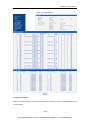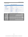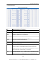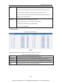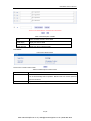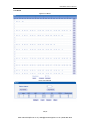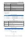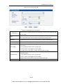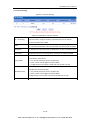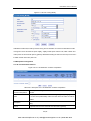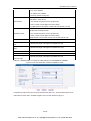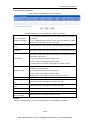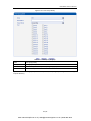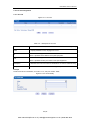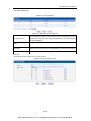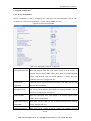
1
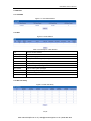
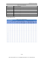
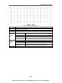
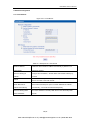
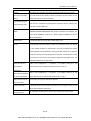
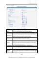
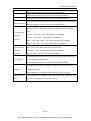
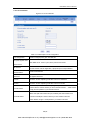
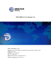
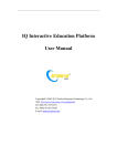
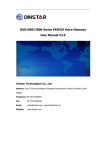
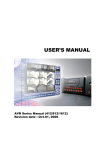
DWG2000D GSM VoIP Gateway User Manual V1.0 Shenzhen Dinstar Technologies Co., Ltd. Address: Floor 6, Guoxing Building, Changxing Road, Nanshan District, Shenzhen, Guangdong P.R.China. 518052 Tel: +86 755 2645 6664 Fax: +86 755 2645 6659 Email: [email protected], [email protected] Website: www.dinstar.com DWG2000D-32G User Manual Revision Records Document version V1.0 Firmware version 2.22.02.01 Revised by Technical Support Team Date 23/05/2012 Changes The first version 1 / 57 www.InternetVoipPhone.co.uk | [email protected] | 0800 088 4846 DWG2000D-32G User Manual Table of Contents 1. Equipment Introduction ............................................................................................................. 4 1.1 Introduction ....................................................................................................................... 4 1.2 Applications Scenario ...................................................................................................... 4 1.3 Product Appearance ........................................................................................................ 5 1.4 Functions and Features .................................................................................................. 6 1.4.1 Protocol Standard Supported.............................................................................. 6 1.4.2 System Function ................................................................................................... 6 1.4.3 Industrial Standards Supported .......................................................................... 6 1.4.4 General Hardware Specification......................................................................... 7 2. Equipment Quickly Installation ................................................................................................. 7 2.1 Installation Notice ............................................................................................................ 7 2.2 Installation Procedure ..................................................................................................... 7 2.2.1 Install SIM Card .................................................................................................... 7 3. Network Configuration............................................................................................................... 8 3.1 Attentions .......................................................................................................................... 8 3.2 General Feature Codes for System Setting ................................................................. 8 3.3 Static IP Configuration..................................................................................................... 9 3.4 DHCP Configuration ........................................................................................................ 9 4. WEB Configuration .................................................................................................................. 10 4.1 Access the System through HTTP .............................................................................. 10 4.2 WEB Configuration ........................................................................................................ 10 4.3 System Information........................................................................................................ 11 4.3.1 System Information ............................................................................................ 12 4.3.2 Mobile Information .............................................................................................. 13 4.3.3 SIP Information ................................................................................................... 14 4.4 Statistics .......................................................................................................................... 15 4.4.1 TCP/UDP ............................................................................................................. 15 4.4.2 RTP ....................................................................................................................... 15 4.4.3 SIP Call History ................................................................................................... 15 4.4.4 IP to GSM Call History ....................................................................................... 16 4.5 Network Configuration .................................................................................................. 18 4.5.1 Local Network ..................................................................................................... 18 4.5.2 VLAN Parameter................................................................................................. 19 4.5.3 ARP ....................................................................................................................... 20 4.6 Mobile Configuration ..................................................................................................... 20 4.6.1 Basic Configuration ............................................................................................ 21 4.6.2 Mobile Configuration .......................................................................................... 22 4.6.3 PIN Management ................................................................................................ 24 4.6.4 SMSC ................................................................................................................... 25 4.6.5 SMS ...................................................................................................................... 25 4.6.6 USSD.................................................................................................................... 26 4.6.7 Carrier .................................................................................................................. 27 2 / 57 www.InternetVoipPhone.co.uk | [email protected] | 0800 088 4846 DWG2000D-32G User Manual 4.6.8 BCCH ........................................................................................................................... 28 4.7 Routing Configuration ................................................................................................... 29 4.7.1 Routing Parameter ............................................................................................. 29 4.7.2 IP->Tel Routing ................................................................................................... 29 4.7.3 Tel->IP Routing ................................................................................................... 31 4.8 Manipulaton Configuration ........................................................................................... 33 4.8.1 IP->Tel Destination Numbers ............................................................................ 33 4.8.2 Tel->IP Source Numbers ................................................................................... 35 4.8.3 Tel->IP Destination Numbers ............................................................................ 36 4.9 Operation ........................................................................................................................ 37 4.9.1 IP->Tel Operation................................................................................................ 38 4.9.2 Tel->IP Operation ................................................................................................ 39 4.10 Port Group Configuration ........................................................................................... 40 4.10.1 Port Group ......................................................................................................... 40 4.11 IP Trunk Configuration ................................................................................................ 42 4.11.1 IP Trunk .............................................................................................................. 42 4.11.2 IP Trunk Group ..................................................................................................... 43 4.12 System Configuration.................................................................................................. 44 4.12.1 Service Configuration ...................................................................................... 44 4.12.2 SIP Configuration ............................................................................................. 46 4.12.3 Port Parameter ................................................................................................. 48 4.13 Digit Map ....................................................................................................................... 49 4.14 Tools .............................................................................................................................. 50 4.14.1 Firmware Upload .............................................................................................. 50 4.14.2 Management Parameter.................................................................................. 50 4.14.3 Config Backup................................................................................................... 51 4.14.4 Data Restore ..................................................................................................... 51 4.14.5 IVR Voice Prompt Upload ............................................................................... 51 4.14.6 PING test ........................................................................................................... 52 4.14.7 Tracert Test ........................................................................................................ 52 4.14.8 Login Password ................................................................................................ 53 4.14.9 Factory Reset .................................................................................................... 54 4.14.10 Restart ............................................................................................................. 54 5. FAQ ............................................................................................................................................ 54 6. Glossary .................................................................................................................................... 56 3 / 57 www.InternetVoipPhone.co.uk | [email protected] | 0800 088 4846 DWG2000D-32G User Manual 1. Equipment Introduction This chapter mainly introduces functions and structures of DWG2000D-32G. 1.1 Introduction DWG2000D-32G is full functions VoIP gateway based on IP and GSM network, which provides a flexible network configuration, powerful features, and good voice quality. It works for carrier grade, enterprise, residential users for cost-effective solution. 1.2 Applications Scenario DWG2000D-32G implements smooth transition between PLMN (GSM) and VoIP network. With the development of users and telecom service, mobile network and fixed network integration will be steadily increasing. DWG2000D-32G provides high quality VoIP service which perfectly meets the requirement. A typical application scenario shown as figure 1-2-1 Figure 1-2-1 application scenario 4 / 57 www.InternetVoipPhone.co.uk | [email protected] | 0800 088 4846 DWG2000D-32G User Manual 1.3 Product Appearance The appearance of DWG2000D-32G shows as follow Figure 1-3-1 Front view of DWG2000D-32G Table 1-3-1 Description of Front view Index Sign Description 1 ANT Interface Standard antenna interface 2 ANT indicator Indicator of SIM card, status: register, unregister 3 LAN 10/100M Base-TX, RJ-45 4 Console Serial port, it is a serial communication physical interface with RS232 5 RST standard Keep press for 7 seconds to restore the factory setting 6 Run Indicate the status of the device. 7 Power Indicate the status of the power connection Figure 1-3-2 Rear view of DWG2000D-32G 5 / 57 www.InternetVoipPhone.co.uk | [email protected] | 0800 088 4846 DWG2000D-32G User Manual 1.4 Functions and Features 1.4.1 Protocol Standard Supported Standard SIP and MGCP(option) protocol; Simple Traversal of UDP over NATs (STUN); Point-to-point protocol over Ethernet (PPPoE); Hypertext Transfer Protocol (HTTP); Dynamic Host Configuration Protocol (DHCP); Domain Name System (DNS); ITU-T G.711α-Law/μ-Law、G.723.1、G.729AB; VLAN and VPN 1.4.2 System Function PLC: Packet loss concealment VAD: Voice activity detection CNG: Comfort Noise Generation Local/Remote SIM card work mode Adjustable gain of port DTMF adjustment Balance alarm Lock/unlock SIM/UIM Mobile number display rejection Sending/receiving SMS Customize IVR Recording White and black list One number access Open API for SMS, support USSD Echo Cancellation (with ITU-T G.168/165 standard) Automatic negotiate network Hotline BCCH 1.4.3 Industrial Standards Supported Stationary use environment: EN 300 019: Class 3.1 Storage environment: EN 300 019: Class 1.2 Transportation environment: EN 300 019: Class 2.3 Acoustic noise: EN 300 753 CE EMC directive 2004/108/EC EN55022: 2006+A1:2007 EN61000-3-2: 2006, EN61000-3-3: 1995+A1: 2001+A2: 2005 EN55024: 1998+A1: 2001+A2: 2003 Certifications: FCC, CE 6 / 57 www.InternetVoipPhone.co.uk | [email protected] | 0800 088 4846 DWG2000D-32G User Manual 1.4.4 General Hardware Specification Power Supply: 220VAC Temperature: 0~40 ℃(Operation), -20~80 ℃(storage) Humidity: 5%~90%RH Power Consumption: 80W Dimensions: 440(W) x330 (D) x66 (H) mm Net weight: 6.4 kg 2. Equipment Quickly Installation This chapter mainly introduces DWG2000D-32G hardware installation and connection of equipment. 2.1 Installation Notice DWG2000D-32G provides standard RJ45 with 10Mbps or 100Mbps interfaces. For Wireless part, make sure antennas connecting well on device. Inserting SIM cards and GSM channels should work properly. 2.2 Installation Procedure 2.2.1 Install SIM Card When installing SIM card, loosen the screws on the front panel of device. Procedure shows as below: Loosen screw, draw out the user board Inset the SIM card to the SIM slot of the back of the user board The user board inserted into the device Tighten the screws Figure 2-2-1 SIM card Installation (1) 7 / 57 www.InternetVoipPhone.co.uk | [email protected] | 0800 088 4846 DWG2000D-32G User Manual Figure 2-2-2 SIM card Installation (2) 3. Network Configuration In this chapter we will introduce the initial configuration of DWG2000D-32G. All of the network parameters of the gateway can be configured by IVR guidance. 3.1 Attentions In each step, if user hears an IVR message of “setting successful”, which means that user has finished this step successfully. However, if user hears a “setting failed” message, please re-do that step again. 3.2 General Feature Codes for System Setting Table 3-3-1 Feature codes for system setting Feature codes Description *114# Play SIP user ID *150*a# Set IP address(static/DHCP), a can be digit 1 or 2,*150*1# is static IP address *152*a*b*c*d# Configure IP address, a, mode b, c, d are the four fields of IP address. mode, *150*2# is DHCP *153*a*b*c*d# Configure subnet mask. a, b, c, d are the four fields of the subnet mask *156*a*b*c*d# Configure the device gateway, a, b, c, d are the four fields of the device gateway *158# Report LAN port IP address *159# Report WAN port IP address Setting the work mode (route or bridge), * 157 * 0 # is route mode, * 157 * 1 # is *157 bridge mode 8 / 57 www.InternetVoipPhone.co.uk | [email protected] | 0800 088 4846 DWG2000D-32G User Manual *195# Play record *198# Clear record *199# Setting Record. dial*199# start record(≤ 20s), then press # end the recording *111# Restart device 3.3 Static IP Configuration This is an optional configuration step. In case of user forgot the IP address or the device can’t obtain IP address from local network properly, IVR guideline may help to fix it. Assume that DWG2000D-32G IP address to be 172.16.80.89, subnet mask is 255.255.0.0, default gateway is 172.16.1.1, configure it through IVR as following steps: 1) Please make sure SIM card installed well and registered 2) Dial the phone number of the SIM card. Press "*150*1#" after heard "dial the extension number ". Hang up after heard “setting successful" prompt. 3) Dial the phone number of the SIM card. Dial "* 152 * 172 * 16 * 80 * 89 #"after heard “dial the extension number ". Hang up after heard “setting successful". 4) Dial the phone number of the SIM card. Dial "*153*255*255*0*0#" after heard "dial the extension number ". Hang up after heard "setting successful" 5) Dial the phone number of the SIM card. Dial "*156*172*16*1*1#" after heard "dial extension number ". Hang up after heard "setting successful" 6) Dial the phone number of the SIM card. Dial "*111#" after heard "dial extension number ", that will restart the device 7) Dial the phone number of the SIM card. Dial "*158#" after heard “dial extension number ". It will play report the IP address of LAN port. 3.4 DHCP Configuration DHCP mode configure as follows: 1) Please make sure hardware installation have finished 2) Dial the phone number of the SIM card. Dial "*150*2#" after heard "dial extension number ". That means the DHCP is configured successfully 3) Restart the device, wait for 30 seconds, and then dial the SIM card telephone number, enter "*158 #" to query the IP address Note: If reporting the IP address is 0.0.0.0, which means that the gateway could not obtain a IP address successfully. Please check: 9 / 57 www.InternetVoipPhone.co.uk | [email protected] | 0800 088 4846 DWG2000D-32G User Manual 1) Make sure the device have been connected to the network 2) Make sure the DHCP Server is working. If there is no DHCP Server, please set the IP of device to static IP 3) Restart the gateway and try again 4. WEB Configuration This charpter describes web configuration of DWG2000D-32G. 4.1 Access the System through HTTP The default IP of LAN port is 192.168.11.1,before web access, make sure the PC is able to ping continuously. Here the device’s IP address is 172.16.80.89, after input this IP, the GUI shows as below: Figure 4-1-1 WEB log interface Enter username and password and then click “OK” in configuration interface. The default username and password are “admin/admin”. We are strongly recommend to change the default password for security purpose. 4.2 WEB Configuration DWG2000D-32G WEB configuration interface consists of the navigation tree and the detail configuration interfaces. 10 / 57 www.InternetVoipPhone.co.uk | [email protected] | 0800 088 4846 DWG2000D-32G User Manual Figure 4-2-1 WEB introduce 4.3 System Information System information interface shows the basic information of status information, Mobile information and SIP information. 11 / 57 www.InternetVoipPhone.co.uk | [email protected] | 0800 088 4846 DWG2000D-32G User Manual 4.3.1 System Information Figure 4-3-1 system information Table 4-3-1 Description of system information MAC Address Displays current MAC of device, for example: 00-00-00-00-00-00 Network Mode DWG2000D-32G works on bridge mode Network Shows IP address and subnet mask DNS Server Displays DNS server IP address in the same network with the gateway System Up Duration shows the time period of the device running. For example,:1h: 20m, 24s Traffic Statistics Calculates the netflow, including the total bytes of message received and sent. Version information shows the current firmware version 12 / 57 www.InternetVoipPhone.co.uk | [email protected] | 0800 088 4846 DWG2000D-32G User Manual 4.3.2 Mobile Information Figure 4-3-2 Mobile information Table 4-3-2 Description of mobile information Port GSM channel number, it is range from 0 to 31 Type Indicates the current type of network. Such as CDMA or GSM IMSI International Mobile Subscriber Identity, it is the uniquely identifies of SIM card Status Indicates the register status of current GSM module Remaining Call Limited call duration of SIM card, when call duration is out of that duration, the call Duration would be disconnected. This option shows remaining talk time. Carrier Displays the network carrier of current SIM card. Signal Quality Displays the signal strength of in each channels of GSM BER Bit error rate, internal parameter ASR Answer Seizure Ratio is a measure of network quality. Its calculated by taking the number of successfully answered calls and dividing by the total number of calls attempted. Since busy signals and other rejections by the called number count as call failures, the ASR value can vary depending on user behavior. ACD The Average Call Duration (ACD) is calculated by taking the sum of billable seconds (billable) of answered calls and dividing it by the number of these answered calls. 13 / 57 www.InternetVoipPhone.co.uk | [email protected] | 0800 088 4846 DWG2000D-32G User Manual PDD Post Dial Delay (PDD) is experienced by the originating customer as the time from the sending of the final dialled digit to the point at which they hear ring tone or other in-band information. Where the originating network is required to play an announcement before completing the call then this definition of PDD excludes the duration of such announcements. Call Status Show the status of call, its include 3 type of status : Idle: the GSM channel is free. It is ready to receive the call Processing: the call is delivering to mobile network Active: the call is established 4.3.3 SIP Information Figure 4-3-3 SIP information Displays registration status information with Softswitch platform or SIP Server Table 4-3-3 Description of SIP information Port The number of SIP channel, DWG2000D-32G has 32 ports SIP User ID SIP registration account which are provided by the Softswitch and SIP server Register Status Shows the registration status of VoIP channel, including registered and unregistered. Status Show the status of port, include "onhhok" and "offhook" 14 / 57 www.InternetVoipPhone.co.uk | [email protected] | 0800 088 4846 DWG2000D-32G User Manual 4.4 Statistics 4.4.1 TCP/UDP Figure 4-4-1 TCP/UDP Statistics 4.4.2 RTP Figure 4-4-2 PRI Statistics Table 4-4-2 Description of RTP Statistics Port The port of RTP statistics Payload Type The voice code of this channel, Include G.723.1/PCMA/PCMU/G.729AB Packet Period Time of packaging Local Port Local port of transmitting RTP packages Peer IP End of equipment IP address Peer Port Peer port of receiving RTP packages Send Packet Total of sending RTP packages Recv Packet Total of receiving RTP packages Loss Packet Total of losing RTP packages Jitter Length of delay jitter Duration Time(s) Both ends of the call time 4.4.3 SIP Call History Figure 4-4-3 SIP Call History 15 / 57 www.InternetVoipPhone.co.uk | [email protected] | 0800 088 4846 DWG2000D-32G User Manual Table of 4.4.3 SIP Call History Port The port of Call statistics Incoming Received The amount of received incoming calls which coming from IP part Incoming connected The amount of incoming calls which have connected Incoming Answered The amount of incoming calls which answered by IP part Incoming Failed The amount of incoming calls which failed Outgoing Attempted The amount of outgoing calls which attempted to IP part Outgoing Connected The amount of outgoing calls which have connected Outgoing Answered The amount of outgoing calls which answered by IP part Outgoing Failed The amount of outgoing calls which failed 4.4.4 IP to GSM Call History Figure 4-4-4 IP to GSM Call History 16 / 57 www.InternetVoipPhone.co.uk | [email protected] | 0800 088 4846 DWG2000D-32G User Manual Table of 4.4.4 IP to GSM Call History Port The port of Call statistics Call The number of IP->GSM call Duration Call duration Answered Response statistics Call Failed Canceled The number of cancellation caused by SIP Caused by Timeout The number of timeout caused by SIP SIP Not Allowed The number of banned call caused by SIP Negotiation failed By SIP signaling negotiation fails cause calls for failure Call Failed Busy The number of call failed caused by busy Caused by No Answer The number of call failed caused by no answer GSM No Dialtone The number of call failed caused by no dialtone No Carrier The number of call failed caused by no find carrier Other The number of call failed by other 17 / 57 www.InternetVoipPhone.co.uk | [email protected] | 0800 088 4846 DWG2000D-32G User Manual 4.5Network Configuration 4.5.1 Local Network Figure 4-5-1 Local Network Table 4-5-1 Description of Local network Obtain IP Address Automatically Enable the device obtain IP Address automatically by DHCP or not. Default is enabling Use the Following IP Configure the "IP Address", "Subnet Mask" and "Default Gateway" by Address manual Both of account and password are provided by ISP. Use this mode when PPPoE there is not router in the local network. Obtain DNS Server When enable the WAN port option of "Obtain DNS Server Address Address Automatically Automatically" , which will be enabled subsequently. Use the Following DNS Fill in the IP address of "Primary DNS Server" and "Secondary DNS Server Addresses Server" 18 / 57 www.InternetVoipPhone.co.uk | [email protected] | 0800 088 4846 DWG2000D-32G User Manual 4.5.2 VLAN Parameter Figure 4-5-2 VLAN Parameter Table 4-5-2 Description of VLAN Parameter Data VLAN Data 802.1Q VLAN ID Under standard VLAN protocol set VLAN ID. “0” is used to management VLAN, and can’t be used to service configure. Data 802.1p Priority (0-7) Under 802.1q protocol users can set VLAN priority Voice 802.1Q VLAN ID Under standard VLAN protocol set VLAN ID Voice 802.1p Priority (0-7) Under 802.1q protocol users can set VLAN priority IP address Users can set DHCP or static IP address Voice VLAN DNS Server Users can set DHCP or static DNS server IP address Management Management 802.1Q VLAN Under standard VLAN protocol set VLAN ID. “0” is VLAN ID used to management VLAN, and can’t be used to Voice VLAN service configure. Management 802.1p Priority Under 802.1p protocol users can set VLAN priority (0-7) IP address Users can set DHCP or static IP address Management VLAN DNS Users can set DHCP or static DNS server IP address Server 19 / 57 www.InternetVoipPhone.co.uk | [email protected] | 0800 088 4846 DWG2000D-32G User Manual 4.5.3 ARP The ARP function mainly used to query and add the map of IP and MAC. There are static or dynamic ARP entries. Like other routers, the gateway can automatically find the network device on the same segment. But, sometimes you don't want to use this automatic mapping; you'd rather have fixed (static) associations between an IP address and a MAC address. Gateway provides you the ability to add static ARP entries to: Protect your network against ARP spoofing Prevent network confusion as a result of misconfigured network device Figure 4-5-4 Add ARP 4.6 Mobile Configuration This is Mobile Configuration menu. Figure 4-6-1Basic Configuration 20 / 57 www.InternetVoipPhone.co.uk | [email protected] | 0800 088 4846 DWG2000D-32G User Manual 4.6.1 Basic Configuration Figure 4-6-2Basic Configuration Table 4-6-1 Description of Basic Configuration Dial Tone Gain It is the dial tone volume of call waiting, dial tone of mobile module when call out. default value is 8 dB. Select Band Acording to carrier’s band standards. Standards are as belows: GSM: 850/900/1800/1900 MHz; CDMA: 800 MHz Remote API Enable API is mainly for third party software which developed based-on Dinstar API protocol. Its help to provide bulk SMS/ SMS/USSD over IP service. API Server Address It is the remote IP address who uses API. This is an option when selecting "Yes" under 'remote API enable" API Server Port It is the port number of IP transmission. This is an option when selecting "Yes" under "remote API enable". The port cannot conflict with the other application software. The default value is 12000 Auto Reset Module Reset modular by automatically while some special errors happened, such as No Carrier, No Dial tone Counts of No A kind of the error, continuously N times will reboot the modular. CARRIER to reset N is range from 3 to 255. Counts of No DIAL A kind of the error, continuously N times will reboot the modular. TONE to reset N is range from 3 to 255. 21 / 57 www.InternetVoipPhone.co.uk | [email protected] | 0800 088 4846 DWG2000D-32G User Manual 4.6.2Mobile Configuration Figure 4-6-2 Mobile State 22 / 57 www.InternetVoipPhone.co.uk | [email protected] | 0800 088 4846 DWG2000D-32G User Manual Figure 4-6-3 Mobile Configuration Table 4-6-2 Description of Mobile Configuration Mobile Number Phone number of current SIM card Enable Call Duration Definite maximum call duration for single call. Example: if Time of single Limitation of single call call set to 10, the call will be disconnected after talking 10*step seconds Step Step length value range is 1-120 s, step length multiplied by time of single call just said a single call duration time allowed. Time of single call The value of limitation single call, this value range is 1-65535. step length multiplied by time of single call just said a single call duration time allowed. Enable Call Duration This function is to limit the total call duration of GSM channel. The max call Limitation duration is between 1 to 65535 minutes. Auto Reset Automatic restore remaining talk time, that is, get total call minutes of GSM channel Reset Period Reset call minutes by date, by week, by month Next Reset time Defined next reset date, system will count start from that date and work as Reset Period setting Minimum Charging Time A single call over this time, GSM side of the operators began to collect fees, unit for seconds. Alarm Threshold(via SMS) Define a threshold value of call minutes, while the call minutes less than this value, the gateway will send alarm information to designated phone 23 / 57 www.InternetVoipPhone.co.uk | [email protected] | 0800 088 4846 DWG2000D-32G User Manual number via SMS. Mobile Number (Receiving Receiving alarm phone number, user will received alarm message from Alarm) gateway. Port Description for Alarm Alarm port information description, which will be sent to user mobile phone with alarm information. SIM Remain Time This value is multiplied by to step length is a rest call time Restore Time Restore the rest of the SIM card talk time to the maximum call duration CLIR Caller ID restriction, this function is used to hidden caller ID of SIM card number. The gateway will add “#31#” in front of mobile number. This function must support by Operator. Mobile Tx Gain Control IP to GSM side of call the gain. Default is +6 dB. Mobile Rx Gain Control GSM to IP side of call the gain. Default is +6 dB. 4.6.3 PIN Management Figure 4-6-4 PIN Management Detailed description as below: Table 4-6-4 Description of PIN Management Select Port Selects the GSM channel No. SIM Card Lock Whether to allow lock the SIM card PIN Code Personal identification number of SIM card. In the status of SIM card locked, PIN can be modified to prevent SIM card from being stolen. 24 / 57 www.InternetVoipPhone.co.uk | [email protected] | 0800 088 4846 DWG2000D-32G User Manual 4.6.4 SMSC Figure 4-6-5 SMSC SMS center of mobile, in most places, the celluar modular will automatically detect the SMSC number. This configurable option is used in a situation that the SMSC number could not detected by celluar modular. When such case happens, please contact with mobile service provider to identify the SMSC number and then add SMSC number in SMSC configurable web interface. 4.6.5 SMS Figure 4-6-6 SMS Message Table 4-6-5 Description of SMS sending Select Port Users can select a defined channel or random channel to send SMS. Input the recevier’s mobile phone number to send SMS. Encoding Two kinds of message encoding under PDU models, 7-bit code used to sent ordinary ASCII characters; UCS2 coding used to sent Unicode characters. To Mobile phone No. of the receiver Message Content of the SMS. The length is limited to 300 characters. 25 / 57 www.InternetVoipPhone.co.uk | [email protected] | 0800 088 4846 DWG2000D-32G User Manual 4.6.6 USSD USSD (Unstructured Supplementary Service Data) is a Global System for Mobile(GSM) communication technology that is used to send text between a mobile phone and an application program in the network. Applications may include prepaid roaming or mobile chatting. USSD can cluster and group of charge Figure 4-6-7 USSD 26 / 57 www.InternetVoipPhone.co.uk | [email protected] | 0800 088 4846 DWG2000D-32G User Manual Table 4-6-6 Description of USSD Port Select the GSM channel to send USSD USSD Reply Display the state of USSD USSD Request Display the result of sending USSD 4.6.7 Carrier Figure 4-6-8 Select Carrier This function is used to select carrier. Table 4-6-6 Description of select Carrier Select Port Select GSM channel,default Port 0 Select Mode There are two modes to select carrier automatic and manual. Automatic mode can be automatically search operators. Manual mode can choose operators from the carrier list. Carrier List If you select manual mode, you can select carrier from carrier list. 27 / 57 www.InternetVoipPhone.co.uk | [email protected] | 0800 088 4846 DWG2000D-32G User Manual 4.6.8 BCCH Figure 4-6-9 BCCH Figure 4-6-10 BCCH 28 / 57 www.InternetVoipPhone.co.uk | [email protected] | 0800 088 4846 DWG2000D-32G User Manual Table 4-6-7 Description of BCCH Refresh Interval Set frequency detection refresh time Auto Refresh/Stop Refresh Choose whether to refresh frequency Index Serial number MCC Mobile country code, China is 460 MNC Mobile network code, used to distinguish between different network operators LAC Location area codes CID Village identification number BCCH Public radio channel Receive Level Receiving signal strong strength Choose a frequency to lock the operations. 4.7 Routing Configuration 4.7.1 Routing Parameter Figure 4-7-1 Routing Parameter Table 4-7-1Description of Routing Parameter Tel->IP Parameter Globle parameters, it will take effect while number manipulation configured Route calls after The parameters indicate that the gateway will select Tel->IP routes after number manipulation manipulation completed Route calls before The parameters indicate that the gateway will select Tel->IP routes before manipulation number manipulation completed 4.7.2 IP->Tel Routing Figure 4-7-2 IP to Tel Routing 29 / 57 www.InternetVoipPhone.co.uk | [email protected] | 0800 088 4846 DWG2000D-32G User Manual Figure 4-7-3 IP to Tel Routing Add Table 4-7-2 Description of IP to Tel Routing IP ->Tel Routing This item uses to configure outgoing call routes which can be used for recieve the calls from the GSM It uniquely identifies a route. Its value is assigned globally, ranging from 0 to 31. Index The route preferentially match the rules which the value of index is smaller Description It describes the route for the ease of identification. Its value is character string Source IP It specifies the IP of the caller All the caller number must match the source prefix. It specifies the source prefix allow to send call out Source Prefix Any: include anonymous, 0xxxx, 1[2-9]xxxx etc. 0xxxx: consist of some digits such as 015,08,09 1[3-8]6:consist of some prefix, include 136,146,156,166,176, 186 All the called number must match the destination prefix, the call prefix indicates the connected number Destination Prefix Any: include anonymous, 0xxxx, 1[2-9]xxxx etc. 0xxxx: consist of some digits such as 015,08,09 1[3-8]6:consist of some prefix, include 136,146,156,166,176, 186 Destination Its specifies destination Port or Port Group 30 / 57 www.InternetVoipPhone.co.uk | [email protected] | 0800 088 4846 DWG2000D-32G User Manual 4.7.3 Tel->IP Routing Figure 4-7-3 Tel to IP Routing Table 4-7-3 Description of Tel to IP Routing Tel -> IP Routing This item uses to configure incoming call routes which can be used for recieve the calls from the GSM. It uniquely identifies a route. Its value is assigned globally, ranging from 0 to Index 31.The route preferentially match the rules which the value of index is smaller Description It describes the route for the ease of identification. Its value is character string Source Port It specifies the Port or Port Group which will receive the calls from PLMN All the caller number must match the source prefix. It specifies the source prefix allow to send call out Source Prefix Any: include anonymous, 0xxxx, 1[2-9]xxxx etc. 0xxxx: consist of some digits such as 015,08,09 1[3-8]6:consist of some prefix, include 136,146,156,166,176, 186 All the called number must match the destination prefix, the call prefix indicates the connected number Destination Prefix Any: include anonymous, 0xxxx, 1[2-9]xxxx etc. 0xxxx: consist of some digits such as 015,08,09 1[3-8]6:consist of some prefix, include 136,146,156,166,176, 186 Destination Its specifies destination Port or Port Group 31 / 57 www.InternetVoipPhone.co.uk | [email protected] | 0800 088 4846 DWG2000D-32G User Manual Figure 4-7-4 Tel to IP routing Modify It's a default route configured in gateway. It allows any number from source port 0 send call to SIP server with any prefix. Figure 4-7-5 Tel to IP routing Modify Add a GSM to VoIP route. It indicates that the calls coming from Port Group 31<Unicom> will match the prefix ”x.”, ”x.” is a wildcard string which will match any prefix except ”anonymous” calls. Meanwhile sending the calls destination IP 13<eia> if called number match with destination prefix ”00”. 32 / 57 www.InternetVoipPhone.co.uk | [email protected] | 0800 088 4846 DWG2000D-32G User Manual Figure 4-7-6 Tel to IP routing Modify Add GSM to GSM route,its mainly used for saving the cost between two carriers.It indecates that calls coming from Port 0 will match the prefix 13[58], ”13[58]” include prefix 135 and 138, caller number can’t match prefix 135 and 138 will reject by gateway. Meanwhile sending the calls to Port Group 31<Unicom> if called number match with prefix 133. 4.8 Manipulaton Configuration 4.8.1 IP->Tel Destination Numbers Figure 4-8-1 IP->Tel destination numbers manipulation Table 4-8-1 Description of IP->Tel destination numbers manipulation IP->Tel destination numbers manipulation It is an optional configuration item, and is used to add a rule for changing number It uniquely identifies a route. Its value is assigned globally, ranging from 0 Index to 31.The route preferentially match the rules which the value of index is smaller Description Source It describes the rule for the ease of identification. Its value is character string It specifies the source IP which will send the calls to gateway 33 / 57 www.InternetVoipPhone.co.uk | [email protected] | 0800 088 4846 DWG2000D-32G User Manual Any: any IP address IP: specific an IP address IP Group: specific an IP group All the caller number must match the source prefix. It specifies the source prefix allow to send call out Any: include anonymous, 0xxxx, 1[2-9]xxxx etc. Source Prefix 0xxxx: consist of some digits such as 015,08,09 1[3-8]6:consist of some prefix, include 136,146,156,166,176, 186 All the called number must match the destination prefix, the call prefix indicates the connected number Any: include anonymous, 0xxxx, 1[2-9]xxxx etc. Destination Prefix 0xxxx: consist of some digits such as 015,08,09 1[3-8]6:consist of some prefix, include 136,146,156,166,176, 186 Destination Stripped Its specifies destination Port or Port Group Digits from Digits from Left Stripped Right It specifies the length of the digits to be deleted from left It specifies the length of the digits to be deleted from right Prefix to Add Add the new digits in front of the original number Suffix to Add Add the new digits at the end of the original number Number of Digits to leave from right It specifies the length of the digits to be deleted from left Add an IP->Tel Manipulation, to change the called number from 2547888888 to 07888888 Figure 4-8-2 IP->Tel destination numbers manipulation modify It indicates that calls coming from IP Group will match the prefix ”any”, and the called nubmer which match with the prefix ”2547” will delete 3 digits in front of it and replace it by digit ”0”. 34 / 57 www.InternetVoipPhone.co.uk | [email protected] | 0800 088 4846 DWG2000D-32G User Manual 4.8.2 Tel->IP Source Numbers Figure 4-8-3 Tel->IP destination numbers manipulation Table 4-8-2 Description of Tel->IP destination numbers manipulation It is an optional configuration item, and is used to add IP->Tel number Tel->IP destination numbers manipulation change data. The IP->Tel Manipulation defined the rules of add, and deletion of called numbers, which are referenced by IP->Tel routing. It uniquely identifies a route. Its value is assigned globally, ranging from 0 to Index 31. Description It describes the rule for the ease of identification. Its value is character string All the caller number must match the source prefix. It specifies the source prefix allow to send call out Any: include anonymous, 0xxxx, 1[2-9]xxxx etc. Source Prefix 0xxxx: consist of some digits such as 015,08,09 1[3-8]6:consist of some prefix, include 136,146,156,166,176, 186 All the called number must match the destination prefix, the call prefix indicates the connected number Any: include anonymous, 0xxxx, 1[2-9]xxxx etc. Destination Prefix 0xxxx: consist of some digits such as 015,08,09 1[3-8]6:consist of some prefix, include 136,146,156,166,176, 186 Destination Stripped Its specifies destination Port or Port Group Digits from Digits from Left Stripped Right It specifies the length of the digits to be deleted from left It specifies the length of the digits to be deleted from right Prefix to Add Add the new digits in front of the original number Suffix to Add Add the new digits at the end of the original number Number of Digits to Leave from Right It specifies the number of Digits to leave from Right Example: Add an IP->Tel Manipulation, to change the called number from 2547888888 to 07888888 35 / 57 www.InternetVoipPhone.co.uk | [email protected] | 0800 088 4846 DWG2000D-32G User Manual Figure 4-8-4 Tel ->IP destination numbers manipulation add It indicates that calls coming from IP Group will match the prefix ”any”, and the called nubmer which match with the prefix ”2547” will delete 3 digits in front of it and replace it by digit ”0”. 4.8.3 Tel->IP Destination Numbers Figure 4-8-5 Tel->IP destination numbers manipulation Table 4-8-3 Description of Tel->IP destination numbers manipulation It is an optional configuration item, and is used to add IP->Tel number change Tel->IP destination numbers manipulation data. The IP->Tel Manipulation defined the rules of add, and deletion of called numbers, which are referenced by IP->Tel routing. It uniquely identifies a route. Its value is assigned globally, ranging from 0 to Index 31. Description It describes the route for the ease of identification. Its value is character string All the caller number must match the source prefix. It specifies the source prefix allow to send call out Source Prefix Any: include anonymous, 0xxxx, 1[2-9]xxxx etc. 0xxxx: consist of some digits such as 015,08,09 1[3-8]6:consist of some prefix, include 136,146,156,166,176, 186 Destination Prefix All the called number must match the destination prefix, the call prefix indicates the connected number 36 / 57 www.InternetVoipPhone.co.uk | [email protected] | 0800 088 4846 DWG2000D-32G User Manual Any: include anonymous, 0xxxx, 1[2-9]xxxx etc. 0xxxx: consist of some digits such as 015,08,09 1[3-8]6:consist of some prefix, include 136,146,156,166,176, 186 Destination Stripped Its specifies destination Port or Port Group Digits from Digits from Left Stripped Right It specifies the length of the digits to be deleted from left It specifies the length of the digits to be deleted from right Prefix to Add Add the new digits in front of the original number Suffix to Add Add the new digits at the end of the original number Number of Digits to Leave from Right It specifies the number of Digits to leave from Right Example: Add an IP->Tel Manipulation, to change the called number from 2547888888 to 07888888 Figure 4-8-6 Tel->IP destination numbers manipulation It indicates that calls coming from IP Group will match the prefix ”any”, and the called nubmer which match with the prefix ”2547” will delete 3 digits in front of it and replace it by digit ”0”. 4.9 Operation When configure hotline, must configure operation. 37 / 57 www.InternetVoipPhone.co.uk | [email protected] | 0800 088 4846 DWG2000D-32G User Manual 4.9.1 IP->Tel Operation Figure 4-9-1 IP->Tel Operation Table 4-9-1 Description of IP->Tel Operation It is an optional configuration item. Operation configuration essentially IP->Tel Operation involves allow, barring some IP and IP Group send calls to certain numbers. It includes: forbid call, call allowance, auto call, and password authentication. It uniquely identifies a route. Its value is assigned globally, ranging from 0 to Index 31. It specifies the source IP which will send the calls to gateway Source IP Any: any IP address IP: specific an IP address IP Group: specific an IP group All the caller number must match the source prefix. It specifies the source prefix allow to send call out Source Prefix Any: include anonymous, 0xxxx, 1[2-9]xxxx etc. 0xxxx: consist of some digits such as 015,08,09 1[3-8]6:consist of some prefix, include 136,146,156,166,176, 186 All the called number must match the destination prefix, the call prefix indicates the connected number Destination Prefix Any: include anonymous, 0xxxx, 1[2-9]xxxx etc. 0xxxx: consist of some digits such as 015,08,09 1[3-8]6:consist of some prefix, include 136,146,156,166,176, 186 Its specifies number analysis rule Forbid call Operation Allow call Auto call Password authenticate Description It describes the route for the ease of identification. Its value is character string Example: Index 31: barring the certain calling number from IP 14<elastix> 38 / 57 www.InternetVoipPhone.co.uk | [email protected] | 0800 088 4846 DWG2000D-32G User Manual Figure 4-9-2 IP->Tel Operation Modify It indicates that calling party from IP 14<elastix> matched prefix 2877, and also called party matched prefix 07 are not allowed call out. The calls match this rule will be rejected by gateway. Index 29: definite a rule for IP 17<FreeSentral> that all the calls must go with valid password authentication. Figure 4-9-3 IP->Tel Operation Modify 4.9.2 Tel->IP Operation Figure 4-9-4 Tel->IP Operation 39 / 57 www.InternetVoipPhone.co.uk | [email protected] | 0800 088 4846 DWG2000D-32G User Manual Table 4-9-2 Description of Tel->IP Operation It is an optional configuration item. Operation configuration essentially Tel->IP Operation involves allow, barring some IP and IP Group send calls to certain numbers. It includes: forbid call, call allowance, auto call, and password authentication. It uniquely identifies a rule. Its value is assigned globally, ranging from 0 to Index 31. It specifies the source IP which will send the calls to gateway Source IP Any: any IP address IP: specific an IP address IP Group: specific an IP group All the caller number must match the source prefix. It specifies the source prefix allow to send call out Source Prefix Any: include anonymous, 0xxxx, 1[2-9]xxxx etc. 0xxxx: consist of some digits such as 015,08,09 1[3-8]6:consist of some prefix, include 136,146,156,166,176, 186 All the called number must match the destination prefix, the call prefix indicates the connected number Destination Prefix Any: include anonymous, 0xxxx, 1[2-9]xxxx etc. 0xxxx: consist of some digits such as 015,08,09 1[3-8]6:consist of some prefix, include 136,146,156,166,176, 186 Its specifies number analysis rule Forbid call Operation Allow call Auto call Password authenticate Description It describes the route for the ease of identification. Its value is character string 4.10 Port Group Configuration 4.10.1 Port Group Figure 4-10-1 Port Group 40 / 57 www.InternetVoipPhone.co.uk | [email protected] | 0800 088 4846 DWG2000D-32G User Manual Figure 4-10-2 Port Group Modify Table 4-10-1 Description port group Index Port group priority Description Port group decription Select Mode Choose the port that composition port group by drop-down list select mode Port The selected port If you have the need for a group of port the same operation, then port group of configuration can help you improve efficiency. 41 / 57 www.InternetVoipPhone.co.uk | [email protected] | 0800 088 4846 DWG2000D-32G User Manual 4.11 IP Trunk Configuration 4.11.1 IP Trunk Figure 4-11-1 IP Trunk Table 4-11-1 Description of IP Trunk IP Trunk Add remote IP of softswitch, SIP server which will send call traffics to gateway. Index It uniquely identifies a trunk, ranging from 0 to 31. It is an interworking parameter between the remote Softswitch and the SIP IP server. It specifies the IP address of the peer equipment. It is an interworking parameter between the remote Softswitch and the SIP Port server. It specifies the SIP port number of the peer equipment Description It describes the trunk for the ease of identification. Its value is character string KeepAlive Enable It is use to detect connection between GSM gateway and remote IP trunk Example To add a remote IP of Softswitch, set “index” to “31”, SIP port number “5060” Figure 4-11-2 IP Trunk Modify 42 / 57 www.InternetVoipPhone.co.uk | [email protected] | 0800 088 4846 DWG2000D-32G User Manual 4.11.2 IP Trunk Group Figure 4-11-3 IP Trunk Group Table 4-11-2 Description of IP Trunk Group This configuration is optional, and is used to add the IP that have the same IP Trunk Group attributes to an IP group. The IP group will referenced by IP->Tel routing and number manipulation. It uniquely identifies a route. Its value is assigned globally, ranging from 0 to Index 31. Description It describes the route for the ease of identification. Its value is character string IP It specifies the IP will add to IP group Example To add an IP group, set index 10,14,17 to IP group 18 Figure 4-11-4 IP Trunk group modify 43 / 57 www.InternetVoipPhone.co.uk | [email protected] | 0800 088 4846 DWG2000D-32G User Manual 4.12 System Configuration 4.12.1 Service Configuration Service Configuration is used for configuring voice calls and some small businesses, such as Call Progress Tone, codec, silence suppression, * service, the second dial and so on Figure 4-12-1 Service Configuration Table 4-12-1 Description of Service Configuration LOCAL Start RTP PORT Means the initial port when RTP voice stream transmit in the IP network , in general, using the factory default values. When there are multiple DINSTAR series voice products, and the network gateway or router’s NAT with loopholes, user can try changing this item Enable Silence Enable the "silence suppression" almost no impact on call quality, and can save Suppression about half of the bandwidth. Call Progress Tone Each country has its different call progress tone required standards, such as busy tone, ring back tones and ring tone. Preferred Coders Means the code format when Voice transfer on IP network, support PCMA, PCMU, G.723.1 andG.729AB. Enable PSTN Incoming Means when call from PSTN side, you can dial the function keys for checking Configuration number, setting IP and so on Enable Auto Outgoing Means when call out , whether by ordinal or polling pick to Select a Channel, 44 / 57 www.InternetVoipPhone.co.uk | [email protected] | 0800 088 4846 DWG2000D-32G User Manual Routing IP to PSTN One Stage this feature are generally used when use the same SIP User ID to register The User ID will be sent directly to PSTN, for example: the user calls 6715, the device will sent 6715 User ID to PSTN Dialing Play Voice Prompt for PSTN Incoming Calls Setting is yes, when through the PSTN calls to the Channel, the device will with the clew tone, the default is "Please dial the extension User ID"; setting to No, the device will play dial tone DTMF DWG2001/DWG2004/DWG2000D-32G support RFC2833 and SIGNAL two ways. DTMF INTERVAL range is 50 ~ 800ms, DTMF VOLUME can use the default Configuration Nat Traversal Include Static NAT and STUN, NAT’s UDP simple cross STUN STUN (Simple Traversal of UDP over NATs ) is a network protocol. It is allowed to stay behind the NAT (or multiple NAT) client part to identify their clients’ public address, found himself after what Type of NAT and NAT for a particular Channel is bound to a local Internet terminal Channel. This information is used for two host to set up UDP communication behind the same NAT router. The agreement defined by the RFC 3489 Allow call from IP to Refer to "SIP Configuration" -> "Is register" . If "Is register" setting is no, this PSTN without option need set Yes ,to avoid that the devices can not call out Registration Allow Call from PSTN to Refer to "SIP Configuration" -> "Is register" . If "Is register" setting is no, this IP without Registration option need set Yes ,to avoid that the devices can not call in Reject Anonymous call The incoming anonymous calls will be rejected from IP to PSTN Use # as End Key In General, SIP phones are based on # as the end, if this option is set to No, the dial-up will end expires dial-up time Interdigit Timeout Bit of between the dialing time ,over the time will be seem as end of dial 45 / 57 www.InternetVoipPhone.co.uk | [email protected] | 0800 088 4846 DWG2000D-32G User Manual 4.12.2 SIP Configuration Figure 4-12-2 SIP Configuration Table 4-12-2 SIP Configuration SIP Server Used for configure SIP server address and port, the address can be IP Address, Address also can be a domain nameWhich can be resolved by DNS server SIP Proxy Port Port default setting is 5060. For details, please consult the service provider Outbound proxy, it mainly used in firewall / NAT environment. That make the Outbound Proxy signaling and media streams are able to penetrate the firewall Set the local monitor SIP port ( fixed or random ) , random is every time you start Use Random Port the device will random Select a free SIP port For listening Default set yes, if you want the device can make a call without register, set No, Also Is Register enable the "Allow Call from IP to PSTN without Registration" and "Allow Call from PSTN to IP without Registration" function Register Interval Means how often the equipment will register to the SIP server/proxy The DNS query type defines the type of information that will be requested from DNS DNS query type server DNS refresh The interval of DNS refresh, Range from 0 to 60000 mins, 0 means disable default interval value is disable. 46 / 57 www.InternetVoipPhone.co.uk | [email protected] | 0800 088 4846 DWG2000D-32G User Manual T1 Used to define the SIP protocol T1 timer value, default is 500ms T2 Used to defines the SIP protocol timer values, default value is 4000ms T3 Used to define the T2 timer value in SIP protocol, the default is 5000ms Used to keep communicate between equipment and the SIP server that make the Keep alive Interval device is available . In general, using the factory default values Used to config "From" Mode when Caller ID Is Available when call from GSM to VoIP From Mode when Tel/User: From: caller number <sip:3001@IP>;tag=51088abb Caller ID Is User/User: From: 3001 <sip:3001@IP>;tag=51088abb Available Tel/Tel: From: caller number <sip: caller number @IP>;tag=51088abb User/Tel: From: 3001 <sip: caller number @IP>;tag=51088abb From Mode when Used to config "From" Mode when Caller ID Is Unavailable Caller ID Is Anonymous : From: <sip: Anonymous @IP>;tag=51088abb Unavailable Username : From: <sip: Username @IP>;tag=51088abb Answered: Gateway answer the IP incoming call ( send SIP message "200 OK" to Answer Mode IP part ) after GSM part answered Alerted: Gateway answer the IP incoming call after GSM part Alerted Immediately: Gateway send "183 RING" immediately to IP part while it receive 183 Mode “INVITE" from IP part. Alerted: Gateway send "183 RING" after receive "ring back" from PSTN Response Code switch Used to configure the compatibility of SIP Response Code , Fill the response code in the front , and Fill the switch code in the behind 47 / 57 www.InternetVoipPhone.co.uk | [email protected] | 0800 088 4846 DWG2000D-32G User Manual 4.12.3 Port Parameter Figure 4-12-3 Port Parameter Table 4-12-3 Description of Port Configuration Port Configuration Used to configure ports’ gain, Auto-Dial, etc. ALL ports register used The default is not. If set to "yes" ,all the port will use user ID same user ID SIP User ID Authenticate ID It is the account used for registration, equipment port's unique identifier Used for authenticate Password Its register Password Tx Gain Its DSP’s Tx Gain. Adjusting it will effect volume on GSM side. Rx Gain To VoIP Hotline Its DSP’s Tx Gain. Adjusting it will effect volume on IP side. When PSTN part client calls to this port, gateway will auto forward to the hotline User ID. Leave it blank if you don’t need this function. *Note: Please config Tel->IP Operation if you need this function. When VoIP part client calls to this port, Gateway will auto forward to the To PSTN Hotline number to PSTN part. Leave it blank if you don’t need this function. *Note: Please config IP->Tel Operation if you need this function. 48 / 57 www.InternetVoipPhone.co.uk | [email protected] | 0800 088 4846 DWG2000D-32G User Manual 4.13 Digit Map Figure 4-13-1 Digit map Digit Map Syntax: 1. Supported objects Digit: A digit from "0" to "9". Timer: The symbol "T" matching a timer expiry. DTMF: A digit, a timer, or one of the symbols "A", "B", "C", "D", "#", or "*". 2. Range [] One or more DTMF symbols enclosed between square brackets ("[" and "]"), but only one can be selected. 3. Range () One or more expressions enclosed between round brackets ("(" and ")"), but only one can be selected. 4. Separator |: Separated expressions or DTMF symbols. 5. Subrange -: Two digits separated by hyphen ("-") which matches any digit between and including the two. The subrange construct can only be used inside a range construct, i.e., between "[" and "]". 6. Wildcard x: matches any digit ("0" to "9"). 7. Modifiers .: Match 0 or more times. 8. Modifiers +: Match 1 or more times. 9. Modifiers ?: Match 0 or 1 times. Example: Assume we have the following digit maps: 1. xxxxxxx | x11 and a current dial string of "41". Given the input "1" the current dial 49 / 57 www.InternetVoipPhone.co.uk | [email protected] | 0800 088 4846 DWG2000D-32G User Manual string becomes "411". We have a partial match with "xxxxxxx", but a complete match with "x11", and hence we send "411" to the Call Agent. 2. [2-8] xxxxxx | 13xxxxxxxxx Means that first is "2","3","4","5","6","7" or "8", followed by 6 digits; or first is 13, followed by 9 digits. 3. (13 | 15 | 18)xxxxxxxxx Means that first is "13","15" or "18", followed by 8 digits. 4. [1-357-9]xx Means that first is "1","2","3" or "5" or "7","8","9", followed by 2 digits. 4.14 Tools 4.14.1 Firmware Upload Figure 4-14-1 Firmware upload Select the software, Web or DSP firmware program under correct directory services, and then click upload will complete upgrade the firmware. During the upgrade process, please do not swtich off the power supply, equipment may paralyze. 4.14.2 Management Parameter Figure 4-14-2 Management Parameter 50 / 57 www.InternetVoipPhone.co.uk | [email protected] | 0800 088 4846 DWG2000D-32G User Manual Table 4-14-1 Management Parameter Voice Prompt Language Select the language of voice prompt. There are two kind of voice : English and Chinese Syslog Paremeter Syslog is a standard for network device data logging. It allows separation of the software that generates messages from the system that stores them and the software that reports and analyzes them. It also provides devices which would otherwise be unable to communicate a means to notify administrators of problems or performance. There are 5 grades of syslog, Including NONE, DEBUG, NOTICE, WARNING and ERROR. NTP Parameter The Network Time Protocol (NTP) is a protocol and software implementation for synchronizing the clocks of computer systems over packet-switched, variable-latency data networks. User need to fill the NTP Server Address and select Time Zone 4.14.3 Config Backup Figure 4-14-3 Config backup Click 'Backup' for download configuration file to your computer. 4.14.4 Data Restore Figure 4-14-4 Data restore Send data file from your computer to the device 4.14.5 IVR Voice Prompt Upload By default, when PSTN call incoming, the system will play the default IVR, and also the user can load custom IVR. 51 / 57 www.InternetVoipPhone.co.uk | [email protected] | 0800 088 4846 DWG2000D-32G User Manual Figure 4-14-5 IVR Voice Prompt Upload NOTE: the customize voice files can be recorded using Windows recording programs, the sound format is 8000Hz, 16 bit sampling in mono, with WAV format, size of files can not exceed 190KB. 4.14.6 PING test Ping is utility used to test the reachability of a host on an Internet Protocol (IP) network and to measure the round-trip time for messages sent from the originating host to a destination host. Figure 4-14-6 Ping Test 4.14.7 Tracert Test Trace route is a computer network diagnostic tool for displaying the route (path) and measuring transit delays of packets across an Internet Protocol (IP) network. 52 / 57 www.InternetVoipPhone.co.uk | [email protected] | 0800 088 4846 DWG2000D-32G User Manual Figure 4-14-7 Tracert Test 4.14.8 Login Password Figure 4-14-8 IVR Voice Prompt Upload When using web or telnet Configuration, please enter default user name and password. User can modify the login name and password. 53 / 57 www.InternetVoipPhone.co.uk | [email protected] | 0800 088 4846 DWG2000D-32G User Manual 4.14.9 Factory Reset Figure 4-14-9 Factory Reset Be careful do this operation, after restore factory setting, all the parameters will be changed to the factory default. 4.14.10 Restart Figure 4-14-10 Restart 5. FAQ 5.1 Device has been connected to network physically, but cannot access the gateway 1) Make sure the network cable is ok , can through view the device network port indicator light to determine the physical connection is working or not; 2) Make sure the connected network devices (router, switch or hub) support 10M/100M adaptive, if not, connect the Equipment directly to PC, landing WEB and in the "local connection" Configuration interface Select the correct Ethernet Work Mode; 3) Check the Network Configuration, if the Configuration is incorrect, please re-Configuration. If you are using DHCP mode, check DHCP Server is working properly; 4) Check whether there is a LAN device conflict with the exists IP address. 5.2 Equipment can not register If the Run LED does not flash mean unregistered 1) Check the network connection is working (see above section), whether the Configuration is correct; 2) Check whether the LAN firewall setting is inappropriate (such whether limit the network communication); If it is, there are two ways to try to resolve; 3) Check whether the Local Network to the SIP PROXY platform network environment is relatively poor or not, and if so, please check Local Network or contact the service provider; 4) if go through those steps, the device still be in trouble, please contact the equipment provider; 5.3 When calling out, the callee’s phone shows wrong caller ID: 1) Ask the callee checks whether the device is failure or device battery power is low 2) Make sure the callee has been subscribed called User ID display service 3) If only part of the caller User ID with this problem, please contact the telecom carrier. 54 / 57 www.InternetVoipPhone.co.uk | [email protected] | 0800 088 4846 DWG2000D-32G User Manual 5.4 sudden interruption during a call 1) make sure whether is human error caused the problem 2) Check the balance. 3) Make sure whether the LAN equipment such as gateway or router fails, user can try to restart the gateway or router 5.5 voice single-pass, double-barrier or poor quality 1) Make sure the equipment is working properly with grounded power 2) Check the device network connection is in working status 3) Ask network administrators to open limitation with the equipment’s network communications (it is a special equipment, not afraid of virus attacks); (2) try to enable the equipment tunnel (through the WEB for Configuration, Also, please NOTE, open the tunnel will impact voice quality, Please do not enable the tunnel as far as possible, refer WEB Configuration Interface Description section) 4) Make sure the LAN equipment is working, user can try to restart the gateway or router to solve the problem 5) Check whether there is more than one DINSTAR series products in LAN network: some gateways or routers, processing network packet is vulnerable (for example, to multiple network devices or the same protocol network communication, NAT allocated the same conversion communications Channel). If there is such a case, suggest replacing a router or specify each voice gateway with different LOCAL RTP PORT Channel (refer to the base WEB Configuration interface section) 6) Check the equipment network environment for the softswitch platform, monitor the network condiation, make sure the network is solid 55 / 57 www.InternetVoipPhone.co.uk | [email protected] | 0800 088 4846 DWG2000D-32G User Manual 6. Glossary GSM: Global System for Mobile Communications CDMA: Code Division Multiple Access FMC: Fixed Mobile Convergence SIP: Session Initiation Protocol MGCP: Media Gateway Control Protocol DTMF: Dual Tone Multi Frequency USSD: Unstructured Supplementary Service Data PSTN:Public Switched Telephone Network STUN: Simple Traversal of UDP over NAT IVR: Interactive Voice Response IMSI: International Mobile Subscriber Identification Number IMEI: International Mobile Equipment Identity DMZ: Demilitarized Zone 56 / 57 www.InternetVoipPhone.co.uk | [email protected] | 0800 088 4846