1
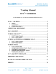
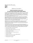
OVERTURE
User’s Manual
Manuel de l’utilisateur
Anwenderhandbuch
Manuale per l’operatore
Manual del usuario
The high quality of our products is assured by a continuous process of refinement
of their technical features. Therefore, it is possible that your product may differ
in some respect from the descriptions contained in this manual. This is not a
problem – it is an improvement. All features, descriptions and illustrations
contained herein are valid as of the date of publication.
4.
5.
Disclaimer
This manual is intended only as a guide for Antec's Computer Enclosures. For more comprehensive
instructions on installing your motherboard and peripherals, please refer to the user's manuals which
come with your components and drives.
OVERTURE User's Manual
The Antec TruePower power supply that comes with this LifeStyle series case
is equipped with Antec Low Noise Technology circuitry. Antec Low Noise
Technology is an advanced approach that achieves optimum balance between
noise reduction and necessary cooling. The power supply fans run at the lowest
speed appropriate to load and conditions as determined by a temperature
response system which outperforms previous designs. This keeps power supply
noise at a minimum and overall noise will be much lower than in cases equipped
with traditional power supplies. There are also two dedicated fan connectors
marked Fan Only from the power supply to power normal system case fans.
You may connect a regular case fan to it and have the TruePower control the
speed of the fan should you choose to install your own fan.
The Overture case is equipped with a 92mm Antec SmartCool Plus exhaust fan
at the rear of the case. This fan has a remote sensor to detect the temperature
of the case and vary the RPM of the fan accordingly. Note: DO NOT connect
the SmartCool Plus to the Fan Only connectors from the power supply. As part
of the special design of the case, we have pre-installed the SmartCool Plus
which should be powered by a standard 4-pin connector. For maximum cooling
you may choose to connect regular case fans to the regular 4-pin peripheral
connectors, but in this fashion noise will not be reduced.
[Applicable only to models designed for sale in the European Union:
TruePower
models designed for the EU include Power Factor Correction (PFC) circuitry in
accord with European standard regulation code EN61000-3-2. By altering the
input current wave shape, PFC improves the power factor of the power supply
and results in increased energy efficiency, reduced heat loss, prolonged life for
power distribution and consumption equipment, and improved output voltage
stability.]
Set
1.
2.
3.
the
Up
Take the case out of the box. Remove the Styrofoam and the plastic bag.
Place the case on a flat surface.
Note (not applicable to models designed for the European Union): Check
red power supply voltage switch setting before installation. It should be the
same as your local power voltage (115V for North America, Japan, etc. and
230V for Europe and many other countries). Change the voltage setting if
1
necessary. Failure to take this precaution could result in damage to your
equipment and could void your warranty.
Remove the two thumb screws from the top panel. Slide the panel to the
rear of the case approximately 1" or 2.5 cm and lift to remove it. Set the
panel safely aside. Note: Please don't try to use your fingernails to pry or
lift the panel.
Inside the case you should see the power supply, some wiring with marked
connectors (USB, PWR etc.), an installed I/O panel and a power cord.
You will also find a bag of hardware (screws, brass standoffs, plastic
stands, etc.).
Motherboard Installation
This manual is not designed to cover CPU, RAM, or expansion card installation.
Please consult your motherboard manual for specific mounting instructions and
troubleshooting.
1.
2.
3.
4.
5.
6.
Make sure you have the appropriate I/O panel for your motherboard. If
the panel provided is not suitable for your motherboard, please contact
your motherboard manufacturer for the correct I/O panel.
Line up your motherboard with the standoff holes, and determine which
ones line up and remember where they are. Not all motherboards will
match with all of the provided screw holes, and this is not necessary for
proper functionality. (In other words there will likely be extra holes.)
Some standoffs may be pre-installed for your convenience.
Lift up and remove your motherboard.
Screw in the brass standoffs to the threaded holes that line up with
your motherboard.
Place your motherboard on the brass standoffs.
Screw in your motherboard to the standoffs with the provided Phillipshead screws. Your motherboard is now installed.
Power/LED Connections
The Antec TruePower supply is an ATX12V power supply. It has a single
20-pin Main Power Connector, a 6-pin AUX Power Connector and a 4-pin
+12V Power Connector to connect to the motherboard. It is backwards
compatible to previous ATX form factor power supplies. If your motherboard
does not support the AUX Power Connector or the +12V Power Connector,
you can still use this power supply.
The power supply is also equipped with a 3-pin fan signal connector. You may
connect it to one of the fan connectors on your motherboard to monitor the
speed of the rear power supply fan through your motherboard BIOS or through
the monitoring software that comes with your motherboard. Note: The speed of
the fan may be as low as 1200 RPM when temperatures are low. At these
speeds some motherboards may not be able to properly detect the fan speed
and may generate false warnings of fan failure. Please refer to your
motherboard manual for proper fan monitoring set up.
1.
2.
Connect the 20-pin ATX power connector (and AUX or +12V connectors
if appropriate) to your motherboard.
The Reset switch (labeled RESET SW) connects to your motherboard at
2
3.
4.
5.
the RST connector. The colored wire should be attached to Pin 1 and the
black wire to ground. This applies for all of the following connectors as well.
Power Switch (labeled POWER SW) connects to the PWR connector on the
motherboard. The hard drive activity indicator (labeled HDD LED) connects
to the HDD LED header on the motherboard.
To connect the Speaker, find the mini speaker included in your tool bag and
connect it to the Speaker header on your motherboard.
To connect the blue LED-illuminated front Antec Logo, find the 4-pin male
Front Logo connector with a blue and a white wire (only) leading from the
front panel. Connect it to a 4-pin female power supply connector from the
power supply
USB Connection
There are 8 wires with connectors coming out from the front mounted USB
ports of the case.
1.
2.
3.
4.
5.
Locate the internal USB header on your motherboard. It consists of 10
pins in two rows. Note: On some motherboards one or two pins may be
marked as NC. This indicates no contact. It is an empty pin. You don't
need to use it. On some motherboards one pin may be missing on either
one or both rows. Don't worry about it. You only need to connect to 8
pins.
Consult your motherboard manual to get each of the pin-out positions.
Power Pins: There are two power pins, one on each row. They are usually
marked as Power, Vcc or +5V. Connect the two +5V connectors to the
two power pins. Each connector can go to either pin.
Ground Pins: There are two ground pins, one on each row. They are usually
marked as GROUND or GND. Connect the two GROUND connectors to the
two ground pins. Each connector can go to either pin.
Note: On some motherboards, there may be two ground pins on one row.
You don't need to use all of them. Make sure to connect one ground pin
on each row.
Data Pins: There are two plus data pins, one on each row, and two minus
data pins, one on each row. They are usually marked as USBD2+, USBD3+
and USBD2-, USBD3- or USBP2+, USBP3+ and USBP2-, USBP3- respectively.
a. Connect the (1) +D connector to any of the two plus data pins. It
can go to either of the plus pins.
b. Connect the (1) - D connector to the minus data pin in the same row
with the plus data pin that (1) +D connector has just connected to.
c. Repeat the same procedures to connect the (2) +D and (2) -D to the
motherboard. Make sure they are in the same row.
IEEE 1394 (FireWire, I-Link) Connection
There are six wires with connectors coming out from the front-mounted IEEE
1394 port of your case. They consist of 2 sets of twisted pair cables; TPA
(Twisted Pair A) and TPB (Twisted Pair B), a power cable (VP), and a ground
cable (VG).
1.
2.
3.
Locate and identify the pin-out of the IEEE1394 port on your motherboard.
Power Pin: Connect the VP connector to it.
Ground Pin: Connect the VG connector to it.
3
4.
Data Pins: There are two sets of data pins. Each set consists of a plus and
a minus pin. They are usually marked as TPA+ and TPA-, TPB+ and TPB-.
a. Connect the TPA+ connector to the TPA+ data pin and TPA- connector
to the TPA- data pin.
b. Connect the TPB+ connector to the TPB+ data pin and TPB- connector
to the TPB- data pin.
Audio Connection
There is an Intel standard 10-pin connector (with also 8 individual wires with
individual connectors) attached to a gray wire leading from the front panel
speaker and microphone connection. If your motherboard supports Intel's
standard onboard audio connector, you can plug the 10-pin connector directly
onto the board. For non-Intel standard audio connections, you will need to plug
the 8 individual connectors into the motherboard.
Instructions for non-standard audio connections
1. Locate the internal audio connectors from your motherboard or sound card.
2. Consult your motherboard or sound card manual for the pin-out positions.
3. Microphone Power Pin: Connect the MIC connector to this pin.
4. Microphone Input Pin: Connect the MIC-BIAS connector to this pin.
5. Ground Pin: Connect the AUD GND connector to this pin.
6. Front Right Speaker Out Pin: Connect the R-OUT connector to this pin.
7. Front Left Speaker Out Pin: Connect the L-OUT connector to this pin.
8. Rear Right Speaker Out Pin: Connect the R-RET connector to this pin.
9. Rear Left Speaker Out Pin: Connect L-RET connector to this pin
10. Speaker Ground Pin: Connect the SPK-GND connector to this pin.
Note: Your motherboard may not support rear speaker output. In this case,
you do not need to connect R-RET and L-RET.
3.5" Device Installation
There are two 3.5" external drive bays on the front bezel. The drive bays are
right above the power supply fastened by two screws. Remove the screws and
slide the drive cage out.
1.
2.
3.
4.
Remove the drive bay cover from the bay you intend to install your 3.5"
device. You will have to unscrew 2 screws to remove the drive cover
assembly.
Mount your floppy drive or other external device into the drive bay. Repeat
the same procedure for the other drive as necessary.
Slide and lock the drive tray back into the case.
Find a small 4-pin white power connector on the power supply and connect
it to the male 4-pin connector on the device.
There are 3 internal drive bays in a cage right in front of the 92 mm exhaust
fan. The drive cage is fastened to the case by two screws.
1.
2.
Remove the screws, slide the cage forward and place the drive cage on a
flat surface.
Mount your hard drive or other internal 3.5" device into the drive tray
through the rubber grommets with the special screws provided. Don't
over-tighten. Over-tightening the screws will harm the vibration and noise
4
3.
4.
reducing ability of the rubber grommets. We suggest having the connector
side of the drives facing the front of the case.
Find a 4-pin white Molex connector on the power supply and connect it to
the male 4-pin connector on the device.
Repeat the same procedure for the other drives as necessary.
Antec Quality 3-Year parts and labor warranty (A3Q)
See details at: http://www.antec-inc.com/warranty.html
5.25" Device Installation
There are two external 5.25" drive bays in a drive cage behind the front bezel.
1.
2.
3.
4.
5.
6.
To remove the 5.25" drive cage:
a. On the top of the cage, there's a quick-release lever with a release
button on top. Press this button down, and swing the quick-release
lever to the right. (This assumes you are at the rear of the case and are
facing forward.)
b. Hold the drive cage with one hand. On the bottom of the cage, there's
a metal release tab. Squeeze this tab upwards with your other hand,
and slide the cage towards the rear of the case.
Remove the drive bay cover from the bay you intend to install your 5.25"
device. To do so you must unscrew the drive cover from the cage.
Install your CD-ROM or other device to the drive bay with the screws provided.
Repeat the same procedures for the other drive as necessary.
To reinstall the 5.25" drive cage: Squeeze the metal release tab upwards
while sliding the cage towards the front of the case. Press the release
button (on top of the quick-release lever.) Swing the quick-release lever to
the left, and it will lock into position. The release button will click when the
lever is fully locked.
Connect a large 4-pin white connector from the power supply to the male
4-pin connector on the device.
Fan Installation
The case has one 92mm SmartCool Plus fan mounted in the rear of the case. It
is installed so that the air is blowing out of the case. Connect a regular 4-pin
Molex connector from the power supply to the connector on the fan. Please DO
NOT connect SmartCool Plus to TruePower's Fan Only connector since the Fan
Only connectors are designed to power standard fans only. Attaching
thermally-controlled fans to these connectors will likely result in unpredictable
and undesired behavior.
The SmartCool Plus is a thermally controlled fan which comes with a remote
sensor to detect the temperature inside the case. Find an appropriate location
for the sensor so that the fan can automatically adjust its speed according to
case temperature changes. We recommend our users to place the sensor near
the CPU, VGA or hard drives.
Washable Air Filter Maintenance
There is a washable air filter at the front left side of the case. Push the release
tab to release it. We recommend washing the air filter as often as required by
environmental conditions, at least once a month initially. Failure to keep the
installed air filter clean will result in higher system temperatures and possible
system stability problems.
5
6
Overture
Piano Black Quiet Media Case
Drawing
Number
Description
1
Top Panel
2
Expansion slot cover
3
I/O Panel
4
Internal 3.5" Drive Cage
5
92mm SmartCool Plus
6
Power Connector
7
5.25" Drive cage
8
Front Bezel
9
5.25" Drive Bay Cover
10
Power Button
11
Reset Button
12
3.5" Drive Bay Cover
13
Front Ports
14
Power Supply
15
Washable Air Filter
16
External 3.5" drive cage