1
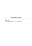
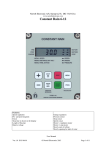
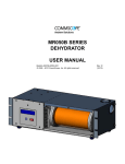
TRAINING MANUAL ECO3™ INSTALLATION Training Manual ECO3™ Installation In this module we will be discussing the following topics: WHAT YOU NEED...................................................................................... 2 ♦ ♦ ♦ TOOLS................................................................................................................... 2 EQUIPMENT........................................................................................................ 2 OTHER MATERIALS......................................................................................... 2 ADDITIONAL EQUIPMENT..................................................................... 3 INSTALLATION.......................................................................................... 3 WIRING THE ECO3™ ................................................................................ 4 ECO3™ Single Channel........................................................................................ 5 ECO3™ Dual Channel.......................................................................................... 6 WIRING AN EXTERNAL OVERRIDE RELAY..................................... 8 ECO3™ Single Channel........................................................................................ 8 ECO3™ Dual Channel.......................................................................................... 9 WIRING NOTES.......................................................................................... 9 SAFETY SWITCHES ........................................................................................ 10 CONDENSOR FAN RUN FROM STAGE 1 ................................................... 10 PUMP DOWN SOLENOIDS............................................................................. 11 COMPRESSOR PROOFING RELAYS........................................................... 12 VOLTAGE BACK FEED .................................................................................. 13 INSTALLATION CHECKLIST............................................................... 15 REMOVING THE ECO3™ ....................................................................... 16 MANUAL & INSTALLATION STICKER ............................................. 17 REVIEW...................................................................................................... 18 ©Copyright 1986 – 2006 Page 1 of 18 Smartcool Systems Inc. All Rights Reserved TRAINING MANUAL ECO3™ INSTALLATION WHAT YOU NEED ♦ TOOLS List of tools that will be required are: ♦ ♦ ♦ ♦ ♦ ♦ ♦ ♦ ♦ Cordless Drill Measuring Tape Small Level Wire Cutters Wire Strippers Crimper Screw Drivers Pliers Needle Nose Pliers ♦ EQUIPMENT ♦ ♦ ♦ ♦ ECO³™(s) Transformer(s) Fuse Holders Fuses ♦ OTHER MATERIALS There are a number of additional material pieces that will be required for the installation. These are: ♦ ♦ ♦ ♦ ♦ ♦ ♦ ♦ Wire (3 wire insulated, minimum 20AWG, 7mm) Wire (2 wire insulated, minimum 20AWG, 6mm) Wire markers Wire Ends Self tapping metal screws Cable Ties Conduit (if required) Relays (if required) ©Copyright 1986 – 2006 Page 2 of 18 Smartcool Systems Inc. All Rights Reserved TRAINING MANUAL ECO3™ INSTALLATION ADDITIONAL EQUIPMENT A certified 24VAC power supply (not supplied) is required for the unit. It is recommended to put an in-line fuse (250V/1A) from the power supply to the ECO³™ (see wiring diagrams). It is also recommended to place an in-line fuse (250V/5A) onto each of the incoming controls voltages to protect the ECO3™ from power surges that might harm its internal circuitry (see wiring diagrams). Damage due to power surges is not covered by the manufacturer warranty. INSTALLATION Safety Warning ! 3 Installation and maintenance of the ECO ™ must be carried out at 3™ all times by suitably qualified persons. The ECO must be installed in strict compliance with the national wiring rules. 3 The 24 VAC power supply to the ECO ™ must be protected by a suitable switch fuse or circuit breaker. The back plate of the ECO3™ is attached to a flat surface via four screws. The unit is then inserted onto the back plate and pushed up until it clicks into place. If theft is not a concern, the locking mechanism can be bent to make it easier to remove once installed or the backplate can be installed upside down. The unit may then be wired into the system via the cable housing on the bottom of the ECO3™ (see wiring instructions later in this manual). ©Copyright 1986 – 2006 Page 3 of 18 Smartcool Systems Inc. All Rights Reserved TRAINING MANUAL ECO3™ INSTALLATION WIRING THE ECO3™ Safety Warning: For USA and Canada, the ECO3™ must be connected to a class 2 power supply or class 2 transformer. If installed outside, the transformer must also have an IP65 rating. The ECO3™ requires a 24 VAC power supply to operate. recommended to fuse it with a 1 Amp fuse. It is This supply is via a 24 VAC isolation transformer and is powered from the control circuit in the air conditioning or refrigeration system. The power supply should be connected to the “24 VAC” terminals as shown below. ©Copyright 1986 – 2006 Page 4 of 18 Smartcool Systems Inc. All Rights Reserved ©Copyright 1986 – 2006 Page 5 of 18 Smartcool Systems Inc. 24V Stage 1 It is madatory that a glass inline fuse be used A maximum of 5 Amp (250V) is required Installation of ESM ECO3™ Single Channel unit Fuse 5 Amp (250V) maximum Mounted Externally to ESM ECO3™ unit NOTE: If the fuses are not installed all warranties will be void 24V Power supply input Neutral to match stage 1 C1 Stage 1 compressor contactor Located inside ESM ECO3™ Unit enclosure NOTE: It is suggested you use Din rail mounted In line glass fuses or an inline snap connection glass fuse holder like the one depicted above (if outside be sure the holder is waterproof) Eco3™ Stage 1 Contact TRAINING MANUAL ECO3™ INSTALLATION ECO3™ Single Channel All Rights Reserved TRAINING MANUAL ECO3™ INSTALLATION ECO3™ Dual Channel ©Copyright 1986 – 2006 Page 6 of 18 Smartcool Systems Inc. All Rights Reserved TRAINING MANUAL ECO3™ INSTALLATION To enable servicing a switch fuse or circuit breaker with a minimum current rating of 1Amp should be installed in the mains supply (240VAC/110VAC) to the 24 VAC step down transformer. The wiring installation of the ECO3™ must be carried out, at all times, by qualified technicians and must comply with all statutory and advisory codes relevant to the locality and environment. The unique circuitry of the ECO3™ enables it to control and switch loads with supply voltages ranging from 24 volts to 240 volts by utilizing interface relays to switch loads. Warning 3 The inputs to a ECO ™ must be the same voltage and the same phase. ! The maximum permissible voltage to be applied to the 3 ECO ™ terminals is 240Vac. The ECO3™ is connected into the control circuits of the refrigeration and air conditioning systems and therefore only low current (Amperage) capacity wiring (minimum of 1.5 mm) cable is required. The installation of the ECO3™ should be treated as the installation of an additional switch connected into the control circuit in series with and after the primary controller, either the thermostatic or pressure control. Three connections are required for each channel. A control input, control output and a reference wire connected to the system neutral or return side of the control circuit as outlined in the previous page diagram. Three wires per control circuit are required as shown in the above drawing. (It is advisable to use three different colours.) Connect one wire from the control thermostat or low pressure control to the IN terminal on the ECO3™ channel. Connect one wire from the N/C terminal on the ECO3™ Channel to the oil safety switch or directly to the motor starter if an oil safety switch is not fitted. ©Copyright 1986 – 2006 Page 7 of 18 Smartcool Systems Inc. All Rights Reserved TRAINING MANUAL ECO3™ INSTALLATION Finally connect the reference wire from the (N) terminal on the ECO3™ Channel to the return/ Neutral side of the contactor coil. Be sure to reinstall the wiring cover to preserve the IP rating and to have the certification label with the product at all times. WIRING AN EXTERNAL OVERRIDE RELAY To add an extra level of safety into an ECO3™ installation, a normally closed relay actuated by a thermostat can be inserted between the power supply and the ECO3™ with the thermostat situated in the controlled space (see below drawings). The thermostat is set to an appropriate temperature. Once this temperature is exceeded, power to the ECO3™ will be cut off and all control reverts to the primary controller until the temperature returns below the temperature again. This then acts like the Y2 Override function on an ESM™ or one of the override terminals available on a SIM. ECO3™ Single Channel ©Copyright 1986 – 2006 Page 8 of 18 Smartcool Systems Inc. All Rights Reserved TRAINING MANUAL ECO3™ INSTALLATION ECO3™ Dual Channel ESM ECO3™ Stage 1 Contact 24V Power supply input ESM ECO3™ Stage 2 Contact NOTE: If the fuses are not installed all warranties will be void Fuse 5 Amp (250V) Mounted Externally to ESM ECO3™ unit Located inside ESM ECO3™ Unit enclosure It is madatory that a glass inline fuse be used A maximum of 5 Amp (250V) is required A thermostat activated relay can be installed to cut power to the ESM ECO3™ if the controlled space temperature exceeds the a certain level. Once the temperature returns to below the set temperature, power to the unit is restored and savings begin again. Stage 1 T Stage 2 C1 Stage 1 Compressor Contactor C2 Stage 2 Compressor Contactor Neutral to match stages 1 & 2 24V NOTE: It is suggested you use Din rail mounted In line glass fuses or an inline snap connection glass fuse holder like the one depicted above (if outside be sure the holder is waterproof) Installation of ESM ECO3™ Dual Channel unit With External Temperature Override WIRING NOTES The wiring between different systems, manufacturers and types of units can be significantly different. Knowing where and how to insert the ECO³™ into the control circuit correctly is important for the success of the project. In this module, we will look at a number of scenarios for where and how the ECO³™ should be wired into the control circuit. It is important to remember that: The ECO³TM must know at all times when capacity is being utilized by the primary controller. If power to a channel drops off as additional capacity is added, a relay can be used to ensure the ECO³TM sees all the capacity that is being used. The ECO³TM looks for a constant signal. If the existing controller uses a pulse signal, then timers and/or relays must be used to ensure it sees a constant signal. ©Copyright 1986 – 2006 Page 9 of 18 Smartcool Systems Inc. All Rights Reserved TRAINING MANUAL ECO3™ INSTALLATION If the existing controller has a feedback loop to ensure compressors are running when it has told them to, then relays must be used to ensure it still sees a signal when the ECO³TM has put a unit into save. Also remember that the Normally Closed contact on the ECO³™ is the preferred contact as it helps ensure that the unit “fails to safe” should there be a malfunction of power issue to the ECO³™. SAFETY SWITCHES Within the control circuit, there will be a number of safety switches that are there to ensure that the system is operating properly and that the expensive pieces of equipment, like the compressors, are not damaged should an issue arise. Typically, the ECO³™ should be wired before these safety circuits to ensure they continue to operate as expected. Some that you will see are high pressure switches, low pressure switches, oil pressure switches and compressor proofing relays. CONDENSOR FAN RUN FROM STAGE 1 On some units, the condenser fan for a two stage unit will be run from the same circuit as stage 1 of cooling. Therefore, if the ECO³™ turns off stage 1 while stage 2 is running, the condenser fan will not be running. This will cause the unit to shut down on a high pressure failure. ©Copyright 1986 – 2006 Page 10 of 18 Smartcool Systems Inc. All Rights Reserved TRAINING MANUAL ECO3™ INSTALLATION One option to solve the issue is to put the ECO³™ into manual priority of 2, 1. In this method, savings will always be applied to stage 2 when it is running. The danger in this method is if the control quickly satisfies during the save, then you will also lose some of your savings. The preferred method would be to ensure that the fan continues to get a signal even when the ECO³™ has put stage 1 into save. PUMP DOWN SOLENOIDS Some compressors are not immediately stopped or started by a coil. In some cases, a thermostat is wired to the liquid line solenoid valve. On a call for cooling, the thermostat contacts close. This causes the solenoid coil to be energized, opening the valve. Liquid refrigerant flows into the evaporator and the suction pressure rises above the lowpressure control set point. The contacts on the low-pressure control close and the compressor begins to run. When the thermostat is satisfied, its contacts open, causing the solenoid valve to close. This stops refrigerant flow into the evaporator. As the compressor continues to run, refrigerant is pumped out of the evaporator coil and suction pressure falls. When the suction pressure reaches the cut-out setting on the low-pressure control, its contacts open, stopping the compressor. This removes all refrigerant from the low side of the system during the off-cycle. ©Copyright 1986 – 2006 Page 11 of 18 Smartcool Systems Inc. All Rights Reserved TRAINING MANUAL ECO3™ INSTALLATION In these circumstances, the ECO³™ is wired to the solenoid rather than to the compressor coil. COMPRESSOR PROOFING RELAYS Many manufacturers have now added proofing relays so their controller knows whether or not the compressor (or compressor capacity controller) they called for actually started running. This is so that their control can react immediately to compressors or capacity that is not operating rather than waiting for suction pressure to be impacted enough to bring on more capacity. In many cases, these relays will then lock out the impacted unit so it will be ignored in their algorithm until repairs are done. The ECO³™ will turn off or not allow starting a compressor or compressor capacity controller that the primary controller thinks should be running. When a proofing relay exists, the primary control would now lock out that channel until it was informed of repairs. As such, we need to “fool” the proofing relay into seeing a signal during the ECO³™ off times. This requires the addition of a “fooling coil” to match the signal that would come from the regular coil. ©Copyright 1986 – 2006 Page 12 of 18 Smartcool Systems Inc. All Rights Reserved TRAINING MANUAL ECO3™ INSTALLATION VOLTAGE BACK FEED On some systems, a back feed of voltage will be present. This usually will occur in one of two ways. The first is a voltage less than the normal control voltage. Because the ECO³™ is designed to handle voltages from 24 – 240VAC, it is possible for a voltage to be detected that will not activate the compressor contactor. This can be identified by seeing the Run LED on when the compressor is not actually running. The second is a back feed voltage that appears only when the ECO³™ internal relay activates for a save period. When the circuit is broken ©Copyright 1986 – 2006 Page 13 of 18 Smartcool Systems Inc. All Rights Reserved TRAINING MANUAL ECO3™ INSTALLATION the back feed voltage now appears. This can be identified by the Save LED lighting up even though the compressor was not running when the system went into a save. This can also be identified if a large amount of save hours are being recorded with a lower amount of Run hours. The easiest way to determine if there is a problem is to force the unit off via the thermostat. Pull the Y1 wire coming from the thermostat from the terminal at the unit. Measure the voltage between the wire and common. If there is voltage there when there is no call from the thermostat either install a relay or go further down the circuit until no voltage is found. ©Copyright 1986 – 2006 Page 14 of 18 Smartcool Systems Inc. All Rights Reserved TRAINING MANUAL ECO3™ INSTALLATION INSTALLATION CHECKLIST The following installation checklist will assist in ensuring that the installation of the ECO³™ was successful. 1. Ensure the unit has 24 VAC power to it and the unit display shows ON. 2. Press the Enter button once and make sure the RUN LED lights up. 3. Press the Enter button again and make sure the Save LED lights up. 4. Press the Enter button again and make sure the Bypass LED lights up. 5. Press the Enter button again and make sure the Bypass LED light flashes. 6. Using a multi-meter when the compressor is running on the channel being tested, verify that there is control voltage between “N” and “IN” and “N” and “NC”. 7. Using a multi meter when the channel is in save verify there is control voltage between “N” and “IN” and “N” and “NO” and no voltage between “N” and “NC”. If you don’t want to wait for a save cycle, disconnect the wire from “NC” (feeding the compressor contactor or pump down solenoid) and verify there is control voltage from “N” to “IN” and no control voltage between “N” and the wire removed from the “NC” terminal. CAUTION: dangerous voltage may be present at the terminals and wires!!! These tests will verify that power is being fed from the control device (Thermostat or Pressure Switch) through the “IN” terminal and out the “NC” terminal to the compressor contactor or pump down solenoid. If there is voltage between the wire removed from the “NC” and the “N” terminal (or voltage between “N” and “NC” during a save) and no voltage between the “N” terminals and “IN”, then the wires are reversed in the circuit and the ECO3 will not work properly. Correct wiring and restart the system. 8. Repeat steps 7 and 8 if the installation is an ECO³™ Dual. 9. Verify all DIP switches are in the proper position for the site conditions. 10. Verify that any ECO³™ installed outdoors has the wiring openings facing down to maintain IP65 integrity. Seal any unused holes with RTV silicone sealant. Install bottom wiring cover and make sure there are no exposed wires outside the wiring terminals. ©Copyright 1986 – 2006 Page 15 of 18 Smartcool Systems Inc. All Rights Reserved TRAINING MANUAL ECO3™ INSTALLATION 11. Verify that the 24 VAC supply is fused with a minimum of a 1 Amp fuse. 12. Verify that the control feed to the “IN” terminal has an in-line fuse of 5 amps (250V) installed. REMOVING THE ECO3™ WARNING 3 When the ECO ™ is being used to switch mains voltages, these voltages are present on exposed metal on the PCB. Ensure that incoming voltages are switched off before the enclosure is opened. To remove the ECO3™, be sure that power to the unit and main voltages are turned off. Remove the wiring tray with the two screws. Slide a metal ruler or thin metal strip up the back of the unit to release the locking mechanism. ©Copyright 1986 – 2006 Page 16 of 18 Smartcool Systems Inc. All Rights Reserved TRAINING MANUAL ECO3™ INSTALLATION Once released, the unit should push down and then come off of the mounting bracket. MANUAL & INSTALLATION STICKER Be sure to install the installation sticker close to the ECO³™ and leave a copy of the user manual with the Customer. ©Copyright 1986 – 2006 Page 17 of 18 Smartcool Systems Inc. All Rights Reserved TRAINING MANUAL ECO3™ INSTALLATION REVIEW ©Copyright 1986 – 2006 Page 18 of 18 Smartcool Systems Inc. All Rights Reserved