1
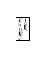
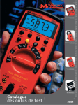
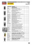
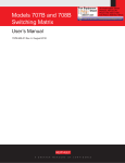
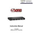
pn2728873_cover_press.pdf
8/23/2006
2:37:05 PM
DM73C
DM73C
Digital
Multimeter
Visit www.amprobe.com for
• Catalog
• Application notes
• Product specifications
• Product manuals
Pen Style DMM
C
M
Y
CM
Users Manual
MY
· Manual de uso
· Mode d'emploi
· Bedienungshandbuch
· Manuale d'Uso
CY
CMY
K
Please Recycle
99 Washington Street
Melrose, MA 02176
Fax 781-665-0780
TestEquipmentDepot.com
1
V
Ω
CAT III - 300V
CAT II - 600V
MAX
OFF
V
Ω
2
SHIFT
DC
AC
4
0
10
20
5
30
H S
mV
Mk Ω
+
H
3
DM73C
DIGITAL
MULTIMETER
COM
6
DM73C
Digital Multimeter
Users Manual
• Manual de uso
• Mode d’emploi
• Bedienungshandbuch
• Manuale d’Uso
PN 2728873
August 2006
99 Washington Street
Melrose, MA 02176
Fax 781-665-0780
TestEquipmentDepot.com
©Amprobe® Test Tools.
All rights reserved. Printed in Taiwan.
DM73C
Users Manual
• Manual de uso
• Mode d’emploi
• Bedienungshandbuch
• Manuale d’Uso
English
English
Digital Multimeter
99 Washington Street
Melrose, MA 02176
Fax 781-665-0780
TestEquipmentDepot.com
WARRANTY
Your Amprobe® product will be free from defects in material and
workmanship for 1 year from the date of purchase. This warranty
does not cover fuses, disposable batteries or damage from
accident, neglect, misuse, alteration, contamination, or abnormal
conditions of operation or handling. Resellers are not authorized to
extend any other warranty on Amprobe’s behalf. To obtain service
during the warranty period, return the product with proof of
purchase to an authorized Amprobe® Test Tools Service Center or
to a Amprobe® dealer or distributor. See Repair Section above for
details. THIS WARRANTY IS YOUR ONLY REMEDY. ALL OTHER
WARRANTIES - WHETHER EXPRESS, IMPLIED OR STAUTORY
- INCLUDING IMPLIED WARRANTIES OF FITNESS FOR A
PARTICULAR PURPOSE OR MERCHANTABILITY, ARE HEREBY
DISCLAIMED. MANUFACTURER SHALL NOT BE LIABLE FOR
ANY SPECIAL, INDIRECT, INCIDENTAL OR CONSEQUENTIAL
DAMAGES OR LOSSES, ARISING FROM ANY CAUSE OR
THEORY. Since some states or countries do not allow the exclusion
or limitation of an implied warranty or of incidental or consequential
damages, this limitation of liability may not apply to you.
CERTIFICATIONS AND PRECAUTIONS
■ The DM73C instrument is UL, cUL, and EN61010-1 certified for
Installation Category II – 600V and Category III – 300V. It is
recommended for use with local level power distribution,
appliances, portable equipment, etc, where only smaller transient
overvoltages may occur, and not for primary supply lines, overhead
lines and cable systems. ■ Do not exceed the maximum overload
limits per function (see specifications) nor the limits marked on the
instrument itself. Never apply more than 600VDC between the test
lead and earth ground.■ Exercise extreme caution when:
measuring voltage >20V // servicing CRT equipment. ■ Inspect
DMM, test leads and accessories before every use. Do not use any
damaged part. ■ Never ground yourself when taking
measurements. Do not touch exposed circuit elements or probe
tips. ■ Do not operate instrument in an explosive atmosphere.
EXPLANATION OF SYMBOLS
DANGER High
Voltage
Direct Current
ATTENTION
Refer to Manual
Alternating Current
This Instrument has
double insulation
Protective Conductor
Terminal
INTRODUCTION
The DM73C is a probe-type digital multimeter capable of
measuring DC and AC voltage, resistance, diode and continuity. Its
controls are: Volts (V), Ohms ( Ω ), Diode Test and Continuity
Beeper ( ), On- Off, AC/ DC and Hold. (See page 3) 1. V - Ω
input. 2. Function selector. 3. HOLD button. 4. SHIFT button for
AC / DC or Diode /Continuity. 5. LCD Display. 6. COM input.
1
MEASURING PROCEDURES
Note: When connecting or disconnecting test leads to or from a
circuit, always first turn off power to the circuit under test and
discharge all capacitors.
DC / AC Voltage Measurement
Set the Function switch to “V”. Select AC or DC by pressing the
mode selector button (AC or DC is displayed). Connect the
instrument to the circuit and read the measured voltage in the
display.
Resistance Measurement
Set the Function switch to “ Ω ”. Connect the instrument across the
resistance and read the value in the display. When measuring high
resistance values, take care not to touch the test leads.
Continuity Measurement
Set the Function switch to Ω . Press the mode selector button once,
so that appears ( ) in the LCD. Connect the instrument across the
device or wire to be tested. Beeper will sound when continuity is
established. The beeper also sounds when changing functions,
modes, or for Probe Hold.
Diode Measurement
Set the Function switch to Ω . Press the mode selector button twice,
so that appears ( ) in the LCD. Connect the instrument across
the device to be tested. The forward voltage drop of a good diode is
about 0.6V. An open or reverse biased diode will read “OL”.
Data Hold
Push the HOLD button to “freeze” the measurement reading and
then remove the test leads while the reading remains displayed.
HOLD is useful when it is necessary to pay very close attention to
your work. Pushing the HOLD button again releases the display.
2
Automatic Shutdown
This function causes the meter to enter power saving mode after
approximately 10 minutes. Disable automatic shutdown by holding
the shift button down while turning the meter on.
MAINTENANCE
In Case of Difficulties In the case of improper operation of the
meter, first review the operating instructions for possible errors in
operation. Inspect and check test leads for continuity. Check the
” symbol appears when
condition of the batteries. The battery “
the voltage falls below the level where accuracy is guaranteed.
Replace batteries immediately.
Battery Replacement
Warning: In order to avoid electrical shock,
remove the test lead before opening the
case. To replace the batteries ( 2 – LR44)
unscrew the battery hatch screw and remove
the old batteries. Install the new batteries
observing the diagram in the battery area.
Cleaning Procedure
Gently wipe dirt from the surface of the unit with a soft cloth
moistened with a small amount of water or neutral cleanser. Do not
use benzene, alcohol, acetone, ether, paint thinner, lacquer or
ketone solvents on the units, under any circumstances as these
may cause deformation or discoloration.
REPAIR
All test tools returned for warranty or non-warranty repair or for
calibration should be accompanied by the following: your name,
company’s name, address, telephone number, and proof of
purchase. Additionally, please include a brief description of the
problem or the service requested and include the test leads with the
meter. Non-warranty repair or replacement charges should be
remitted in the form of a check, a money order, credit card with
3
expiration date, or a purchase order made payable to Amprobe®
Test Tools.
In-Warranty Repairs and Replacement – All Countries
Please read the warranty statement and check your battery before
requesting repair. During the warranty period any defective test tool
can be returned to your Amprobe® Test Tools distributor for an
exchange for the same or like product. Please check the “Where to
Buy” section on www.amprobe.com for a list of distributors near
you. Additionally, in the United States and Canada In-Warranty
repair and replacement units can also be sent to a Amprobe® Test
Tools Service Center (see below for address).
Non-Warranty Repairs and Replacement – US and Canada
Non-warranty repairs in the United States and Canada should be
sent to a Amprobe® Test Tools Service Center. Call Amprobe® Test
Tools or inquire at your point of purchase for current repair and
replacement rates.
In USA
In Canada
Amprobe® Test Tools
Amprobe® Test Tools
Everett, WA 98203
Mississauga, ON L4Z 1X9
Tel: 888-993-5853
Tel: 905-890-7600
Fax: 425-446-6390
Fax: 905-890-6866
Non-Warranty Repairs and Replacement – Europe
European non-warranty units can be replaced by your Amprobe®
Test Tools distributor for a nominal charge. Please check the
“Where to Buy” section on www.amprobe.com for a list of
distributors near you.
European Correspondence Address*
Amprobe® Test Tools Europe
P.O. Box 1186 / 5602 BD Eindhoven / The Netherlands
*(Correspondence only – no repair or replacement available from
this address. European customers please contact your distributor.)
99 Washington Street
Melrose, MA 02176
Fax 781-665-0780
TestEquipmentDepot.com
4
SPECIFICATIONS
General Specifications
Display: 3- 3/ 4 digit LCD, 3400 count
Measuring rate: 2.5/ second nominal
Bargraph: 34 segments – updated 20 readings per second
Operating Temp. range: 0 to 40° C, 80% RH
Storage Temp. range: -20 to 60° C, 70% RH
Environmental: Intended for Indoor use, Altitude up to 2000 m.
Measurement Accuracy: x0.1/ C°
Batteries: 2x LR44, SR44 or S76
Life: 100 hours nominal
Auto Power Off: after 10 minutes
Dimension: 7.8” x 1.1” x 1.4”
Weight: .21 lb.
Accessories: Operating manual, test lead with alligator clip, 2
batteries (installed), spare tip.
Approvals:
Safety: Conforms to EN61010- 1: Cat II - 600V, Cat III – 300V ;
Class 2, Pollution degree II; UL3111-1. EMC: Conforms to
EN61326-1.
The TL73B test lead and alligator clip is UL approved for use only
with the DM73C.
This product complies with requirements of the
following European Community Directives: 89/ 336/
EEC (Electromagnetic Compatibility) and 73/ 23/
EEC (Low Voltage) as amended by 93/ 68/ EEC (CE Marking).
However, electrical noise or intense electromagnetic fields in the
vicinity of the equipment may disturb the measurement circuit.
Measuring instruments will also respond to unwanted signals that
may be present within the measurement circuit. Users should
5
exercise care and take appropriate precautions to avoid misleading
results when making measurements in the presence of electronic
interference.
Electrical Specifications
Accuracy at 23°C ± 5°C, < 75 % RH, guaranteed for one year.
DC Volts
Ranges: 340mV, 3.4, 34, 340V, 600V
Accuracy: ± (0.5% rdg + 2 dgt)
Input Impedance: 340 mV range: >100MΩ , other ranges: 10MΩ
Protection: 600VDC or AC rms
AC Volts
Ranges: 3.4V, 34, 340, 600V
Accuracy: ± (1.5 % rdg + 8 dgt) (50 - 500Hz)
Input Impedance: 10MΩ
Protection: 600VDC or AC rms.
Resistance
Ranges: 340 Ω , 3.4, 34, 340 kΩ , 3.4, 34 MΩ
Accuracy:
340Ω - 340kΩ: ± (1.0 % rdg + 4 dgt)
3.4MΩ: ± (1.5 % rdg + 4 dgt)
34 MΩ: ± (3.0 % rdg + 5 dgt)
Max. open circuit voltage: 340Ω range - 1.2V; all others: - 0.45V
Protection: 500VAC or DC.
Diode Test
Range: 3.4V
Accuracy: ± (2.0%rdg + 3 dgt)
Resolution: 0.1mV in 3.4V range
Short circuit current: 1.0mA
Max open circuit voltage: 3.0VDC
Audible indication: < 0.2V
Overload prot.: 500VDC or AC rms
6
Continuity
Display response: <0.5s
Continuity threshold: ≤ 35 Ω
Overload prot.: 500VDC or AC rms
Accessories / User Replaceable Parts
TL73B Test lead with alligator clip
VC11 Vinyl Case
TP73B Replaceable Probe tip
Battery Type SR44, LR44, or S76
99 Washington Street
Melrose, MA 02176
Fax 781-665-0780
7
TestEquipmentDepot.com