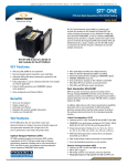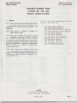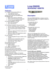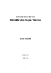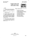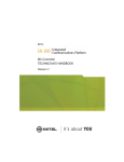
1
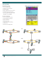
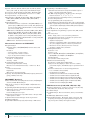
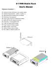
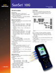
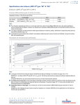
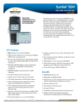
SUNRISE TELECOM®
®
SunSet 10G
with Electrical Interface Ports
Technical Specification
With support for twelve different optical and electrical rates from
1.5/2 Mbps through 10 Gbps, the SunSet 10G covers all test interfaces
for core and metro SONET/SDH rings and their tributaries. With all-inclusive solutions for SDH, SONET, PDH, T-carrier, electrical and optical, the
SunSet 10G increases testing efficiency, consolidates training, and saves
money. And as optical networks reach across international boundaries,
The SunSet 10G
the SunSet 10G can turn up SDH and SONET services around the world.
Field engineers can verify proper hands-offs at SONET/SDH gateways; test network continuity across the 10G backbone
network and analyze its tributaries; and test the OC-192/STM-64 wavelengths in the DWDM network. Applications include basic
end-to-end performance testing with BERT, inservice performance monitoring, and simulating abnormal conditions to check the
network’s response. Regardless of line rate or transmission standard, everything from basic BERT to advanced APS and pointer
testing is right at your fingertips.
KEY features
• 2 kg handheld test set for SONET and SDH
• SONE T and SDH testing from ST S -1/STM-0 to
OC-192/STM-64
• T-carrier and PDH testing from DS1/E1 to E4
• Dual wavelength transmitter up to 2.5 Gbps
• Mapping/demapping from STS-192c, SPE/VC4-64c Bulk
down to VT1.5, VT2, VC11, VC12
• Mux testing (SDH to SDH, SDH to PDH, SONET to SONET,
SONET to T-carrier)
• SONET/SDH overheard byte access and control
• Battery operated: one hour operating time at 10 Gbps
• Economical for wide deployment
• Windows Remote Control
• Verify network continuity with BER testing
• Easily detect SDH/SONET errors and alarms with LEDs and
Well-organized results
• Confirm proper frequency and power level
• Monitor pointer movement in the network and adjust
pointer values to stress network elements
• Identify network synchronization problems by connecting
the external clock input to the synchronization timing
source of the network
• Check the network’s automatic protection switch (APS)
function and measure network switchover time
• Troubleshoot problems across multiple network operators
with Tandem Connection Monitoring (TCM)
benefits
• SONET/SDH/PDH/T-Carrier feature-rich
• Lightweight and highly portable
• Eliminates the need for multiple and heavier instruments
without compromising test features or accuracy
• Intuitive and easy-to-use
• Cost-effective and future proof
• Increases efficiency
• Consolidates training and shortens learning curve
• Handles multiple tasks including installation, maintenance,
troubleshooting, and commissioning
www.sunrisetelecom.com
applications
SS10G+ OverHead Control Screen Shot
Out-of-Service testing
• End-to-end BER testing
• Network element verification
• Overhead control
• Pointer adjustment and test sequences
• Propagation delay measurements
• Mux testing (SDH-SDH, SONET-SONET,
PDH-SDH, T-carrier-SONET)
In-service monitoring
• In-service performance analysis
• Overhead monitor and decode
• Pointer monitoring
• APS measurements
• Tandem Connection monitoring
• Tributary scan
• With splitter or through mode
CORE
Tx
ADM
10G DWDM
RING
Rx
ADM
Tx
ADM
ADM
ADM
ADM
ADM
Tx
Rx
Rx
METRO
Tx
ADM
2.5G DWDM RING
Rx
ADM
ADM
ADM
ADM
OC-48/STM-16
Optical Ring
Through mode
ACCESS
T1/E1
2
Rx
ADM
ADM
Tx
ADM
OC-192/STM-64
RING
Rx
SunSet ® 10G with Electrical Interface Ports
ADM
SPECIFICATIONS
Test Interfaces
SDH/SONET
10G Optical (STM-64/OC-192)
Port/Connector: FCUPC or SCUPC
Mode: Single Mode compatible
Line coding: NRZ
Complies to Telcordia GR-253 (September 2000 issue) and ITU-T
G.691
Transmitter
Clock source
Internal: 9.95328 Gbit/s ± 4.5 ppm
Receive: Recovered from received signal
External: Synchronization to external 2.048 MHz or 2.048 Mbit/s
(SDH), 1.544 Mbit/s (SONET)
Output power range
1550 nm Short Reach: -4 to -1 dBm
1310 nm Intermediate Reach: -1 to +2 dBm
Laser Safety: IEC60825-1/2001, Class 1, 21 CFR 1040.10
and 1040.11
Extinction ratio: 8.2 dB min, 10 dB typ.
Test patterns
231-1, 223-1, All 1s, All 0s, Alt 1010, 1 in 4, 1 in 8
10 Programmable 16-bit user patterns Test pattern inversion
Receiver
Frequency recovery range: 9.95328 ± 50 ppm
Wavelength: 1290 to 1600 nm
Input power range
1550 nm Short Reach, PIN detector: -15 to 0 dBm
1310 nm Intermediate Reach, PIN detector: -17 to 0 dBm
Maximum input power: +7 dBm
52M/155M/622M/2.5G Optical (STM-0/1/4/16 OC1/3/12/48)
Port/Connector: FCUPC or SCUPC Mode: Single Mode compatible
Line coding: NRZ
Complies to Telcordia GR-253 (September 2000 issue) and ITU-T
G.957
Transmitter
Clock source
Internal
– Bit rates
51.840 Mbit/s ± 4.5 ppm
155.520 Mbit/s ± 4.5 ppm
622.080 Mbit/s ± 4.5 ppm
2.48832 Gbit/ss ± 4.5 ppm
Receive: Recovered from received signal
External: Synchronization to external 2.048 Mbit/s or 2.048 MHz
(SDH), or 1.544 Mbit/s (SONET)
Output power range
1310/1550 nm Intermediate Reach: -5 to 0 dBm
1310/1550 nm Long Reach: -2 to +3 dBm
Laser Safety: IEC60825-1/2001, Class 1, 21 CFR 1040.10 and
1040.11
Extinction ratio: 8.2 dB min, 10 dB typ.
Test patterns
223-1, 220-1, 215-1, 211-1, 29-1, 27-1, 26-1, All 1s, All 0s, Alt 1010,
1 in 4, 1 in 8
10 Programmable 16-bit user patterns Test pattern inversion
Receiver
Frequency recovery range:
51.840 Mbit/s ± 50 ppm
155.520 Mbit/s ± 50 ppm
622.080 Mbit/s ± 50 ppm
2.48832 Gbit/s ± 50 ppm
Wavelength: 1280 to 1580 nm
Input power range:
1310/1550 nm Intermediate Reach: -20 to -3 dBm
1310/1550 nm Long Reach: -27 to -9 dBm
Maximum input power:
1310/1550 nm Intermediate Reach: +3 dBm
1310/1550 nm Long Reach: -5 dBm
SDH/SONET 155M Electrical (STM-1/STS-3)
Port/Connector: 75Ω unbalanced BNC (f) Line coding: CMI
Complies to Telcordia GR-253 (September 2000 issue) & ITU-T
G.957
Transmitter
Clock source
Internal: 155.520 Mbit/s ± 4.5 ppm
Receive: Recovered from received signal
External: Synchronization to external 2.048 MHz or 2.048 Mbit/s
(SDH), via 1.544 MHz or 1.544 Mbit/s (SONET)
Pulse shape: Conforms to ITU-T G.703
Framing: Conforms to ITU-T G.707
Receiver
Frequency recovery range: 155.520 Mbit/s ± 150 ppm
Input power range
Terminate: 12.7 dB cable loss
Monitor: 20 dB resistive loss plus 12 dB cable loss
Jitter tolerance: Conforms to ITU-T G.825
SDH/SONET 52M Electrical (STM-0/STS-1)
Port/Connector: 75Ω, unbalanced BNC (f)
Line coding: B3ZS
Complies to Telcordia GR-253 (September 2000 issue) & ITU-T
G.691
Transmitter
Clock source
Internal: 51.840 Mbit/s ± 4.5 ppm
Receive: Recovered from received signal
External: Synchronization to external 2.048 MHz or 2.048 Mbit/s
(SDH), via 1.544 MHz or 1.544 Mbit/s (SONET)
Pulse shape: Conforms to ITU-R F.750-3
Framing: Conforms to ITU-T G.707 Annex A
Receiver
Frequency recovery range: 51.840 Mbit/s ± 50 ppm
Input power range
Terminate: 10.8 dB cable loss
Monitor: +3 to -26 dB resistive loss
Jitter tolerance: Conforms to ITU-T G.825
www.sunrisetelecom.com
3
PDH/T-CARRIER
139M/E4
Transmitter
Clock source
Internal : 139.264 Mbit/s ± 4.5 ppm
Receive: Recovered from received signal
Pulse shape: Conforms to ITU-T G.703
Line coding: CMI
Framing: Unframed, Framed, Structured per ITU-T G.751
Loop: Recovered from received signal
Error injection
Code, Bit, FAS
Programmable error burst 1 to 9999 count or error rate 2 x 10⁻³
to 1 x 10⁻⁹
Alarm generation: AIS, FAS RAI
Receiver
Frequency recovery range: 139.264 Mbit/s ± 150 ppm Input power range
Terminate: 12 dB cable loss
Monitor: 20 dB resistive loss plus 12 dB cable loss
Jitter tolerance: Conforms to ITU-T G.823
Impedance: 75Ω, unbalanced
Port/Connector: 75Ω, unbalanced BNC (f)
45M/DS3
Transmitter
Clock source
Internal: 44.736 Mbit/s ± 4.5 ppm
Receive: Recovered from received signal
Pulse shape: Conforms to ITU-T G.703
Line coding: B3ZS
Framing: Unframed, M13, and C-bit
Port/Connector: 75Ω, unbalanced BNC (f)
Error injection
Code, Bit, Frame, C-bit, P-bit, FEBE
Programmable error burst 1 to 9999 count, or error rate 2 x 10⁻³
to 1 x 10⁻⁹
Alarm generation: AIS, Yellow, Idle
Error injection
Code, Bit, FAS
Programmable error burst 1 to 9999 count, or error rate 2 x 10⁻³
to 1 x 10⁻⁹
Alarm generation: AIS, FAS RAI
Receiver
Frequency recovery range: 34.368 Mbit/s ± 50 ppm
Input power range
Terminate: -12 dB cable loss
Monitor: -20 dB resistive loss plus -12 dB cable loss
Jitter tolerance: Conforms to ITU-T G.823
Impedance: 75Ω, unbalanced
Port/Connector: 75Ω, unbalanced BNC (f)
2M/E1
Transmitter
Clock source
Internal: Bit rate: 2.048 Mbit/s ± 4.5 ppm
Receive: Recovered from received signal
External: Synchronization to external 2.048 MHz or 2.048 Mbit/s
Pulse shape: Conforms to ITU-T G.703 for balanced (120Ω) interfaces
Line coding: AMI, HDB3
Framing: Unframed, PCM-30, PCM-30C, PCM-31, PCM-31C conforms to ITU-T G.704
Port/Connector
120Ω (standard): balanced RJ-45 (f)
Error injection
Code, Bit, CRC-4, E-bit, FAS
Programmable error burst 1 to 9999 count, or error rate 2 x 10⁻³ to 1 x 10⁻⁹
Alarm Generation: AIS, FAS RAI, MFAS RAI
Fractional E1
Error measurements, channel configuration verification
N or M (noncontiguous) x 64 kbit/s, N=1 to 31
Set Tx and Rx channels independently
Through mode: Test pattern on selected channels; all others
through
Receiver
Frequency recovery range: 44.736 Mbit/s ± 50 ppm
Input power range
Terminate: Up to -6 dB cable loss
Monitor: +6 dB to -26 dB resistive loss
Jitter tolerance: Conforms to ITU-T G.824
Impedance
Terminate, Monitor: 75Ω, unbalanced
Port/Connector: 75Ω, unbalanced BNC (f)
Receiver
Frequency recovery range: 2.048 Mbit/s ± 50 ppm
Input power range
Terminate, Bridge: +6 to -43 dB with ALBO
Monitor: -20 dB resistive loss plus -6 dB cable loss
Jitter tolerance: Conforms to ITU-T G.823
Impedance
Terminate, Monitor: 120Ω balanced
Bridge: > 5000Ω
Port/Connector: 120Ω, balanced RJ-45 (f)
Level measurements (dBm)
34M/E3
1.5M/DS1
Transmitter
Clock source
Internal: 34.368 Mbit/s ± 4.5 ppm
Receive: Recovered from received signal
Pulse shape: Conforms to ITU-T G.703
Line coding: HDB3
Framing: Framed, Unframed, Structured per ITU-T G.742, G.751
Port/Connector: 75Ω, unbalanced BNC (f)
Transmitter
Clock source
Internal: 1.544 Mbit/s ± 4.5 ppm
Receive: Recovered from received signal
External: Synchronization to external 1.544 Mbit/s
Pulse shape: Conforms to ITU-T G.703
Line coding: AMI, B8ZS
Framing: Unframed, SF-D4, ESF. Conforms to ANSI T1.102, 107,
4
SunSet ® 10G with Electrical Interface Ports
107A, 403, and 404. Also Telcordia TR-TSY-000009 and
TR-TSY-000191.
Port/Connector: 100Ω, balanced RJ45 (f)
Error injection
BPV, Logic, CRC-6, Frame
Programmable error burst 1 to 9999 count, or error rate 2 x 10⁻³
to 1 x 10⁻⁹
Alarm generation: AIS, Yellow, Idle
Fractional T1
Error measurements, channel configuration verification
Nx64 kbit/s, Nx56 kbit/s, N=1 to 24
Set Tx and Rx channels independently
Through mode: Test pattern on selected channels; all others
through
Receiver
Frequency recovery range: 1.544 Mbit/s ± 50 ppm
Input power range
Terminate, Bridge: +6 to -36 dB cable loss
Monitor: -15 to -25 dB, resistive loss
Jitter tolerance: Conforms to ITU-T G.824
Impedance
Terminate, Monitor Mode: 100Ω, balanced
Bridge: > 5000Ω
Port/Connector
100Ω, balanced RJ-45 (f)
Level measurements (dBm)
Test Features
Test Modes
Point-to-point: Tx and Rx are set to the same rate
Unframed Mode: Disables SDH/SONET overhead or PDH/T-carrier
framing
Through Mode Operation (up to 10G)
Line through
– Passes entire signal through with no manipulation of overhead or injection of errors or alarms
– Overhead can be monitored; alarms and errors measured
Payload through
– Passes payload through
– Passes all Path overhead through
– Injects SOH errors/alarms
– Controls SOH overhead, except pointers
SDH-PDH Mux/Demux Testing
The test pattern is generated on the low or high rate port and the
BERT is measured on the opposite port. The following combinations
are applicable:
• 10G 0/139M
• 10G 0/45M
• 10G 0/34M
• 10G 0/2M
• 10G 0/1.5M • 2.5G 0/139M
• 2.5G 0/45M
• 2.5G 0/34M
• 2.5G 0/2M
• 2.5G 0/1.5M
• 622M 0/139M
• 622M 0/45M
• 622M 0/34M
• 622M 0/2M
• 622M 0/1.5M
•155M E (0)/139M
•155M E (0)/45M
•155M E (0)/34M
•155M E (0)/2M
•155M E (0)/1.5M
SDH-SDH Mux/Demux Testing
The following combinations are applicable:
• 10G 0/2.5G 0
• 10G 0/622M 0 • 2.5G 0/622M 0 • 622M 0/155M E (0) • 155M E (0)/52M E
• 10G 0/155M E (0) •2.5G 0/155M E (0) •622M 0/52M E (0)
• 10G 0/52M E
•2.5G 0/52M E (0)
MuxMode: Emulation of a mux for 1.5M, 2M, 34M, 45M, and 139M
payloads
SDH (ITU-T G.707)
Rates: STM-64 (9.9 Gbit/s), STM-16 (2.5 Gbit/s), STM-4 (622 Mbit/s),
STM-1 (155 Mbit/s), STM-0 (52 Mbit/s)
Payloads: VC4-64c, VC4-16c, VC4-8c, VC4-4c, VC4-3c, VC4-2c, VC4
Bulk, VC3 Bulk, 45M, 34M, 2M Async, 1.5M Async, VC12 Bulk,
VC11 Bulk
ITU-T Mapping
Error Injection: B1, B2, B3, FASE, MS-REI, HP-REI, LP-REI, BIP-2, Bit
Error Injection Count: Programmable error burst of 1 to 9999
Error Injection Rate: 2 x 10⁻³ to 1 x 10⁻⁹
Alarm Generation: LOS, LOF, RS-TIM, MS-AIS, MS-RDI, AU-AIS, AU-LOP, HP-RDI, HP-UNEQ, HP-PLM, HP-TIM, LP-RDI, LP-RFI, LPPLM, LP-UNEQ, LP-TIM, TU-LOM, TU-LOP, TU-AIS
Results Measurements
Errors: B1, B2, B3, FASE, MS-REI, HP-REI, LP-REI, BIP-2, Bit
Alarms: LOS, LOF, OOF, RS-TIM, MS-AIS, MS-RDI, AU-AIS, AULOP, HP-RDI, HP-UNEQ, HP-PLM, HP-TIM, LP-RDI, LP-RFI,
LP-PLM, LP-UNEQ, LP-TIM
Performance monitoring: G.821, G.826, G.828, G.829,
M.2100/2110, M.2101/M.2120
SDH Pointer: Justification, Increase, Decrease
Automatic Tributary Scan: 80 characters/line report of alarms/errors per tributary. In-service and out-of-service for 1.5M, 2M, 34M,
45M, 139M, VC3 Bulk, and VC4 Bulk inside STM1/4/16 with full
report.
SONET (Telcordia GR-253-CORE)
Rates: OC-192 (9.9 Gbit/s), OC-48 (2.5 Gbit/s), OC-12 (622 Mbit/s),
OC-3/STS-3 (155 Mbit/s), OC-1/STS-1 (52 Mbit/s)
www.sunrisetelecom.com
5
Payloads: STS-192c, STS-48c, STS-24c, STS-12c, STS-9c, STS-6c, STS-3c, STS-1, DS3, E3, VT2, E1 Async, VT1.5 Bulk, DS1 Async
Error Injection: B1, B2, B3, BIP-V, Frame, REI-L, REI-P, REI-V, Bit
Error Injection Count: Programmable error burst of 1 to 9999
Error Injection Rate: 2 x 10⁻³ to 1 x 10⁻⁹
Alarm Generation: LOS, LOF, AIS, AIS-L, RDI-L, LOP-P, AIS-P, RDI-P,
PLM-P, TIM-P, UNEQ-P, AIS-V, RDI-V, LOP-V, PLM-V, TIM-V,
UNEQ-V, LOM
Results Measurements
GR-253 Bit Performance: FC (failure counts), BER, LOPS (loss of
pattern sync), %LOPS, ES (errored seconds), %ES, SES (severely
errored seconds), %SES, UAS (unavailable seconds), %UAS, EFS
(error free seconds), %EFS
SONET defects: LOS, LOF, AIS, AIS-L, RDI-L, LOP-P, AIS-P, RDI-P,
PLM-P, TIM-P, UNEQ-P, AIS-V, RDI-V, LOP-V, PLM-V, TIM-V,
UNEQ-V, LOM, B1, B2, B3, BIP-V, Frame, REI-L, REI-P, REI-V,
FC (failure counts), ES (errored seconds), %ES, SES (severely
errored seconds), %SES, UAS (unavailable seconds), %UAS, EFS
(error free seconds), %EFS
SONET Pointer: Justification, Increase, Decrease
Measurements Common to SDH/SONET
Histogram Analysis
Graphical display of SDH/SONET/PDH/T-carriers defects and
anomalies
Resolution
– Last hour with 1 second resolution
– Last 3 days with 1 minute resolution
– Up to 57 days with 15 minutes resolution
Service Disruption Measurement
Resolution: 1 frame (125 ns)
Accuracy: < 50 ns
Propagation Delay Measurement
Round trip signal transmission delay
Measures in ns and UI (Unit Intervals) – from 6 ns to 10 sec
General
Continuous measurement
Elapsed time
Optical power level measurement
Frequency: Received, Maximum, Minimum (frequency deviation in
ppm), ± Wander, Clock slips
SDH/SONET Overhead
Monitor and Transmit Section/Regenerator Section, Line/Multiplex
Section, and Path Overhead bytes
ASCII decode of 16-byte or 64-byte HP/STS or LP/VT Path Trace
bytes (J1/J2)
Programming K1/K2 APS signaling bytes per ITU-T G.783/G.841
K1 and K2 byte capture: 20 transitions (minimum)
Time resolution: 125 ns
Linear and Ring decode of bytes
J0 Section Trace Generation: 1 byte SAPI format or 16 bytes E.164
ASCII sequence + CRC-7
S1 Synchronization Status Messages decode & generation
Path Overhead Monitor
Programmable Orderwire bytes (E1, E2) in binary or HEX format
6
SunSet ® 10G with Electrical Interface Ports
Programming of Path Overhead bytes
J1/J2 Path Trace Generation: 16 bytes E.164 ASCII sequence +
CRC-7 or 64 bytes E.164 ASCII sequence
DCC BER testing through D1 to D3 bytes or D4 to D12 bytes Pattern selection 223-1, 220-1, 215-1, 211-1
C2 signal label byte programming in binary or hexadecimal
G1 bit 5: RDI generation
User programmable path user bytes (F2, F3)
Programmable K3 (24), K4 (27) bytes (bits 1-4) for APS signaling
V5 byte: Signal label generation (bits 5-7), Extended signal label
generation/decode (K4 byte), Enhanced RDI generation/detection
Pointer Monitor: H1, H2, V1, V2 bytes
Pointer Adjustment: Programming of pointer value, NDF, and SS
bits
Pointer Test Control
Modes: Single , burst of 2-8 consecutive justifications
Select increment, decrement, or alternate the pointer value
G.783/GR-253 Pointer Test Sequences
– AU/STS or TU/VT pointer
– Sequences: Single, Burst, Phase, Transient Burst, Periodic,
87-3, 26-1, Opposite (Increase + Decrease), and Custom
– Movement: Increase, Decrease, Increase + Decrease
– Anomalies: Added, Cancel, and None
APS Timing Measurement
Resolution: 1 ms
Accuracy: 1 ms
Sensors: LOS, LOF, MS-AIS/AIS-L, MS-RDI/RDI-L, AU-AIS/AIS-P,
HP-RDI/RDI-P, TU-AIS/AIS-V, LP-RDI/RDI-V
Pass/Fail Indicator
User selectable switch and gate time
Tandem Connections Monitoring
N1, N2 bytes for High and Low Order Paths
Analysis of the data, display of data in the form of alarms,
performance figures, and APId messages as specified in ITU-T
G.707
Generation and detection of the following parameters:
– Loss of Tandem Connection (LTC)
– Incoming Error Count (IEC)
– Tandem Connection Remote Error Indication (TC-REI)
– Tandem Connection Alarm Indication Signal (TC-AIS)
– Tandem Connection Remote Defect Indication (TC-RDI)
– Tandem Connection Outgoing Defect Indication (TC-ODI)
– Tandem Connection Outgoing Error Indication (TC-OEI)
– Tandem Connection UnEquip (TC-UNEQ)
PDH Measurements (139M, 45M, 34M, 2M, 1.5M)
Typical Error Type Reports: Total error count, error rate, ES, %ES,
SES, %SES, UAS, %UAS, EFS, %EFS, AS, %AS
ITU-T G.821 Analysis
ITU-T G.826 Analysis: Based on anomalies, defects, far end indications
M.2100 Analysis (Maintenance or BIS)
Frequency Measurements: Moving bar graph of slip count, max
frequency, min frequency, frequency deviation in ppm, clock
slips, max positive wander, max negative wander
Alarm Statistics
LOS Seconds, LOF Seconds, AIS Seconds
FAS RAI Seconds (2M, 34M, 139M)
MFAS RAI Seconds (2M only)
Yellow Alarm Seconds (1.5M, 45M)
T-Carrier Measurements (DS1, E1, E3, DS3, E4)
Error Type Code (BPV), F-bit, P-bit, C-bit, FEBE, CRC-6 (DS1, DS3)
Code, Bit, FASE (E1, E2, E3, E4)
CRC-4, E-bit (E1)
Typical Error Type Reports: Total error count, error rate, ES, %ES,
SES, %SES, UAS, %UAS, EFS, %EFS, AS, %AS
GR-253 Analysis
Frequency Measurements: Moving bar graph of slip count, max
frequency, min frequency, frequency deviation in ppm, clock
slips, max positive wander, max negative wander
Alarm Statistics
LOS Seconds, LOF Seconds, AIS Seconds
FAS RAI Seconds (2M, 34M, 139M)
MFAS RAI Seconds (2M only)
Yellow Alarm Seconds (1.5M, 45M)
Error Injection
Error Type Code, Bit, FASE (2M, 8M, 34M, 139M)
CRC-4, E-bit (2M)
Code (BPV), F-bit, P-bit, C-bit, FEBE, CRC-6 (1.5M, 45M)
Programmable error burst 1 to 9999 count or error rate of 2x10⁻³
to 1x10⁻⁹
Alarm Generation
LOS, LOF, AIS (1.5M, 2M, 8M, 34M, 45M, 139M)
FAS RAI (2M, 8M, 34M, 139M)
MFAS RAI (2M only)
Yellow Alarm, Idle (1.5M, 45M)
Propagation Delay Measurement
Round trip signal transmission delay
Measures in ns and UI (Unit Intervals)
Other Features
Auto Configuration
Single button configuration
Automatically scans all test interfaces for signal
Configures test set based on received signal. Sets rate, mapping,
and test pattern
System Profiles: Store up to 100 system configurations
Battery: Built-in Li-Ion rechargeable field replaceable battery pack
Operating temperature: 0°C to 45°C [32°F to 113°F] Storage temperature: -20°C to 70°C [-4°F to 158°F] Operating humidity: 5% to 90% noncondensing
Size: 122 x 99 x 300 mm [4.8 x 3.9 x 11.8 in]
Weight: 2.2 kg [5 lbs]
Integrated tilt stand with protective rubber holster
ORDERING INFORMATION
Test Set
SS10GP-25
[These options are mutually exclusive]
SS10GP-13IR
SS10GP-15SR
10 Gb/s 1310m Intermediate Reach (24Km) Tx/Rx Pin Detector
10 Gb/s 1550m Short Reach (20Km) Tx/Rx
Pin Detector
STM-0/1/4/16 Optics Options
[These options are mutually exclusive]
SS10GP-25-SW1
SS10GP-25-DW2
SS10GP-25-DW5
2.5 GB/s 1310nm intermediate Reach Tx/Rx
2.5 Gb/s 1310 nm Intermediate Reach Tx,
1550 nm Intermediate Reach Tx, Intermediate Reach Rx
2.5 Gb/s 1310nm/1550 nm Long Reach Tx, Long Reach Rx
Optical Connector Options (SC or FC)
[These options are mutually exclusive, based on chassis selection. Must select
only one]
SS10GP-25-SC
SS10GP-25-FC
SS10GP-25 SCUPC Optical Connectors
SS10GP-25 FCUPC Optical Connectors
Accessories Options
Standard Accessories
SS10GP-101 SA140
SS10GP-RH Power Cord
SS10GP User’s Manual
AC Power Adapter
SS10GP Rubber Holster
2-Prong power cord plus ground for use in Europe (Except UK)
3-prong power cord for use in Latin America, North America, and Asia
3-prong power cord for use in United Kingdom
SS10GP-W3 SS10GP-W4 Standard 3 year warranty. [Excludes Battery and
Accessories, which are warranted for one-year]
4 year warranty [Excludes Battery and Accessories, which are warranted for one-year]
SA155-NA
SA155-UK
Display: TFT, 640 × 480 pixel color, Indoor/Outdoor readable
Soft LEDs on display: Signal, Alarm, Frame, Errors, Pointer
Rubber keypad
Network: 10/100Base-T RJ-45
Serial Port: RS-232C (V.24), RJ-11 connector
DC Power for battery charger and continuous operation
STM-64 Optics Options
SA155-EU
General
STM-64/OC-192 and STM-0/1/4/16/OC-1/3/12/
48 SDH/SONET Test Set. 1.5M/2M testing, 8-pin RJ-45 connector. 34M/45M/52M/139M/155M testing, BNC connectors.
Warranty
www.sunrisetelecom.com
7
Software Option
SW10GP-DEI Replacement
Disable Electrical Interfaces
[Must be specified with a chassis at the time of order]
Calibration Options
SS10GP-CCM Certificate of calibration with measurement data
[Must be specified at time of order]
Optical Accessories
SA501
SA502
SA503
SA507
SA508
SA509
SA511
SA512
SA521
SA523
SA524
SA531
SA541
SA545
SA551
SA555
Optical Patch Cord, SMF, FC-PC to SC-PC, 6’
Optical Patch Cord, SMF, FC-PC to SC-PC, 6’
Optical Patch Cord, SMF, FC-PC to ST-PC, 6’
Optical Patch Cord, LCUPC to LCUPC, 6’
Optical Patch Cord, LCUPC to SCUPC, 6’
Optical Patch Cord, LCUPC to FCUPC, 6’
Optical Patch Cord, SC to SC, 6’
Optical Patch Cord, SC to ST, 6’
Optical Attenuator, FC-PC, -10 dB
Optical Connector Adapter FC/PC to SC/PC
Optical Connector Adapter SC/PC to FC/PC
[Changes a SC (f) appearance to a FC (f) appearance]
Optical Attenuator, SC-PC, -10 dB
Optical Splitter, FC-PC, 90/10
Optical Splitter, FC-PC, 50/50
Optical Splitter, SC-PC, 90/10
Optical Splitter, SC-PC, 50/50
Other Accessories
SS101
SS106
SS108
SS109
SS110
SS112
SS211
SS212
SS220
SS225
SS227
SS423
SS430-WT-OPT SS434
SS436
SA155-NA SA155-UK SS10GP-RH SS10GP-101 SS10G-HC High Capacity Li-Lon Battery Pack for SunSet 10G.
AC Power Adapter. SA155-EU 2-Prong power cord plus ground for use in Europe (Except UK)
3-prong power cord for use in Latin America, North America, and Asia
3-prong power cord for use in United Kingdom
SS10GP Rubber Holster
SS10GP User’s Manual
SS10GP Hard Carrying Case
SunSet® 10G with Electrical Interface Ports
1.5M/2M*
10Base-T Port
Serial Port
External Clock
Carrying Case
Cable, Single Bantam (m) 120Ω to Single Bantam (m) 120 Ω, 6’
Cable, Single Bantam (m) 120Ω to Single 310 (m) 120Ω, 6’
Cable, Single Bantam (m) 120Ω to Alligator Clips 120Ω, 6’
Cable, Dual Bantam (m) 120Ω to 15-pin D connector (m) 120Ω, 6’
Cable, Two Single Bantams (m) 120Ω to RJ-48 8-position Modular Plug (m) 120Ω, 6’
Cable, BNC (m) 75Ω to BNC (m) 75Ω, 6’
Cable, Single Bantam (m) 120Ω to BNC (m) 75Ω, 6’
Conversion Cable, BNC (m) 75Ω to 1.6/5.6 mm (m) 75Ω, 6’
Cable, Bantam (m) 120Ω to 3-pin banana CF (m) 120Ω, 6’
Conversion Cable, BNC (m) 75Ω to probe clips
120Ω, 6’
Cable, RJ45 (m) to RJ45 (m) with shield, 6’
Sunrise Optical Cable Kit
[Includes Sunrise Cable Kit (SA440), (2) Optical Patch Cord, SC to SC, 6’ (SA511), and Optical Attenuator, SC-PC, -10 dB (SA531)]
Cable, RJ48 (m) 120Ω to two 3-pin Banana CF (m) 120Ω, 6’
Conversion Cable, RJ48 (m) 120Ω to two BNC (m) 75Ω, 6’
For more information or a directory of sales offices:
SA130
SA140
34M - 155M
(34M, 45M, 52M, 139M, 155Me)
* Conversion cables available for all standard T1/E1 interfaces, including Bantam, 3-pin banana, and BNC.
[email protected]
www.sunrisetelecom.com
© 2008 Sunrise Telecom Incorporated. All rights reserved. Specifications subject to change without notice. All product and company names are trademarks of their respective corporations. Sunrise Telecom San Jose, Modena, and Taiwan facilities are ISO 9001 certified. Do not reproduce, redistribute, or repost without written permission from Sunrise Telecom. C_0035 A01 May 2008