1
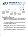
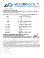
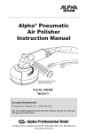
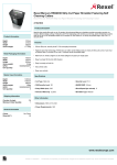
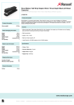
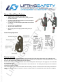
General Hook-Clamp Features:
•
Perpendicular or parallel release directions.
•
Safety Hitch pin lock for device locking safety, prevents
accidental dropping.
•
Computer generated parts precision-cut from aerospace
grade stainless steel plate.
•
Low friction, low effort lanyard-style release for maximum
user safety.
•
On Load / Off Load Releasing.
•
All parts 100% stainless steel.
•
No springs (apart from spring loaded safety hitch pin
option).
Hook-Clamp Operation
Device Locking
Having secured the recommended shackle to the rear end of the Hook-Clamp (anchorage / top suspension eye),
open the jaw by removing the hitch pin and lifting up the release lever and opening it to the released position. Insert
the pin of the shackle to be released into the jaw opening.
Secure the shackle by closing the release lever to the locked position and firmly lock the toggle pin over centre with
a vice-grip-like snap.
The shackle is now held firmly locked even with no load on the device. The safety pin (Hitch pin) can be reinserted
to prevent inadvertent release.
The Hook-Clamp is now ready to be loaded. Once the safety / hitch pin is removed, the Hook-Clamp is armed and
ready to be released. Either to “set down” a load or to drop a load in a controlled manor (as a drop test / dropping
clamp)
Device Releasing
Manual release of the loaded Hook-Clamp is activated by first removing the safety / hitch pin. This is done either
manually (directly by hand) or by a pull cord attached to the spring loaded safety hitch pin; ie, remotely and safety
from a distance. The safety hitch pin release cord can be activated from any direction.
Once the safety hitch pin has been removed the clamp is “loaded” or “Live” and pulling the cord attached to the
release lever WILL DROP / RELEASE the load. Pulling firmly on a release line connected to the end of the release
lever also means that the operator can safety release the load away from the “danger area”. The release line can
be activated “Directly” in any direction within the 90 degrees perpendicular and parallel to the line of load. The
“Standard” release lever can also be operated from above the load as shown in the diagram below with the use of a
suitable pulley; effectively giving 180 degree operation.
The Hook-Clamp can release the load with or without load on the unit. (providing the safety hitch pin is removed).
The use of the hitch pin is not required to secure the device in the locked position. It is an added, secondary safety
measure preventing inadvertent release. A safety hitch pin is provided with each unit. The standard safety hitch pin
is not spring loaded for remote operation (from distance by a pull cord).
Standard Lever
Reverse-Lever
Standard Lever with Pulley
Alternative Methods of Release
These are the alternative methods for releasing the shackle:
• Manually, pulling a long release line. No modification of the device is required. This method is mainly used
with lower capacity models, offers the lowest cost, and has many satisfied users.
• By winch line, using a winch and cable, such as used with a deck-mounted crane, to apply a load pulling
•
•
•
•
•
against the release lever. No modification of the device is required for this method.
Hydraulically, paying out the load against a fixed-length, bulkhead-mounted release cable. Using a clevis
instead of a shackle, a bulkhead-mounted hydraulic ram is attached to the rear end of the horizontally
positioned devise to pull it back after the unit is locked. The release cable is then secured to the bulkhead
and when release is desired, the hydraulic ram is actuated, allowing the Remote load release device to
move toward the load and eventually against the secured release cable and the load releases the unit. This
method allows the instalment of a pressure gauge into the hydraulic system to determine the actual tensile
load being released. No modification of the device is required
Explosive electric squib thrusters inserted into a special chamber below the toggle pin are used
successfully to activate the device.
Hydraulic pressure to drive a hydraulic cylinder to actuate the release lever of the Remote load release
device is being used with the device ram models. These units can be activated by hydraulic hand pump,
air-hydraulic foot pump, or electric pump.
Air Cylinders / Pneumatics / compresses air provide another method of release and are fitted for activation
using shop air at 60 to 100 PSI. The Pneumatic cylinder pushes the release lever activating the HookClamp
to release the load.
Radio remote control. Using a low voltage actuator attached to the HookClamp to remotely activate the
release lever. The actuator is activated from a safe distance by radio remote control hand set. (This is a
development item and will be available in the near future)
Warnings
Before operating the Hook-Clamp device, please heed these warnings.
•
Improper use of the Hook-Clamp device may cause injury.
•
The safety hitch pin must be used to prevent inadvertent release.
•
On a fully loaded Hook-Clamp with the safety hitch-pin removed, do not use the release line as a tag line
(to steer the load) or put any tension on it until time to release. An additional tag line secured to the upper
shackle (as illustrated on page 3) and kept taught at all times is highly recommended to maintain a slack
release line and prevent load twisting.
•
Stay clear of all objects released under load.
•
Do not exceed load capacity of this device.
•
Choose the proper size Hook-Clamp so that it is not loaded with or releasing more than its rated load.
•
Do not side load the Hook-Clamp as it may cause loss of retainer rings and other parts or permanently
damage the device.
•
While in its loaded position, do not obstruct the Hook-Clamp so as to prevent its body being aligned straight
with the line of load. Misalignment may prevent the movable jaw from releasing the connected member
even with the device in the released position.
•
Do not mount the Hook-Clamp such that the mounting fixture damages the unit while in use. This could
cause loss of parts and unit malfunction.
Maintenance
•
Inspection of the Hook-Clamp device is advised after each use.
•
After use in or near sea water, a fresh water rinse of the Hook-Clamp is advised before the device is
stored.
•
Pivot pins may require periodic re-lubrication.
Load Release Effort
Estimated Effort To Release Load
Detailed below are the figures of the estimated effort required to release a load at full capacity. This effort can be
adjusted by following the instructions below
Safe Working Load
Estimated Effort To Pull Lanyard To Release Capacity Load
590kg
3.62kg (can be adjusted, see above)
1,507kg
8.61kg (can be adjusted, see above)
3,194kg
18.14kg (can be adjusted, see above)
4,342kg
39.91kg (can be adjusted, see above)
7,186kg
65.77kg (can be adjusted, see above)
12,776kg
117kg (can be adjusted, see above)
14,902kg
136.53kg (can be adjusted, see above)
22,770kg
208kg (can be adjusted, see above)
28,747kg
263kg (can be adjusted, see above)
42,975kg
393kg (can be adjusted, see above)
69,960kg
640kg (can be adjusted, see above)
(Can be adjusted)
Adjusting The Effort Required to Operate the Manual release lever
(Remote load release device Over-Centre Pressure Adjustment)
Ample material has been left at the tip of the movable jaw (see arrow) where the jaw and
body come in contact. This aids in holding the device securely over-centre in the locked
position even when no load is applied to the device. It also helps prevent inadvertent
release of the device.
Should the user require that the effort to lock the release lever of the device over-centre be reduced, a suggestion
is to locate the area where the surface of the jaw tip comes in contact with the body tip and lightly file or grind off
material in that area. It is important to test the effort frequently after some material has been removed so as to
prevent the removal of too much material.
Should the user require that the effort to lock the release lever of the device over-centre be increased, a suggestion
is to increase the thickness of the material between the two surfaces by applying a centre punch mark in the area
of the jaw where the surfaces meet. Should there still be insufficient material to ensure the positive locking integrity
of the device, the contact area of the jaw will need to be spot-welded. This welded material will then need to be
ground to the appropriate thickness.
Hook-Clamp Users Manual
Part N°
Recommended
Shackle Size
A
B
C
D
E
F
G
SWL
(kg)
Break
load
(kg)
Weight
(kg)
4193T22955
Keyring
--
--
9.52
44.4
--
4.76
31.75
NOT
RATED
0.36
4193T22956
1/4"
11.93
7.87
10.41
73.39
4.57
9.39
49.78
589
2,902
0.14
4193T22957
7/16"
19.05
12.7
17.52
114.3
6.35
13.97
79.5
1,451
7,529
0.58
4193T22958
5/8"
26.92
19.05
25.4
168.14
9.65
20.57 115.82
3,193
15,966
1.81
4193T22959
3/4"
31.75
22.09
30.22 195.07 10.92
23.62 140.46
4,336
21,708
2.85
4193T22960
1"
42.92
28.7
41.4
30.73 174.49
7,184
35,924
5.67
4193T22961
1-3/8"
57.15
38.1
53.84 334.01 19.05
41.4
232.41 12,700
63,502
14.5
4193T22962
1-1/2"
60.45
41.14
57.15 361.95 20.57
45.21 251.96 14,905
74,525
18.14
4193T22963
1-3/4"
73.15
50.8
69.85 446.02
25.4
54.86 310.13 22,770 113,851
31.2
4193T22964
2"
82.55
57.15
79.5
501.14 28.44
62.48 349.25 28,748 143,743
48.98
4193T22965
2-1/2"
104.9
69.85
98.55
612.9
34.79
76.45 426.97 42,973 214,866
89.35
4193T22966
3"
127
82.55 120.65 782.06 44.45
97.79 544.32 69,962 349,810
138.8
247.65 14.22
-SWL (capacity) is a ratio of 5:1 to Break load.
Products are constantly being improved. Designs, dimensions, capacities and weights are subject to variation.
Hook-Clamp S-Series Welded Release
(Manual release for horizontal use)
The S-Series is securely mounted to a stainless steel dish.
This stable base allows the unit to function dependably
above seine gear during purse seine welded release
applications. Low kick-back, quiet operation, and a safe hitch
pin securement are key elements for welded release
operations.
Hook-Clamp LS/LM-Series
(Manual release / large and extra large jaw)
This is a modified LS-series provided with a front jaw
enlarged to receive up to 3.4” fibre line such as a fibre
forerunner. Additional side plates at the jaw area help spread
the load and prevent line chafing. Useful applications include
tug/barge connections and emergency releasing at port
terminals.
Hook-Clamp HYDRA-Series
(Hydraulic Ram release with manual back-up)
This Hook-Clamp is fitted with a hydraulic cylinder mounted
below the device, This set-up can be used to replace a
hydraulic release shackle (or hydraulic shackle), Above the
cylinder is a plunger which penetrates through a hole in the
body below the toggle pin. When this hydraulic system is
activated, the cylinder pushes through the plunger and the
toggle pin forcing the Clamp to release the shackle (or other
rigging gear). The Hydraulic shackle release Hook-Clamp
range can be operated remotely by a single 1/4" hydraulic
hose. Can be operated by manual hand pump, remote
accumulator or power pack (HPU). Most commonly used for
subsea / offshore applications for hydraulic release of
shackles.
Hook-Clamp PNU-Series
(Pheumatic release with manual back-up)
The "PNU-Series" Hook-Clamp is fitted with a compressed
air cylinder (Pneumatic ram) and allows for air pressure to
release the load. The Air Cylinders operate at 60 to 100 PSI.
Hook-Clamp IB/IBT Series
(Explosive charge release with manual back-up)
The "IB/IBT Series" Hook-Clamps feature either a squib or
squib-fired thruster and are generally operated electrically
and remotely. The Squib/Thruster offers a safe, split second
release activation and the standard release lever is still
available for further use. Squib activation is less expensive
than the Thruster, however thrusters offer a greater reliability.
Product Disclaimer
The specifications information and performance of the products manufactured by Selby Engineering & Lifting Safety ltd. and featured in this
publication may be changed without notice. Since the use of this information and the conditions by which the products are used are beyond the
control of Selby Engineering & Lifting Safety ltd, it is the obligation of the owner and/or the equipment operator to carefully read and understand
the Hook-Clamp's User’s Manual and determine the correct and safe selection and settings and conditions of use of the equipment and
products. To the extent that the law permits, any liability which may be incurred as a result of the use or future use of a product manufactured or
sold by Selby Engineering & Lifting Safety ltd. is limited to the cost of repairing or replacing the failed product or component at the discretion of
Selby Engineering & Lifting Safety ltd, either within, or outside of warranty periods, and does not extend to any loss or damage which may be
caused as a consequence of misuse or failure of the equipment or products. Selby Engineering & Lifting Safety ltd, its owner(s), its
shareholder(s), or its agents shall not in any event be liable for economic loss of profits, indirect, special, bodily injuries or consequential
damages. By virtue of taking possession of any product manufactured by Selby Engineering & Lifting Safety ltd., the owner and/or the
equipment operator agrees to the terms of this Disclaimer.