1
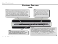
Table of Contents
Table of Contents
TABLE OF CONTENTS .................................................................................................2
PACKAGE CONTENTS......................................................................................................3
SYSTEM REQUIREMENTS ................................................................................................3
FEATURES ......................................................................................................................4
HARDWARE OVERVIEW ..................................................................................................5
Connections ..............................................................................................................5
LEDs.........................................................................................................................6
INSTALLATION .............................................................................................................7
ToS.......................................................................................................................... 33
Application ............................................................................................................. 34
User Define ............................................................................................................ 35
OUTBOUND FILTER ...................................................................................................... 36
INBOUND FILTER .......................................................................................................... 37
DNS SETUP ................................................................................................................. 38
FIREWALL & DMZ....................................................................................................... 40
ADVANCED ADSL ....................................................................................................... 41
ADVANCED LAN.......................................................................................................... 42
SNMP SETUP ............................................................................................................... 43
REMOTE MANAGEMENT .............................................................................................. 44
BEFORE YOU BEGIN .......................................................................................................7
INSTALLATION NOTES ....................................................................................................7
DEVICE INSTALLATION ................................................................................................. 11
Power on Router.....................................................................................................12
Factory Reset Button ..............................................................................................12
Network Connections..............................................................................................13
MAINTENANCE........................................................................................................... 45
SETUP.............................................................................................................................14
STATUS .......................................................................................................................... 50
Web-based Configuration Utility ............................................................................14
QUICK SETUP ...............................................................................................................15
ADSL SETUP ...............................................................................................................21
PPPoE/PPPoA .......................................................................................................22
Dynamic IP Address ...............................................................................................23
Static IP Address.....................................................................................................24
Bridge Mode ...........................................................................................................25
LAN SETUP .................................................................................................................26
Use the Router for DHCP.......................................................................................27
Disable the DHCP Server.......................................................................................27
Add Static DHCP....................................................................................................27
TIME AND DATE ...........................................................................................................28
PARENTAL CONTROL ....................................................................................................29
DEVICE INFO ................................................................................................................ 50
CONNECTED CLIENTS .................................................................................................. 51
STATISTICS ................................................................................................................... 52
ROUTING INFO ............................................................................................................. 53
PASSWORD ................................................................................................................... 45
SAVE/RESTORE SETTINGS ............................................................................................ 46
FIRMWARE UPDATE ...................................................................................................... 47
DIAGNOSTICS ............................................................................................................... 48
SYSTEM LOG ................................................................................................................ 49
HELP .............................................................................................................................. 54
TROUBLESHOOTING ................................................................................................ 55
NETWORKING BASICS ............................................................................................. 57
CHECK YOUR IP ADDRESS ........................................................................................... 57
STATICALLY ASSIGN AN IP ADDRESS ........................................................................... 58
TECHNICAL SPECIFICATIONS ............................................................................... 59
ADVANCED ...................................................................................................................30
PORT FORWARDING ......................................................................................................30
APPLICATION RULES ....................................................................................................31
QOS SETUP ..................................................................................................................32
D-Link DSL-2543B User Manual
2
Section 1 - Product Overview
•
•
•
•
•
•
Package Contents
DSL-2543B ADSL Router
Power Adapter
CD-ROM with User Manual
One twisted-pair telephone cable used for ADSL connection
One straight-through Ethernet cable
One Quick Installation Guide
Note: Using a power supply with a different voltage rating than the one included
with the DSL-2543B will cause damage and void the warranty for this product.
•
•
•
System Requirements
ADSL Internet service
Computer with:
• 200MHz Processor
• 64MB Memory
• CD-ROM Drive
• Ethernet Adapter with TCP/IP Protocol Installed
• Internet Explorer v6 or later, FireFox v1.5, or Safari 1.3 or above
• Windows 2000/XP/Vista
D-Link Click'n Connect Utility
D-Link DSL-2543B User Manual
3
Section 1 - Product Overview
11
•
•
•
•
•
•
•
•
•
•
•
•
•
Features
PPP (Point-to-Point Protocol) Security – The Router supports PAP (Password Authentication Protocol) and CHAP (Challenge Handshake
Authentication Protocol) for PPP connections. The Router also supports MSCHAP.
DHCP Support – Dynamic Host Configuration Protocol automatically and dynamically assigns all LAN IP settings to each host on your network. This
eliminates the need to reconfigure every host whenever changes in network topology occur.
Network Address Translation (NAT) – For small office environments, the Router allows multiple users on the LAN to access the Internet concurrently
through a single Internet account. This provides Internet access to everyone in the office for the price of a single user. NAT improves network security in
effect by hiding the private network behind one global and visible IP address. NAT address mapping can also be used to link two IP domains via a
LAN-to-LAN connection.
TCP/IP (Transfer Control Protocol/Internet Protocol) – The Router supports TCP/IP protocol, the language used for the Internet. It is compatible with
access servers manufactured by major vendors.
RIP-1/RIP-2 – The Router supports both RIP-1 and RIP-2 exchanges with other routers. Using both versions lets the Router to communicate with all RIP
enabled devices.
Static Routing – This allows you to select a data path to a particular network destination that will remain in the routing table and never “age out”. If you
wish to define a specific route that will always be used for data traffic from your LAN to a specific destination within your LAN (for example to another
router or a server) or outside your network (to an ISP defined default gateway for instance).
Default Routing – This allows you to choose a default path for incoming data packets for which the destination address is unknown. This is particularly
useful when/if the Router functions as the sole connection to the Internet.
ATM (Asynchronous Transfer Mode) – The Router supports Bridged Ethernet over ATM (RFC1483), IP over ATM (RFC1577), and PPP over ATM
(RFC 2364).
Precise ATM Traffic Shaping – Traffic shaping is a method of controlling the flow rate of ATM data cells. This function helps to establish the Quality of
Service for ATM data transfer.
High Performance – Very high rates of data transfer are possible with the Router. Up to 8 Mbps downstream bit rate using the G.dmt standard.
Full Network Management – The Router incorporates SNMP (Simple Network Management Protocol) support for web-based management and
text-based network management via an RS-232 or Telnet connection.
Telnet Connection – The Telnet enables a network manager to access the Router’s management software remotely.
Easy Installation – The Router uses a web-based graphical user interface program for convenient management access and easy set up. Any common web
browser software can be used to manage the Router.
D-Link DSL-2543B User Manual
4
Section 1 - Product Overview
•
Hardware Overview
Connections
ADSL Port
Use the ADSL cable to connect
to the your telephone line (RJ-11
port).
Ethernet Ports
Use the Ethernet ports to
connect the Router to a computer
or an Ethernet LAN.
D-Link DSL-2543B User Manual
Reset Button
To manually reset, depress
button with the power on for at
least seven seconds.
Power Button
Push in to power-on the Router.
Push again to power-off the
Router.
Power Insert
Use the adapter shipped with the
Router to connect to power
source.
5
Section 1 - Product Overview
Hardware Overview
LEDs
Power
A steady green light indicates the unit is powered on.
When the device is powered off this remains dark. Lights
steady green during power on self-test (POST). Once the
connection status has been settled, the light will blink
green. If the indicator lights steady green after the POST,
the system has failed and the device should be rebooted.
LAN
A solid green light indicates a valid link on
startup. This light will blink when there is activity
currently passing through the Ethernet port.
D-Link DSL-2543B User Manual
DSL
A steady green light indicates a valid
ADSL connection. This will light after
the ADSL negotiation process has
been settled. A blinking green light
indicates that ADLS is attempting to
sync.
Internet
A solid green light indicates the WAN IP address from IPCP or
DHCP and DSL is up or a static IP address is configured and
PPP negotiation has been successfully completed. If the
indicator blinks green, this means the Router is active. If the
Router power is off, this remains dark. A solid red light indicates
there is no DHCP response, no PPPoE response, PPPoE
authentication has failed, and/or there is no IP.
6
Section 2 – Installation
Installation
This section will walk you through the installation process. Placement of the Router is very important. Do not place the Router in an enclosed area
such as a closet, cabinet, or in the attic or garage.
Before You Begin
Please read and make sure you understand all the prerequisites for proper installation of your new Router. Have all the necessary information and
equipment on hand before beginning the installation.
Installation Notes
In order to establish a connection to the Internet it will be necessary to provide information to the Router that will be stored in its memory. For some
users, only their account information (Username and Password) is required. For others, various parameters that control and define the Internet
connection will be required. You can print out the two pages below and use the tables to list this information. This way you have a hard copy of all
the information needed to setup the Router. If it is necessary to reconfigure the device, all the necessary information can be easily accessed. Be
sure to keep this information safe and private.
Low Pass Filters
Since ADSL and telephone services share the same copper wiring to carry their respective signals, a filtering mechanism may be necessary to
avoid mutual interference. A low pass filter device can be installed for each telephone that shares the line with the ADSL line. These filters are easy
to install passive devices that connect to the ADSL device and/or telephone using standard telephone cable. Ask your service provider for more
information about the use of low pass filters with your installation.
Operating Systems
The DSL-2543B uses an HTML-based web interface for setup and management. The Web configuration manager may be accessed using any
operating system capable of running web browser software, including Windows 98 SE, Windows ME, Windows 2000, Windows XP, and Windows
Vista.
D-Link DSL-2543B User Manual
7
Section 2 – Installation
Web Browser
Any common Web browser can be used to configure the Router using the Web configuration management software. The program is designed to
work best with more recently released browsers such as Opera, Microsoft Internet Explorer® version 6.0, Netscape Navigator® version 6.2.3, or
later versions. The Web browser must have JavaScript enabled. JavaScript is enabled by default on many browsers. Make sure JavaScript has not
been disabled by other software (such as virus protection or web user security packages) that may be running on your computer.
Ethernet Port (NIC Adapter)
Any computer that uses the Router must be able to connect to it through the Ethernet port on the Router. This connection is an Ethernet connection
and therefore requires that your computer be equipped with an Ethernet port as well. Most notebook computers are now sold with an Ethernet port
already installed. Likewise, most fully assembled desktop computers come with an Ethernet NIC adapter as standard equipment. If your computer
does not have an Ethernet port, you must install an Ethernet NIC adapter before you can use the Router. If you must install an adapter, follow the
installation instructions that come with the Ethernet NIC adapter.
Additional Software
It may be necessary to install software on your computer that enables the computer to access the Internet. Additional software must be installed if
you are using the device a simple bridge. For a bridged connection, the information needed to make and maintain the Internet connection is stored
on another computer or gateway device, not in the Router itself.
If your ADSL service is delivered through a PPPoE or PPPoA connection, the information needed to establish and maintain the Internet connection
can be stored in the Router. In this case, it is not necessary to install software on your computer. It may however be necessary to change some
settings in the device, including account information used to identify and verify the connection.
All connections to the Internet require a unique global IP address. For bridged connections, the global IP settings must reside in a TCP/IP enabled
device on the LAN side of the bridge, such as a PC, a server, a gateway device such as a router or similar firewall hardware. The IP address can be
assigned in a number of ways. Your network service provider will give you instructions about any additional connection software or NIC
configuration that may be required.
D-Link DSL-2543B User Manual
8
Section 2 – Installation
Information you will need from your ADSL service
provider
Username
This is the Username used to log on to your ADSL service provider’s network. Your ADSL service provider uses this to identify your account.
Password
This is the Password used, in conjunction with the Username above, to log on to your ADSL service provider’s network. This is used to verify the
identity of your account.
WAN Setting / Connection Type
These settings describe the method your ADSL service provider uses to transport data between the Internet and your computer. Most users will use
the default settings. You may need to specify one of the following WAN Setting and Connection Type configurations (Connection Type settings listed
in parenthesis):
• PPPoE/PPoA (PPPoE LLC, PPPoE VC-Mux, PPPoA LLC, or PPPoA VC-Mux)
• Dynamic IP Address (1483 Bridged IP LLC or 1483 Bridged IP VC-Mux)
• Static IP Address (Bridged IP LLC, 1483 Bridged IP VC Mux, 1483 Routed IP LLC, 1483 Routed IP VC-Mux)
• Bridge Mode (1483 Bridged IP LLC or 1483 Bridged IP VC Mux)
Modulation Type
ADSL uses various standardized modulation techniques to transmit data over the allotted signal frequencies. Some users may need to change the
type of modulation used for their service. The default DSL modulation (Autosense) used for the Router automatically detects all types of ADSL,
ADSL2, and ADSL2+ modulation.
Security Protocol
This is the method your ADSL service provider will use to verify your Username and Password when you log on to their network. Your Router
supports the PAP and CHAP protocols.
D-Link DSL-2543B User Manual
9
Section 2 – Installation
VPI
Most users will not be required to change this setting. The Virtual Path Identifier (VPI) is used in conjunction with the Virtual Channel Identifier (VCI)
to identify the data path between your ADSL service provider’s network and your computer. If you are setting up the Router for multiple virtual
connections, you will need to configure the VPI and VCI as instructed by your ADSL service provider for the additional connections. This setting can
be changed in the WAN Settings window of the web management interface.
VCI
Most users will not be required to change this setting. The Virtual Channel Identifier (VCI) used in conjunction with the VPI to identify the data path
between your ADSL service provider’s network and your computer. If you are setting up the Router for multiple virtual connections, you will need to
configure the VPI and VCI as instructed by your ADSL service provider for the additional connections. This setting can be changed in the WAN
Settings window of the web management interface.
Information you will need about DSL-2543B
Username
This is the Username needed access the Router’s management interface. When you attempt to connect to the device through a web browser you
will be prompted to enter this Username. The default Username for the Router is “admin.” The user cannot change this.
Password
This is the Password you will be prompted to enter when you access the Router’s management interface. The default Password is “admin.” The
user may change this.
LAN IP addresses for the DSL-2543B
This is the IP address you will enter into the Address field of your web browser to access the Router’s configuration graphical user interface (GUI)
using a web browser. The default IP address is 192.168.1.1. This may be changed to suit any IP address scheme the user desires. This address will
be the base IP address used for DHCP service on the LAN when DHCP is enabled.
LAN Subnet Mask for the DSL-2543B
This is the subnet mask used by the DSL-2543B, and will be used throughout your LAN. The default subnet mask is 255.255.255.0. This can be
changed later.
D-Link DSL-2543B User Manual
10
Section 2 – Installation
Information you will need about your LAN or computer
:
Ethernet NIC
If your computer has an Ethernet NIC, you can connect the DSL-2543B to this Ethernet port using an Ethernet cable. You can also use the Ethernet
ports on the DSL-2543B to connect to other computer or Ethernet devices.
DHCP Client status
Your DSL-2543B ADSL Router is configured, by default, to be a DHCP server. This means that it can assign an IP address, subnet mask, and a
default gateway address to computers on your LAN. The default range of IP addresses the DSL-2543B will assign are from 192.168.1.2 to
192.168.1.254. Your computer (or computers) needs to be configured to obtain an IP address automatically (that is, they need to be configured as
DHCP clients.)
It is recommended that your collect and record this information here, or in some other secure place, in case you have to re-configure your ADSL
connection in the future.
Once you have the above information, you are ready to setup and configure your DSL-2543B ADSL Router.
Device Installation
The DSL-2543B connects two separate physical interfaces, an ADSL (WAN) and an Ethernet (LAN) interface. Place the Router in a location where
it can be connected to the various devices as well as to a power source. The Router should not be located where it will be exposed to moisture or
excessive heat. Make sure the cables and power cord are placed safely out of the way so they do not create a tripping hazard. As with any electrical
appliance, observe common sense safety procedures.
The Router can be placed on a shelf or desktop, ideally you should be able to see the LED indicators on the front if you need to view them for
troubleshooting.
D-Link DSL-2543B User Manual
11
Section 2 – Installation
Power on Router
The Router must be used with the power adapter included with the device.
1. Insert the AC Power Adapter cord into the power receptacle located on the rear panel of the Router and plug the adapter into a suitable nearby
power source.
2. Depress the Power button into the on position. You should see the Power LED indicator light up and remain lit. The Status LED should light solid
green and begin to blink after a few seconds.
3. If the Ethernet port is connected to a working device, check the Ethernet Link/Act LED indicators to make sure the connection is valid. The
Router will attempt to establish the ADSL connection, if the ADSL line is connected and the Router is properly configured this should light up
after several seconds. If this is the first time installing the device, some settings may need to be changed before the Router can establish a
connection.
Factory Reset Button
The Router may be reset to the original factory default settings by using a ballpoint or paperclip to gently push down the reset button in the following
sequence:
1. Press and hold the reset button while the device is powered off.
2. Turn on the power.
3. Wait for 5~8 seconds and then release the reset button.
Remember that this will wipe out any settings stored in flash memory including user account information and LAN IP settings. The device settings
will be restored to the factory default IP address 192.168.1.1 and the subnet mask is 255.255.255.0, the default management Username is “admin”
and the default Password is “admin.”
D-Link DSL-2543B User Manual
12
Section 2 – Installation
Network Connections
Connect ADSL Line
Use the ADSL cable included with the Router to connect it to a telephone wall socket or receptacle. Plug one end of the cable into the ADSL port
(RJ-11 receptacle) on the rear panel of the Router and insert the other end into the RJ-11 wall socket. If you are using a low pass filter device, follow
the instructions included with the device or given to you by your service provider. The ADSL connection represents the WAN interface, the
connection to the Internet. It is the physical link to the service provider’s network backbone and ultimately to the Internet.
Connect Router to Ethernet
The Router may be connected to a single computer or Ethernet device through the 10BASE-TX Ethernet port on the rear panel. Any connection to
an Ethernet concentrating device such as a switch or hub must operate at a speed of 10/100 Mbps only. When connecting the Router to any
Ethernet device that is capable of operating at speeds higher than 10Mbps, be sure that the device has auto-negotiation (NWay) enabled for the
connecting port. Use standard twisted-pair cable with RJ-45 connectors. The RJ-45 port on the Router is a crossed port (MDI-X). Follow standard
Ethernet guidelines when deciding what type of cable to use to make this connection. When connecting the Router directly to a PC or server use a
normal straight-through cable. You should use a crossed cable when connecting the Router to a normal (MDI-X) port on a switch or hub. Use a
normal straight-through cable when connecting it to an uplink (MDI-II) port on a hub or switch. The rules governing Ethernet cable lengths apply to
the LAN to Router connection. Be sure that the cable connecting the LAN to the Router does not exceed 100 meters.
Hub or Switch to Router Connection
Connect the Router to an uplink port (MDI-II) on an Ethernet hub or switch with a straight-through cable. If you wish to reserve the uplink port on the
switch or hub for another device, connect to any on the other MDI-X ports (1x, 2x, etc.) with a crossed cable.
Computer to Router Connection
You can connect the Router directly to a 10/100BASE-TX Ethernet adapter card (NIC) installed on a PC using the Ethernet cable provided.
D-Link DSL-2543B User Manual
13
Section 3 – Configuration
Setup
This section will show you how to set up and configure your new D-Link Router using the Web-based configuration utility.
Web-based Configuration Utility
Connect to the Router
To configure the WAN connection used by the Router it is first necessary to communicate with the Router through its management interface, which
is HTML-based and can be accessed using a web browser. The easiest way to make sure your computer has the correct IP settings is to configure
it to use the DHCP server in the Router. The next section describes how to change the IP configuration for a computer running a Windows operating
system to be a DHCP client.
To access the configuration utility, open a web-browser such as Internet
Explorer and enter the IP address of the router (192.168.1.1).
Type “admin” for the User Name and “admin” in the Password field. If
you get a Page Cannot be Displayed error, please refer to the
Troubleshooting section for assistance.
D-Link DSL-2543B User Manual
14
Section 3 – Configuration
Quick Setup
This chapter is concerned with using your computer to configure the WAN connection. The following chapter describes the various windows used to
configure and monitor the Router including how to change IP settings and DHCP server setup.
QUICK SETUP
Click the Setup Wizard link in the middle of the top of the window of the
Router’s opening page to launch a series of setup windows.
Alternatively, you can tick the Manual Setup check box and click the
desired setting option radio button in the middle of the window. The
manual ADSL connection setup is described later in this manual.
D-Link DSL-2543B User Manual
15
Section 3 – Configuration
QUICK SETUP – OPENING WINDOW
The first window of the Setup Wizard lists the basic steps in the process.
These steps are as follows:
1. Change the Router password.
2. Configure the connection to the Internet.
3. Save the new configuration settings and reboot the system.
QUICK SETUP – CHANGE YOUR ROUTER PASSWORD
This window of the Setup Wizard is used to change the Router password.
D-Link recommends to help secure your network, the user change the
Current Password from the factory default “admin.” The New Password
should be between 1 and 16 alphanumeric characters. Once you have
filled out the fields in this window, including re-typing the new password in
the Confirm Password field, click the Next button to continue.
If you do not want to change the password, click the Skip button to
proceed to the next step.
D-Link DSL-2543B User Manual
16
Section 3 – Configuration
QUICK SETUP – SELECT THE INTERNET CONNECTION TYPE
Now use the drop-down menus to select the Country, ISP Provider, and
Connection Type used for the Internet connection, and enter VPI and VCI
values if applicable. Your ISP has given this information to you—any
information that is not required for your provider will automatically be
grayed out in this window and subsequent Quick Setup windows.
The Connection Type options are 1483 Bridged IP LLC, 1483 Bridged IP
VC-Mux, 1483 Routed IP LLC, 1483 Routed IP VC-Mux, PPPoE LLC,
PPPoE VC-Mux, PPPoA LLC, and PPPoA VC-Mux.
Click the Next button when you are finished to proceed to the next Setup
Wizard window.
QUICK SETUP – SELECT THE INTERNET CONNECTION TYPE
If the following Setup Wizard window appears, please select the
connection type used by your ISP and then click the Next button. Most
users, however, will be sent directly to a Setup Wizard window for their
specific Internet connection type based on the information entered in the
previous Setup Wizard window.
D-Link DSL-2543B User Manual
17
Section 3 – Configuration
QUICK SETUP – PPPOE/PPPOA CONFIGURATION
Type in the User Name and Password used to identify and verify your
account to the ISP. If you are instructed to change the VPI or VCI number,
type in the correct setting in the available entry fields. Most users will not
need to change these settings. The Internet connection cannot function if
these values are incorrect.
Some users may have to adjust the Connection Type from the drop-down
menu at the bottom of this Setup Wizard window. The available
connection and encapsulation types are PPPoE LLC, PPoE VC-Mux,
PPPoA LLC, and PPPoA VC-Mux.
Click Next to go to the last Setup Wizard window.
QUICK SETUP – DYNAMIC IP CONFIGURATION
If you are instructed to change the VPI or VCI numbers, type in the correct
setting in the available entry fields. The Internet connection cannot
function if these values are incorrect. Select the specific Connection Type
from the drop-down menu. The available connection and encapsulation
types are 1483 Bridged IPLLC and 1483 Bridged IP VC-Mux. You may
want to copy the MAC address of your Ethernet adapter to the Router.
Some ISPs record the unique MAC address of your computer’s Ethernet
adapter when you first access their network. This can prevent the Router
(which has a different MAC address) from being allowed access to the
ISPs network (and the Internet). To clone the MAC address of your
computer’s Ethernet adapter, click the Copy Your PC’s MAC Address
button. This will copy the information to a file used by the Router to
present to the ISP’s server used for DHCP.
Click Next to go to the last Setup Wizard window.
D-Link DSL-2543B User Manual
18
Section 3 – Configuration
QUICK SETUP – STATIC IP CONFIGURATION
Enter values for VPI, VCI, IP Address, Subnet Mask, Default Gateway IP
address, Preferred DNS Server IP address, and Alternate DNS Server IP
address as instructed by your ISP. The Internet connection cannot
function if these values are incorrect.
Select the specific Connection Type from the drop-down menu. The
available connection and encapsulation types are 1483 Bridged IP LLC,
1483 Bridged IP VC-Mux, 1483 Routed IP LLC, and 1483 Routed IP
VC-Mux.
Click Next to go to the last Setup Wizard window.
QUICK SETUP – BRIDGE MODE CONFIGURATION
If you are instructed to change the VPI or VCI numbers, type in the correct
setting in the available entry fields. The Internet connection cannot
function if these values are incorrect.
Select the specific Connection Type from the drop-down menu. The
available connection and encapsulation types are 1483 Bridged IP LLC
and 1483 Bridged IP VC-Mux.
Click Next to go to the last Setup Wizard window.
D-Link DSL-2543B User Manual
19
Section 3 – Configuration
QUICK SETUP – FINISH & RESTART CONFIRMATION
Finally you can confirm that the setup process is completed. If you are
satisfied that you have entered all the necessary information correctly,
click the Restart button to save the new configuration settings and restart
the Router. If you need to change settings from a previous window, click
the Back button.
QUICK SETUP – REBOOT CONFIRMATION DIALOG
Click the OK button to proceed with the Router reboot.
QUICK SETUP – REBOOT TIME INDICATOR
The following window opens to indicate the amount of time it will take to
reboot the Router.
QUICK SETUP – REBOOT CONFIRMATION DIALOG
Click OK to continue.
D-Link DSL-2543B User Manual
20
Section 3 – Configuration
ADSL Setup
To access the ADSL Setup window, simply login to the Router or click either ADSL Setup in the Setup directory or Setup on the tool bar at the top
of the Web manager window. Tick the Manual Setup check box located next to the Setup Wizard button to display the following window:
To configure the Router’s basic configuration settings without running the
Setup Wizard, you can access the windows used to configure ADSL
Setup, LAN Setup, Time and Date, and Parental Control settings directly
from the Setup directory.
To access the ADSL Setup windows for Manual ADSL Connection Setup
for PPPoE/PPPoA, Dynamic IP Address, Static IP Address, and Bridge
Mode, click on the ADSL Setup link button on the left side of the first
window that appears when you successfully access the web manager.
The Router also allows you to change the Web manager’s language
settings using the drop-down menu on the left side of the window. The
choices are: English, Spanish, French, Italian, and German.
Click the PPPoE/PPPoA radio button to access the first Manual ADSL
Connection Setup window:
D-Link DSL-2543B User Manual
21
Section 3 – Configuration
PPPoE/PPPoA
To configure a PPPoE or PPPoA type WAN connection, follow these
steps:
1. Type the Username and Password used for your ADSL account. A
typical User Name will be in the form “[email protected].” The
Password may be assigned to you by your ISP or you may have
selected it when you set up the account with your ISP. The Service
Name field is used for the name of your Internet Service Provider.
This is optional.
2. Choose the Connection Type from the drop-down menu. This
defines both the connection protocol and encapsulation method
used for your ADSL service. The available options are PPPoE LLC,
PPPoE VC-Mux, PPPoA LLC and PPPoA VC-Mux. If you have not
been provided specific information for the Connection Type setting,
leave the default setting.
3. Leave the MTU value at the default setting unless you have
specific reasons to change this.
4. Some users will want to set an Idle Time Out. This is an age-out
value, in minutes, before the Router times out.
5. If you are instructed to change the VPI or VCI values, type in the
values assigned for your account.
6. When you are satisfied that all the WAN settings are configured
correctly, click the Apply Settings button. This will save the
settings and reboot the Router to let your changes take effect.
7. Upon restarting, the Router should automatically establish the
WAN connection. If it does not, click the Connect button at the
bottom of this window.
D-Link DSL-2543B User Manual
22
Section 3 – Configuration
Dynamic IP Address
A Dynamic IP Address connection configures the Router to automatically
obtain its global IP address from a DHCP server on the ISP’s network.
The service provider assigns a global IP address from a pool of addresses
available to the service provider. Typically the IP address assigned has a
long lease time, so it will likely be the same address each time the Router
requests an IP address.
To configure a Dynamic IP Address WAN connection, follow these steps:
1. Choose the Connection Type from the drop-down menu. This
defines both the connection protocol and encapsulation method
used for your ADSL service. The available options are 1483
Bridged IP LLC and 1483 Bridged IP VC-Mux. If you have not been
provided specific information for the Connection Type setting, leave
the default setting.
2. Some ISPs record the unique MAC Address of your computer’s
Ethernet adapter when you first access their network. This can
prevent the Router (which has a different MAC address) from being
allowed access to the ISPs network (and the Internet). To clone the
MAC address of your computer’s Ethernet adapter, click the Copy
Your PC’s MAC Address button.
3. If you are instructed to change the VPI or VCI values, type in the
values assigned for your account.
4. When you are satisfied that all the WAN settings are configured
correctly, click the Apply Settings button. This will save the
settings and reboot the Router to let your changes take effect.
5. Upon restarting, the Router should automatically establish the
WAN connection. If it does not, click the Connect button at the
bottom of this window.
D-Link DSL-2543B User Manual
23
Section 3 – Configuration
Static IP Address
When the Router is configured to use Static IP Address assignment for the
WAN connection, you must manually assign a global IP Address, Subnet
Mask, and Default Gateway IP address used for the WAN connection.
.
To configure a Static IP Address WAN connection, follow these steps:
1. Change the IP Address, Subnet Mask, and Default Gateway as
instructed by your ISP. These are the global IP settings for the
WAN interface. This is the “visible” IP address of your account.
Your ISP should have provided these IP settings to you. If your ISP
also asks you to change DNS server IP addresses, enter the
Preferred DNS Server and Alternate DNS Server information
manually.
2. Choose the Connection Type from the drop-down menu. This
defines both the connection protocol and encapsulation method
used for your ADSL service. The available options are 1483
Bridged IP LLC, 1483 Bridged IP VC-Mux, 1483 Routed IP LLC,
and 1483 Routed IP VC-Mux. If you have not been provided
specific information for this setting, leave the default setting.
3. If you are instructed to change the VPI or VCI values, type in the
values assigned for your account.
4. When you are satisfied that all the WAN settings are configured
correctly, click the Apply Settings button. This will save the
settings and reboot the Router to let your changes take effect.
5. Upon restarting, the Router should automatically establish the
WAN connection. If it does not, click the Connect button at the
bottom of this window.
D-Link DSL-2543B User Manual
24
Section 3 – Configuration
Bridge Mode
For Bridged connections it will be necessary for most users to install
additional software on any computer that will use the Router for Internet
access. The additional software is used for the purpose of identifying and
verifying your account, and then granting Internet access to the computer
requesting the connection. The connection software requires the user to
enter the User Name and Password for the ISP account. This information
is stored on the computer, not in the Router.
.
To configure a Static IP Address WAN connection, follow these steps:
1. Choose the Connection Type from the drop-down menu. This
defines both the connection protocol and encapsulation method
used for your ADSL service. The available options are 1483
Bridged IP LLC and 1483 Bridged IP VC-Mux. If you have not been
provided specific information for this setting, leave the default
setting.
2. If you are instructed to change the VPI or VCI values, type in the
values assigned for your account.
3. When you are satisfied that all the WAN settings are configured
correctly, click the Apply Settings button. This will save the
settings and reboot the Router to let your changes take effect.
4. Upon restarting, the Router should automatically establish the
WAN connection. If it does not, click the Connect button at the
bottom of this window.
D-Link DSL-2543B User Manual
25
Section 3 – Configuration
LAN Setup
To access the LAN Setup window, click the LAN Setup button in the Setup directory.
You can configure the LAN IP address to suit your preference. Many users
will find it convenient to use the default settings together with DHCP
service to manage the IP settings for their private network. The IP address
of the Router is the base address used for DHCP. In order to use the
Router for DHCP on your LAN, the IP address pool used for DHCP must
be compatible with the IP address of the Router. The IP addresses
available in the DHCP IP address pool will change automatically if you
change the IP address of the Router. See the next section for information
on DHCP setup.
To change the LAN Router IP Address or Subnet Mask, type in the
desired values in the Router Settings section and click the Apply
Settings button. Your web browser should automatically be redirected to
the new IP address. You will be asked to login again to the Router’s web
manager.
The DHCP server is enabled by default for the Router’s Ethernet LAN
interface. DHCP service will supply IP settings to workstations configured
to automatically obtain IP settings that are connected to the Router though
the Ethernet port. When the Router is used for DHCP it becomes the
default gateway for DHCP client connected to it. Keep in mind that if you
change the IP address of the Router the range of IP addresses in the pool
used for DHCP on the LAN will also be changed. The IP address pool can
be up to 253 IP addresses.
There are two options for DHCP service:
• You can use the Router as a DHCP server for your LAN.
• You can disable DHCP service and manually configure IP settings
for workstations.
D-Link DSL-2543B User Manual
26
Section 3 – Configuration
You may also configure DNS settings when using the Router in DHCP mode (Advanced > DNS Setup). When “Obtain DNS server address
automatically“ is clicked under DNS Server Configuration on the DNS Setup window, the Router will automatically relay DNS settings to properly
configured DHCP clients. To manually enter DNS IP addresses, click the “Use the following DNS server addresses“ radio button and type in a
Preferred DNS Server and Alternate DNS Server in the fields provided. The manually configured DNS settings will be supplied to clients that are
configured to request them from the Router.
Follow the instructions below according to which of the above DHCP options you want to use. When you have configured DHCP as you want, click
the Apply Settings button to commit the new settings.
Use the Router for DHCP
To use the built-in DHCP server, tick the Enable DHCP Server check box in the DHCP Server Settings (Optional) section if it is not already selected.
The IP address pool settings can be adjusted. The DHCP IP Address Range starts with the lowest available IP address (default = 192.168.1.2). If
you change the IP address of the Router this will change automatically to be 1 more that the IP address of the Router. The DHCP IP Address Range
ends with the highest IP address number in the pool. Type in the DHCP Lease Time in the entry field provided. This is the amount of time in hours
that a workstation is allowed to reserve an IP address in the pool if the workstation is disconnected from the network or powered off.
Disable the DHCP Server
To disable DHCP, deselect the Enable DHCP Server check box in the DHCP Server Settings (Optional) section and click the Apply Settings button.
Choosing this option will gray out most of the setting options on this window and require that workstations on the local network be configured
manually or use another DHCP server to obtain IP settings.
If you configure IP settings manually, make sure to use IP addresses in the subnet of the Router. You will need to use the Router’s IP address as the
Default Gateway for the workstation in order to provide Internet access.
Add Static DHCP
To add a static DHCP entry to the Static DHCP List, tick the Enable check box in the Add Static DHCP (Optional) section, type in an IP Address,
either click the Copy Your PC’s MAC Address button or manually enter a MAC Address, enter a Computer Name if desired, and click the Save
button. Click Clear to reset the values in this section. To delete an entry from the Static DHCP List, tick the corresponding check box and then click
the Remove Selected button. To modify a Static DHCP List entry, click the corresponding Edit hyperlink and then enter the information in the
appropriate fields in the Add Static DHCP (Optional) section.
D-Link DSL-2543B User Manual
27
Section 3 – Configuration
Time and Date
To access the Time and Date window, click the Time and Date button in the Setup directory.
The Router provides a number of options to maintain current date and
time including NTP.
To configure system time on the Router, select the method used to
maintain time. The options available include Network Time Protocol
(default), using your computer’s system clock (deselect the Automatically
synchronize with Internet time servers check box and then click the Copy
Your Computer’s Time Settings button), or set the time and date
manually (deselect the Automatically synchronize with Internet time
servers check box and make the desired changes).
If you opt to use NTP, you must use the drop-down menu to select the
NTP server URL in the First NTP Time Server field. You may also want to
choose a Second NTP Time Server using the drop-down menu.
The Router also allows you to set the time zone you are in by using the
Time Zone drop-down menu. In addition, you can configure Daylight
Saving by ticking the Enable Daylight Saving check box and then using
the drop-down menus to configure the desired Daylight Saving Offset and
Daylight Saving starting and ending dates.
When you are finished, click the Apply Settings button to set the system
time and date information.
D-Link DSL-2543B User Manual
28
Section 3 – Configuration
Parental Control
To access the Parental Control window, click the Parental Control button in the Setup directory.
Use this window to deny access to specified websites and to set Internet
access time periods.
URL or Uniform Resource Locator is a specially formatted text string that
uniquely defines an Internet website. This window will allow users to block
computers on the LAN from accessing certain URLs. This may be
accomplished by simply entering the URL to be blocked in the Website
field.
To configure this window for URL blocking, enter the website’s address
into the Website field, use the radio buttons to click the desired Day(s),
either All Week or Select Day(s) (in which case you must tick the
checkboxes for the desired individual days of the week), select the
desired Start Time and End Time or tick the All Day – 24 hrs checkbox,
and then click the Block Website button. Configured URL blocking
entries are displayed in the table in the middle of the window. To remove a
Blocked URL entry in the table, tick the Remove check box and then click
the Remove Selected button. To modify a table entry, click the
corresponding Edit hyperlink, make the desired changes, and then click
the Block Website button.
This window also enables you to determine when Internet access is
granted by using the settings in the Internet Access Time Restrictions
section of this window. Configure Time and days of the week and then use
the drop-down menu to toggle the Allow/Deny setting for each time period.
Clicking the Apply Settings button will allow your setting to take effect.
D-Link DSL-2543B User Manual
29
Section 3 – Configuration
Advanced
This chapter include the more advanced features used for network management and security.
Port Forwarding
To access the Port Forwarding window, click the Port Forwarding button in the Advanced directory.
Port Forwarding is used to allow Internet users access to LAN services.
Click the Pre-defined rule radio button to select an existing rule or click
Custom rule to set up a rule as follows.
Enter a rule name in the Custom rule filed, enter an IP address in the
Private IP field, select a Protocol Type from the drop-down menu, enter a
range of ports in the Public Start Port and Public End Port fields, and then
click the Add/Apply Settings button to see the customized rule in the
ACTIVE PORT FORWARDING RULES table. Finally, click the Reboot
button on the left panel to let your changes take effect.
D-Link DSL-2543B User Manual
30
Section 3 – Configuration
Application Rules
To access the Application Rules window, click the Application Rules button in the Advanced directory.
Some applications require that the remote parties open specific ports in
the Router’s firewall for access. Port Trigger dynamically opens the Open
Ports in the firewall when an application on the LAN initiates a TCP/UDP
connection to a remote party using Trigger Ports. The Router allows the
remote party form the WAN side to establish new connections back to the
application on the LAN side using the Open Ports.
Applications such as games, video conferencing, and other remote
access applications require that specific ports in the Router’s firewall be
opened for access by applications.
You can configure the port settings on this window by clicking the “Select
an application“ radio button and then using the drop-down menu to
choose an existing application, or by clicking the “Custom
application“ radio button and entering your own Application Rule in the
field provided. Click Apply Settings when you are finished with the port
setting configuration. The new Application Rule will appear in the Active
Application Rules table at the bottom of the window.
D-Link DSL-2543B User Manual
31
Section 3 – Configuration
QoS Setup
.
To access the QoS Setup window, click the QoS Setup button in the Advanced directory.
QoS or Quality of Service allows your Router to help prioritize the data
packet flow in your Router and network. This is very important for time
sensitive applications such as VoIP where it may help prevent dropped
calls. Large amounts of non-critical data can be scaled so as not to affect
these prioritized sensitive real-time programs.
The Router allows you to either tick the Auto Detection check box to
automatically detect real-time streaming to prioritize entire packets
(default), or to manually configure IP QoS based on ToS, Application, and
User Define classifications. D-Link recommends you leave Auto Detection
enabled.
Selecting ToS in the Classify drop-down menu will display the following
window:
D-Link DSL-2543B User Manual
32
Section 3 – Configuration
ToS
From this window, you can use the Bandwidth drop-down menu to select
the desired value of bandwidth, in kbps, that will be divided up among the
four priority queues. Input a Weight, in percentage, and a Range from 0 to
7. Tick the Enable check box for each queue configured. Some
experimentation may be necessary to achieve the optimum results with
your particular ISP’s connection. When you are finished, click Apply
Settings and then click the Reboot button to let your new settings take
effect.
Selecting Application in the Classify drop-down menu will display the
following window:
D-Link DSL-2543B User Manual
33
Section 3 – Configuration
Application
On this window, you can select the mechanism by which the four priority
queues are emptied by assigning a Weight, in percentage terms, to each
priority queue, and then selecting the associated Application Type. Tick
the Enable check box for each queue configured. Some experimentation
may be necessary to achieve the optimum results with your particular
ISP’s connection. When you are finished, click Apply Settings and then
click the Reboot button to let your new settings take effect.
Selecting User Define in the Classify drop-down menu will display the
following window:
D-Link DSL-2543B User Manual
34
Section 3 – Configuration
User Define
On this window, you can assign a Weight, on a percentage basis, to each
of the four priority queues. In addition, you can specify the number of
bytes from the beginning of a given packet’s IP header to set a pointer.
From this pointer, you can then specify a Value (in hexadecimal) and a
Mask (in hexadecimal) for the Router to match when examining packets
crossing the specified priority queue. It is recommended that you not enter
a QoS scheme of this type unless you fully understand Offsets, pointers,
masks, and IP headers or you are instructed to do so by your ISP. When
you are finished, click Apply Settings and then click the Reboot button to
let your new settings take effect.
Here’s an example of some typical User Defined IP QoS values:
Packet
Value
Mask
IP Header Offset
IGMP
0x02
0xff
9
FTP
0x0015
0xffff
22 (destination port)
IP Source 192.168.1.1
0xc0a80101
0xffffffff
12
D-Link DSL-2543B User Manual
35
Section 3 – Configuration
Outbound Filter
To access the Outbound FIlter window, click the Outbound Filter button in the Advanced directory.
The Outbound Filter allows you to create a filter rule to block outgoing IP
traffic by specifying a filter name and at least one condition on this
window. All of the specified conditions in this filter rule must be satisfied
for the rule to take effect. Filters are used to allow or deny LAN or WAN
users from accessing the Internet or your internal network.
Click the Add/Apply button and then click the Reboot button on the left
panel to let your changes take effect.
Filters Parameter
Description
Name
Enter a name for the new filter.
Protocol
Select the transport protocol (TCP, UDP, ICMP, TCP/
UD, or Any) that will be used for the filter rule.
Source IP Address & Source
Subnet Mask
For an Outbound Filter, this is the IP address or IP
addresses and their associated subnets on your LAN
for which you are creating the filter rule. For an
Inbound Filter, this is the IP address or IP addresses
and their associated subnets for which you are
creating the filter rule.
Source Port
The Source Port is the TCP/UDP port on either the
LAN or WAN depending on if you are configuring an
Outbound or Inbound Filter rule.
Destination IP Address &
Destination Subnet Mask
Where the Destination IP address and subnet mask
resides also depends on if you are configuring an
Inbound or Outbound filter rule.
Destination Port
The Destination Port is the TCP/UDP port on either
the LAN or WAN depending on if you are configuring
an Outbound or Inbound Filter rule.
D-Link DSL-2543B User Manual
36
Section 3 – Configuration
Inbound Filter
To access the Inbound Filter window, click the Inbound Filter button in the Advanced directory.
The Inbound Filter allows you to create a filter rule to allow incoming IP
traffic by specifying a filter name and at least one condition on this
window. All of the specified conditions in this filter rule must be satisfied
for the rule to take effect. By default, all incoming IP traffic from the
Internet is blocked when the firewall is enabled.
Click the Add/Apply button and then click the Reboot button on the left
panel to let your changes take effect.
Filters Parameter
Description
Name
Enter a name for the new filter.
Protocol
Select the transport protocol (TCP, UDP, ICMP, TCP/
UD, or Any) that will be used for the filter rule.
Source IP Address & Source
Subnet Mask
For an Outbound Filter, this is the IP address or IP
addresses and their associated subnets on your LAN
for which you are creating the filter rule. For an
Inbound Filter, this is the IP address or IP addresses
and their associated subnets for which you are
creating the filter rule.
Source Port
The Source Port is the TCP/UDP port on either the
LAN or WAN depending on if you are configuring an
Outbound or Inbound Filter rule.
Destination IP Address &
Destination Subnet Mask
Where the Destination IP address and subnet mask
resides also depends on if you are configuring an
Inbound or Outbound filter rule.
Destination Port
The Destination Port is the TCP/UDP port on either
the LAN or WAN depending on if you are configuring
an Outbound or Inbound Filter rule.
D-Link DSL-2543B User Manual
37
Section 3 – Configuration
DNS Setup
To access the DNS Setup window, click the DNS Setup button in the Advanced directory.
The Router can be configured to relay DNS settings from your ISP or
another available service to workstations on your LAN. When using DNS
relay, the Router will accept DNS requests from hosts on the LAN and
forward them to the ISP’s, or alternative DNS servers. DNS relay can use
auto discovery or the DNS IP address can be manually entered by the
user. Alternatively, you may also disable the DNS relay and configure
hosts on your LAN to use DNS servers directly. Most users who are using
the Router for DHCP service on the LAN and are using DNS servers on
the ISP’s network, will leave DNS relay enabled (either auto discovery or
user configured).
If you have not been given specific DNS server IP addresses or if the
Router is not pre-configured with DNS server information, select the
“Obtain DNS server address automatically” option. Auto discovery DNS
instructs the Router to automatically obtain the DNS IP address from the
ISP through DHCP. If your WAN connection uses a Static IP address, auto
discovery for DNS cannot be used.
If you have DNS IP addresses provided by your ISP, click the “Use the
following DNS server addresses” radio button and enter these IP
addresses in the available entry fields for the Preferred DNS Server and
the Alternative DNS Server. When you have configured the DNS settings
as desired, click the Apply Settings button and then click the Reboot
button on the left panel to let your changes take effect.
The Router supports DDNS (Dynamic Domain Name Service). The
Dynamic DNS service allows a dynamic public IP address to be
associated with a static host name in any of the many domains, allowing
access to a specified host from various locations on the Internet. This is
enabled to allow remote access to a host by clicking a hyperlinked URL in
the form hostname.dyndns.org, Many ISPs assign public IP addresses
D-Link DSL-2543B User Manual
38
Section 3 – Configuration
using DHCP, this can make it difficult to locate a specific host on the LAN
using standard DNS. If for example you are running a public web server or
VPN server on your LAN, this ensures that the host can be located from
the Internet if the public IP address changes. DDNS requires that an
account be setup with one of the supported DDNS providers.
Tick the Enable Dynamic DNS check box, enter the required DDNS
information, click the Apply Settings button, and then click the Reboot
button on the left panel to let your changes take effect to set this
information in the Router.
D-Link DSL-2543B User Manual
Note
DDNS requires that an account be setup with one of the supported
DDNS servers prior to engaging it on the Router. This function will not
work without an accepted account with a DDNS server.
39
Section 3 – Configuration
Firewall & DMZ
To access the Firewall & DMZ window, click the Firewall & DMZ button in the Advanced directory.
Firewalls may conflict with certain interactive applications such as video
conferencing or playing Internet video games. For these applications, a
firewall bypass can be set up using a DMZ IP address. The DMZ IP
address is a “visible” address and does not benefit from the full protection
of the firewall function. Therefore it is advisable that other security
precautions be enabled to protect the other computers and devices on the
LAN. It may be wise to use isolate the device with the DMZ IP address
from the rest of the LAN.
If you want to use video conferencing, for example, and still use a firewall,
you can use the DMZ IP address function. In this case, you must have a
PC or server through which video conferencing will take place. The IP
address of this PC or server will then be the DMZ IP address. You can
designate the server’s IP address as the DMZ by going to the DMZ
Settings section and typing in the IP address in the IP Address field
provided and then enabling its status by ticking the Enable DMZ
checkbox, clicking Apply Settings, and then clicking the Reboot button
on the left panel to let your changes take effect.
For the system that uses the DMZ IP address, you may want to manually
assign an IP address to it and adjust your DHCP server addresses so that
the DMZ IP address is not included in the DHCP server range. This way
you avoid possible IP address problems if you reboot the DMZ system.
The Firewall Settings section allows the Router to enforce specific
predefined policies intended to protect against certain common types of
attacks. Stateful Packet Inspection (SPI) is a packet inspection process
that blocks unwanted and unrequested packets trying to reach PCs on
your LAN. A DoS "denial-of-service" attack is characterized by an explicit
attempt by attackers to prevent legitimate users of a service from using
D-Link DSL-2543B User Manual
40
Section 3 – Configuration
that service. Examples include: attempts to "flood" a network, thereby preventing legitimate network traffic, attempts to disrupt connections between
two machines, thereby preventing access to a service, attempts to prevent a particular individual from accessing a service, or, attempts to disrupt
service to a specific system or person. Port scan protection is designed to block attempts to discover vulnerable ports or services that might be
exploited in an attack from the WAN.
When you have selected the desired Firewall settings by ticking the corresponding check boxes for the various types of protection offered on this
window, click Apply Settings. Click the Reboot button on the left panel to let your changes take effect.
Advanced ADSL
To access the Advanced ADSL window, click the Advanced ADSL button in the Advanced directory.
This window allows the user to set the configuration for ADSL protocols.
For most ADSL accounts the default settings Autosense will work. This
configuration works with all ADSL implementations. If you have been
given instructions to change the Modulation method used, select the
desired option from the Modulation Type drop-down menu and click the
Apply Settings button. Click the Reboot button on the left panel to let
your changes take effect.
Leave the Capability setting at the bottom of the window unchanged
unless otherwise instructed by your ISP. Both Bitswap Enable and
Seemless Rate Adaption (SRA) Enable deal with tests that determine the
line condition between your Router and the ISP’s Central office.
D-Link DSL-2543B User Manual
41
Section 3 – Configuration
Advanced LAN
To access the Advanced LAN window, click the Advanced LAN button in the Advanced directory.
UPnP supports zero-configuration networking and automatic discovery for
many types of networked devices. When enabled, it allows other devices
that support UPnP to dynamically join a network, obtain an IP address,
convey its capabilities, and learn about the presence and capabilities of
other devices. DHCP and DNS service can also be used if available on
the network. UPnP also allows supported devices to leave a network
automatically without adverse effects to the device or other devices on the
network. UPnP is a protocol supported by diverse networking media
including Ethernet, Firewire, phone line, and power line networking.
To enable UPnP for any available connection, tick the Enable UPnP check
box, select the connection or connections on which you will enable UPnP
listed under Available Connections and click the Apply Settings button.
Click the Reboot button on the left panel to let your changes take effect.
When “Enable Multicast Streams (IGMP)” is ticked, Multicast packets are
allowed to pass in both directions on the WAN interface. Most users will
want to leave this on.
The Router supports RIP v1 and RIP v2 used to share routing tables with
other Layer 3 routing devices on your local network or remote LAN. The
Operation setting refers to the RIP request. Select Active to allow RIP
requests from other devices. Select Passive to instruct the Router to make
RIP requests for routing tables from other devices.
To enable RIP, select Enabled from the RIP pull-down menu, select the
Protocol (RIPv1, RIPv2, or RIP Both) and Operation (Active or Passive),
and click Apply Settings.
To define a gateway and hop to route data traffic, complete the fields in
the Add Static Route section and click Apply Settings.
D-Link DSL-2543B User Manual
42
Section 3 – Configuration
SNMP Setup
To access the SNMP Setup window, click the SNMP Setup button in the Advanced directory.
Simple Network Management Protocol is a standard for internetwork and
intranetwork management.
Tick the SNMP Agent check box and configure the parameters for SNMP
on this window and then click the Apply Settings button. Click the
Reboot button on the left panel to let your changes take effect.
D-Link DSL-2543B User Manual
43
Section 3 – Configuration
Remote Management
To access the Remote Management window, click the Remote Management button in the Advanced directory.
The Router allows remote Web and Telnet management in the top section
of the window. Tick the Enable Remote Management check box, enter an
IP address of the remote system used for management, enter optional
identifying information in the Details field if desired, and click the
Add/Apply button. Once the IP address appears in the bottom half of this
section, click the Reboot button on the left panel to let your changes take
effect.
Use the Access Control section in the middle of the window to restrict a
service from being accessed via the WAN interface. Click the Apply
Settings button and then click the Reboot button on the left panel to let
your changes take effect.
D-Link DSL-2543B User Manual
44
Section 3 – Configuration
Maintenance
The Maintenance directory features an array of options designed to help you get the most out of your Router.
Password
To access the Password window, click the Settings button in the Maintenance directory.
To change the Administrator’s password, type the Current Password in
the first field, the New Password in the second field, and enter the
password again in the Confirm Password field to be certain you have
typed it correctly. Click the Apply Settings button and then click the
Reboot button on the left panel to let your changes take effect. The
system User Name remains “admin,” this cannot be changed using the
Web manager interface.
D-Link DSL-2543B User Manual
45
Section 3 – Configuration
Save/Restore Settings
To access the Save/Restore Settings window, click the Save/Restore Settings button in the Maintenance directory.
Once you have configured the Router to your satisfaction, it is a good idea
to back up the configuration file to your computer. To save the current
configuration settings to your computer, click the Save button. You will be
prompted to select a location on your computer to put the file. The file type
is bin and may be named anything you wish.
To load a previously saved configuration file, click the Browse button and
locate the file on your computer. Click the Upload Settings button to load
the settings from your local hard drive. Confirm that you want to load the
file when prompted. The Router will reboot and begin operating with the
configuration settings that have just been loaded.
To reset the Router to its factory default settings, click the Restore Device
button. You will be prompted to confirm your decision to reset the Router.
The Router will reboot with the factory default settings including IP
settings (192.168.1.1) and Administrator password (admin).
D-Link DSL-2543B User Manual
46
Section 3 – Configuration
Firmware Update
To access the Firmware Update window, click the Firmware Update button in the Maintenance directory.
Use this window to load the latest firmware for the device. Note that the
device configuration settings may return to the factory default settings, so
make sure you save the configuration settings with the Save/Restore
Settings window described on the previous page.
To upgrade firmware, type in the name and path of the file or click on the
Browse button to search for the file. Click the Update Firmware button to
begin copying the file. The file will load and restart the Router
automatically.
To save your current configuration file to your computer, click the Backup
Now button. A File Download dialog box will open. Click the Save button
and then designate the location for the configuration file in the Save As
window that immediately opens. The default location is your desktop.
Note
Performing a Firmware Upgrade can sometimes change the
configuration settings. Be sure to backup the Router’s configuration
settings before upgrading the firmware.
D-Link DSL-2543B User Manual
47
Section 3 – Configuration
Diagnostics
To access the Diagnostic window, click the Diagnostics button in the Maintenance directory.
This window is used to test connectivity of the Router. A Ping test may be
done through the local or external interface to test connectivity to known IP
addresses. The diagnostics feature executes a series of tests of your
system software and hardware connections. Use this window when
working with your ISP to troubleshoot problems.
D-Link DSL-2543B User Manual
48
Section 3 – Configuration
System Log
To access the System Log window, click the System Log button in the Maintenance directory.
The system log allows you to configure local and remote logging, and to
view the logs that have been created.
To generate a system log, tick the Log check box. Select the Log Level
and Display Level from the pull-down menus. The levels available are the
same for each type of level: Emergency, Alert, Critical, Error, Warning,
Notice, Informational and Debugging. Use the Mode drop-down menu to
select Local, Remote, or Both. Click the Apply Settings button and then
click the Reboot button on the left panel to allow your new settings to
take effect.
The bottom half of this window allows you to configure the Router to
e-mail the system log to a specific e-mail address. To use this feature,
you will need to contact your ISP provider to obtain the appropriate e-mail
server information. Tick the Enable Email Notification check box, fill in the
various fields offered including the last three if you also want to enable
authentication (which requires the check box to be ticked).
D-Link DSL-2543B User Manual
49
Section 3 – Configuration
Status
Use the various read-only windows to view system information and monitor performance.
Device Info
To access the Device Info window, click the Device Info button in the Status directory.
Use this window to quickly view basic current information about the LAN
and WAN interfaces and device information including Firmware Version
and MAC address.
D-Link DSL-2543B User Manual
50
Section 3 – Configuration
Connected Clients
To access the Connected Clients window, click the Connected Clients button in the Status directory.
The Connected LAN Clients list displays active DHCP clients when the
router is acting as a DHCP server.
D-Link DSL-2543B User Manual
51
Section 3 – Configuration
Statistics
To access the Statistics window, click the Statistics button in the Status directory.
Use this window to monitor traffic on the Ethernet or ADSL connection.
This window also displays information concerning ADSL status.
D-Link DSL-2543B User Manual
52
Section 3 – Configuration
Routing Info
To access the Routing Info window, click the Routing Info button in the Status directory.
This window is used to direct forwarding by matching destination
addresses to the network paths used to reach them.
Click the Refresh button to refresh the Routing Table information.
D-Link DSL-2543B User Manual
53
Section 3 – Configuration
Help
To access the Help window, click the Help directory.
D-Link DSL-2543B User Manual
54
Appendix A – Troubleshooting
Troubleshooting
This chapter provides solutions to problems that might occur during the installation and operation of the DSL-2543B. Read the following
descriptions if you are having problems. (The examples below are illustrated in Windows® XP. If you have a different operating system, the
screenshots on your computer will look similar to the following examples.)
1.
How do I configure my DSL-2543B Router without the CD-ROM?
•
•
•
•
Note:
2.
Please refer to the next section “Networking Basics” to check your PC’s IP configuration if you can’t see the login windows.
How do I reset my Router to the factory default settings?
•
•
•
Note:
3.
Connect your PC to the Router using an Ethernet cable.
Open a web browser and enter the address http://192.168.1.1
The default username is ‘admin’ and the default password is ‘admin’.
If you have changed the password and cannot remember it, you will need to reset the Router to the factory default setting (see question 2),
which will set the password back to ‘admin’.
Ensure the Router is powered on.
Press and hold the reset button on the back of the device for approximately 5 to 8 seconds.
This process should take around 1 to 2 minutes.
Resetting the Router to the factory default settings will erase the current configuration settings. To reconfigure your settings, login to the Router as
outlined in question 1, then run the Quick Setup wizard.
What can I do if my Router is not working correctly?
There are a few quick steps you can take to try and resolve any issues:
• Follow the directions in Question 2 to reset the Router.
• Check that all the cables are firmly connected at both ends.
• Check the LEDs on the front of the Router. The Power indicator should be on, the Status indicator should flash, and the DSL and LAN
indicators should be on as well.
D-Link DSL-2543B User Manual
55
Appendix A – Troubleshooting
•
4.
Please ensure that the settings in the Web-based configuration manager, e.g. ISP username and password, are the same as the settings
that have been provided by your ISP.
Why can’t I get an Internet connection?
For ADSL ISP users, please contact your ISP to make sure the service has been enabled/connected by your ISP and that your ISP username and
password are correct.
5.
What can I do if my Router can’t be detected by running the installation CD?
•
•
•
•
Note:
Ensure the Router is powered on.
Check that all the cables are firmly connected at both ends and all LEDs work correctly.
Ensure only one network interface card on your PC is activated.
Click on Start > Control Panel > Security Center to disable the firewall.
There is a potential security issue if the firewall is disabled on your PC. Please remember to turn it back on once you have finished the whole
installation procedure. This will enable you to be able to surf the Internet without any problem.
D-Link DSL-2543B User Manual
56
Appendix B - Networking Basics
Networking Basics
Check Your IP Address
After you install your new D-Link adapter, by default, the TCP/IP settings should be set to obtain an IP address from a DHCP server (i.e. wireless
router) automatically. To verify your IP address, please follow the steps below.
Click on Start > Run. In the run box type cmd and click on the OK.
At the prompt, type ipconfig and press Enter.
This will display the IP address, subnet mask, and the default
gateway of your adapter.
If the address is 0.0.0.0, check your adapter installation, security
settings, and the settings on your router. Some firewall software
programs may block a DHCP request on newly installed adapters.
If you are connecting to a wireless network at a hotspot (e.g. hotel,
coffee shop, airport), please contact an employee or administrator
to verify their wireless network settings.
D-Link DSL-2543B User Manual
57
Appendix B - Networking Basics
Statically Assign An IP Address
If you are not using a DHCP capable gateway/router, or you need to assign a static IP address, please follow the steps below:
Step 1
Windows® XP - Click on Start > Control Panel > Network Connections.
Windows® 2000 - From the desktop, right-click on the My Network Places > Properties.
Step 2
Right-click on the Local Area Connection which represents your D-Link network adapter and select Properties.
Step 3
Highlight Internet Protocol (TCP/IP) and click on the Properties.
Step 4
Click on the Use the following IP address and enter an IP address that is on the same subnet as
your network or the LAN IP address on your router.
Example: If the router’s LAN IP address is 192.168.1.1, make your IP address 192.168.1.X where X
is a number between 2 and 99. Make sure that the number you choose is not in use on the network.
Set Default Gateway the same as the LAN IP address of your router (192.168.1.1).
Set Primary DNS the same as the LAN IP address of your router (192.168.1.1). The Secondary
DNS is not needed or you may enter a DNS server from your ISP.
Step 5
Click on the OK twice to save your settings.
D-Link DSL-2543B User Manual
58
Appendix C – Technical Specifications
Technical Specifications
Data Transfer Rate
ADSL Standards
•
•
•
•
ANSI T1.413 Issue 2
ITU G.992.1 (G.dmt) Annex B
ITU G.992.2 (G.lite) Annex B
• ITU G.994.1 (G.hs)
•
•
ADSL2 Standards
•
ITU G.992.3 (G.dmt.bis) Annex B
•
ADSL2+ Standards
•
ITU G.992.5 Annex B
Protocols
•
•
•
•
•
•
•
•
•
•
IEEE 802.1d Spanning
Tree
TCP/UDP
ARP
RARP
ICMP
RFC1058 RIP v1
RFC1213 SNMP v1 & v2c
RFC1334 PAP
RFC1389 RIP v2
RFC1577 Classical IP over
ATM
D-Link DSL-2543B User Manual
•
•
•
•
•
•
RFC1483/2684
Multiprotocol
Encapsulation over ATM
Adaptation Layer 5 (AAL5)
RFC1661 Point to Point
Protocol
RFC1994 CHAP
RFC2131 DHCP Client /
DHCP Server
RFC2364 PPP over ATM
RFC2516 PPP over
Ethernet
G.dmt full rate downstream: up to 8 Mbps / upstream: up to 1
Mbps
G.lite: ADSL downstream up to 1.5 Mbps / upstream up to 512
Kbps
G.dmt.bis full rate downstream: up to 12 Mbps / upstream: up
to 1 Mbps
ADSL full rate downstream: up to 24 Mbps / upstream: up to 1
Mbps
Media Interface
•
•
ADSL interface: RJ-11 connector for connection to 24/26
AWG twisted pair telephone line
LAN interface: four RJ-45 ports for 10/100BASE-T Ethernet
connection
59