1
Chapter 2
User-Programmable Functions
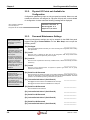
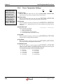
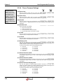
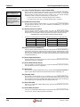
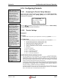
{L1} Linear Thermal Expansion Coeff of Switch Rod
INFO - Characters in ’{ }’
refer to password levels.
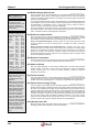
TIP - Use the blank lines
provided next to each
configuration option to write
down the corresponding
settings you entered in the
flow computer.
_______________
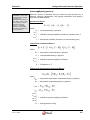
This entry applies to unidirectional compact provers only (except Brooks SVP see following
setting). Enter the squared coefficient of thermal expansion for any switch rod components
which may affect the water draw volume of the compact prover. This Thermal Expansion
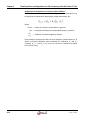
Coefficient is used to calculate the CTSP factor for the compact prover:
For US Units: Carbon Steel = 0.0000124; Stainless Steel = 0.0000177.
For Metric Units: Carbon Steel = 0.0000223; Stainless Steel = 0.0000319.
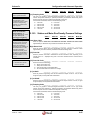
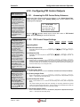
{L1} Coefficient of Invar Rod
_______________
This entry applies to Brooks Compact Provers only. This prover uses an invar rod to separate
the optical detector switches. The rod has a coefficient of 0.0000008 per F (US units) or
0.0000014 per C (metric units).
{L1} Plenum Pressure Constant
_______________
This entry applies to Brooks Compact Provers only. Enter the Nitrogen Spring Plenum
Pressure Constant used to calculate the plenum pressure needed to operate the Brooks
Compact Prover. This pressure is related to the prover line pressure at the time of proving:
Plenum Pressure = (Line Pressure / Plenum Constant) + 60 Psig
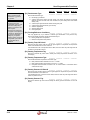
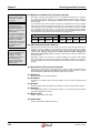
The plenum constant depends on the size of the Brooks Compact Prover. Valid values are:
SIZE
PLENUM CONSTANT
SIZE
PLENUM CONSTANT
8-inch
3.50
18-inch
5.00
12-inch Mini
3.20
24-inch
5.88
12-inch Standard
3.20
Larger
Refer to Brooks
{L2} Plenum Pressure Deadband %
_______________
This entry applies to Brooks Compact Provers only. Enter the Plenum Pressure Deadband %.
The Brooks Compact Prover requires that the plenum pressure be maintained within certain
limits. The flow computer calculates the correct plenum pressure at the beginning of each
prove sequence and will charge or vent nitrogen until the measured plenum pressure is within
the specified deadband %.
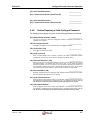
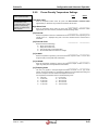
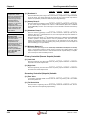
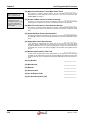
{L1} Prover Upstream Volume
_______________
This entry applies to uni-compact provers only. Enter the upstream water draw volume at base
temperature and pressure, if applicable.
{L1} Prover Downstream Volume
_______________
This entry applies to uni-compact provers only. Enter the downstream water draw volume at
base temperature and pressure, if applicable.
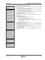
{L1} Over-travel
_______________
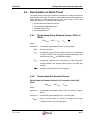
This entry does not apply to Master Meter proving. Enter the estimated amount of flow that the
sphere or piston displaces after activating the first detector switch, multiplied by 1.25.
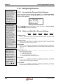
{L2} Inactivity Timer
_______________
Enter the time in seconds before the prove is aborted due to prover inactivity. Make sure you
allow enough time for the sphere or piston to travel between detector switches at the lowest
flow rate expected. When using the Master Meter Method, allow enough time for the amount of
flow to pass through the master meter at the lowest expected flow rate.
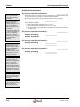
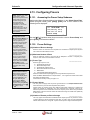
{L1} Prover Diameter
_______________
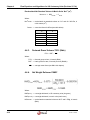
This entry is not applicable to Master Meter proving. Enter the internal diameter of the prover
tube in inches or mm.
{L1} Prover Wall Thickness
_______________
This entry is not applicable to Master Meter proving. Enter the wall thickness of the prover tube
in inches or mm, which is used to calculate the CPSP factor
®
2-54
22/26.74+ 06/07