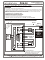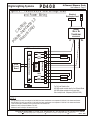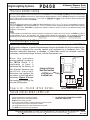
1
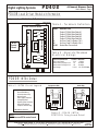
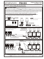
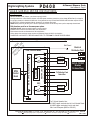
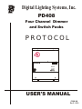
Digital Lighting Systems, Inc.
PD408
Four Channel Dimmer
and Switch Packs
PROTOCOL
PD408
S2 S1
1 2 3 4
USER'S MANUAL
PD408-UM
Rev. E - 02/03
Digital Lighting Systems
PD408
4-Channel Dimmer Pack
User's Manual - Page 1
GENERAL DESCRIPTION
The PD408 is a 4-channel dimmer pack for the PROTOCOL lighting control system. The PD408 dimmer pack contains 4
solid-state dimmers. Power is fed to the PD408 from two 20 Amp. breakers on the same electrical phase. Each breaker
feeds two dimmers and each dimmer is rated for a maximum output current of 8 amperes ( 960 Watts at 120 VAC ). The
PD408 contains two printed circuit boards, the load driver module (LDM) and an INT04 control modules. The dimmers are
triggered by the firing board (INT04).
THE INT04 - (See diagram on Page 2)
The INT04 is a microprocessor based control board with a nonvolatile memory chip, a communications chip, and a
regulated DC power supply. The INT04 also contains, address selectors, LED output monitors and other support circuitry.
The microprocessor is driven by powerful distributed intelligence software which handles all control and communications
functions. The memory chip on the INT04 holds all of the PD408’s pertinent information and settings which include low and
high trim levels for each of the four outputs it controls.
The PD408 does not rely on any shared data source and functions independently of any other system component and
without a central system controller. The PD408 communicates with Protocol system stations and controllers over a single
twisted-pair of wires and can be connected anywhere on the system network bus. This adds convenience and
versatility by allowing PD408 dimmers to be installed close to their loads and/or service panels.
THE LDM (LOAD DRIVER MODULE) - (See Diagram on Page 2)
The LDM is equivalent to four solid-state relays (SSR's) assembled on a single circuit board. The LDM is mounted at the
bottom of the PD408's enclosure which also serves as a heat sink. The relays are triggered by low-voltage signals
generated by the INT04 module. These signals are optically-isolated by the LDM circuitry from all line voltage elements. A
step-down 10 VAC- transformer on the LDM board supplies power to the INT04 module described above.
OTHER INFORMATION- (See diagram Page 4)
Several PD DIMMERS (PD804, PD408 and PD216 dimmer packs) may be daisy-chained together in any combination, up to
a maximum of 63 individually addressed INT04’s (each PD408 and PD216 has 1x INT04 each, each PD804 has two
INT04’s). PD Dimmers are dasiy-chained using the RJPD-6 cables (cat5 network cables) supplied with the units. Each
PD408 has a set of address selectors which must be set to a unique address. Please see Table 4 on Page 9 of this manual or
the PROTOCOL SOFTWARE MANUAL for more information on addressing the PD408 dimmer pack.
DIMMING/SWITCHING - (See Page 8 for more information)
Through the PROTOCOL’s “SOFTPRO” configuration software, each of the PD408 outputs may be independently
configured not to dim. A PD408 may control any combination of dimmed and switched loads.
There is also a HARDWARE lock to ensure circuits do not dim. All four outputs controlled by the INT04 may be configured
not to dim by the installation of a small jumper on the back of the INT04 circuit board. This may be done at the factory or in
the field. This jumper may be removed to allow the future dimming of those outputs. Please see Page 8 for location of this
jumper.
Alternatively, the PD408 may be ordered as a SWITCH-ONLY unit, the PD408-S. This unit has all the same features as the
PD408 except that there is no dimming, and there are no chokes installed inside the unit. All other information in this manual
is the same for both the PD408 and the PD408-S.
7588 NW 8th Street, Miami, Fl. 33126
Copyright
Tel: 305-264-8391 or 1-877-264-8391
Fax: 305-261-6637
2003 Digital Lighting Systems, All rights Reserved Specifications are subject to change without notice. Printed in U.S.A.
PD408-UM
REV. E - 02/03
PD408
Digital Lighting Systems
4-Channel Dimmer Pack
User's Manual - Page 2
PD408 Load Driver Module Information
Figure 1 - PD408 LDM Detail
Earth Ground
Ground
Table 1 - Terminals Definition
LDM Load Driver Module
1
2
NEUTRAL BUS
SSR2
9 VAC
Transformer
SSR's OPTICAL ISOLATORS
INT04
Control
Board
NAME
1
2
3
4
H1
H2
N1-N6
H1
SSR1
SSR3
N1
N2
N3
N4
N5
N6
Table 2 - Absolute Maximum
Electrical Ratings
3
SSR4
DESCRIPTION
Output Of Solid-State Relay #1
Output Of Solid-State Relay #2
Output Of Solid-State Relay #3
Output Of Solid-State Relay #4
Hot Line Feed For Relays 1 & 2.
Hot Line Feed For Relays 3 & 4.
Neutral Bus Connections.
Electrical Characteristic
Terminal Maximum
Relay Load Current
1 to 4
8 Amps.
Input Current For Relays 1 & 2
H1
20 Amps.
Input Current For Relays 3 & 4
H2
20 Amps.
Input Voltage
H1-H2 120 VAC,1-Phase.
4
H2
J3
RJ45 Female Connectors
PD408- INT04 Detail
Components Side
INT04
Table 3 - INT04 Circuit Legend
3
2
4
3
2
1
4
1
5
5
9
F 012
D
BC E
D
BC E
789A
6
F 012
789A
S2
3456
Microprocessor.
Nonvolatile Memory.
Communications Chip.
Quartz Crystal.
Power Supply Capacitor.
Voltage Regulator.
Signal & Power Connector.
Output LED Monitors.
Jumper for switches only
3456
1
2
3
4
5
6
7
8
9
Solder Side
INT04
S1
9
S1
S2
8
8
6
S3
7
7
S1-S2 Address Selectors.
NOTE:
PD408 has one INT04 control board.
7588 NW 8th Street, Miami, Fl. 33126
Copyright
Figure 2 - PD408 / INT04
PROTOCOL Firing board Detail
Tel: 305-264-8391 or 1-877-264-8391
Fax: 305-261-6637
2003 Digital Lighting Systems, All rights Reserved Specifications are subject to change without notice. Printed in U.S.A.
PD408-UM
REV. E - 02/03
PD408
Digital Lighting Systems
4-Channel Dimmer Pack
User's Manual - Page 3
Enclosure Installation
Surface mount the dimmer pack in a well ventilated area where the ambient temperature does not exceed 104° F for
full load operation. Allow 2" of side clearance for proper air circulation and servicing. Installation clearance shall meet
local and/or NEC code requirements. Enclosures may be attached to the wall or other mounting surface by holes in
the heat sink flanges. Refer to the drawings below (FIGURE 3) for the correct dimensions. Conduit shall be pulled to
the top of the dimmer packs.
NOTE
The PD408 may create a slight buzzing noise and should not be located where this is objectionable.
Top View
Bottom View
8.30"
(211 mm)
1/2” and 3/4” Conduit Knockouts
4.12"
(105 mm)
Low Voltage Ports
2"
(51 mm)
2"
(51 mm)
1.380"
(35 mm)
J1
Data
Only
J3
Data &
Power
1.9"
(48 mm)
2.15"
(55 mm)
1.580"
(40 mm)
2.560"
(65 mm)
2.15"
(55 mm)
5" (127 mm)
LDM - Load Driver Module
11.07" (281 mm)
N4 N5 N6
3 4 H2
T1
T4
1
3
2
C
T2
LED's
W1
J3
8
INT04
ADDRESS SELECTORS
LED OUTPUT
MONITORS
C
C
C
10 VAC
Transformer
4
11.75" (298 mm)
N1 N2 N3
H1 1 2
OPTO-ISOLATORS
1
2
3
W2
J1
1 10
4
S2 S1
1 2 3 4
T3
J2
1 10
1
PD408 Front Cover
5" (127 mm)
RJ45 Data Bus Connectors
PD408 ( LDM) Load Driver Module
Figure 3 - PD408 Dimensional Diagram
7588 NW 8th Street, Miami, Fl. 33126
Copyright
Tel: 305-264-8391 or 1-877-264-8391
Fax: 305-261-6637
2003 Digital Lighting Systems, All rights Reserved Specifications are subject to change without notice. Printed in U.S.A.
PD408-UM
REV. E - 02/03
PD408
Digital Lighting Systems
4-Channel Dimmer Pack
User's Manual - Page 4
PD408 Low Voltage Wiring Methods
W1-W2 Shunt Jumpers
Protocol systems with 3 control nodes or less (PS Series stations, DCO, DCI or RAU) do not require an external power supply transformer. Power
for these components can be supplied by one of the PD DIMMER packs. Figure 4 shows the PD408's network ports with its pin assignments.
Installing W1 and W2 connects the 9 VAC transformer output to the network bus via J3. The 9 VAC output is permanently connected to J1. Figure 5
shows a typical small system with one PD Dimmer supplying power to the network. Figure 6 shows a typical system with an external transformer.
System accessories such as extension cables and jumper boards are available from DLS and can simplify network bus connections.
TO AVOID PARALLELING THE OUTPUTS OF SEVERAL TRANSFORMERS IN A PROTOCOL SYSTEM:
(
(
Do not install the jumpers in any of the PD Dimmers when a DB44 panel with an external transformer is used in a system.
Do not install jumpers in more than one PD Dimmer per system when no external transformer is used.
W1
W2
Located On (LDM)
Load Driver Module
PD Dimmer
Transformer
10 VAC OUT
+D
Low Voltage Ports
-D
W1
Bottom View
J3
Data &
Power
J1
Data
Only
Figure 5 -
J3
ONLY ONE SET OF W1-W2 JUMPERS PER SYSTEM.
CONNECT ONLY TO J1 PINS 8 & 9.
CONNECT ONLY TO J3 PINS 1-4.
-D
+D
W2
87654321
CAUTION
PD Dimmer
Transformer
10 VAC OUT
This Port To Be Used For
Data Connections ONLY
10 9 8 7 6 5 4 3 2 1
J1
Figure 4
PD Dimmer Network
Ports Internal Connections.
4 #12 AWG Typical
Install W1 & W2 Jumpers
2 HOT & 2 NEUT.
in the first PD Dimmer ONLY.
To Distribution Panel
Use RJPD-L Network Cable
w/Adaptor for system 8 pin header.
Typical System Powered By
a PD Dimmer Module
4 #12 AWG Typical
2 HOT & 2 NEUT.
To Distribution Panel
To Loads
POWER & DATA
2 Twisted-Pair (4-Wire) Network Cable
May be Carol Cable #C3362 or Equivalent
PD804
PD216
J3 J1
J3 J1
J3 J1
DATA
RJPD-L
Network Cable
DO NOT INSTALL
W1 & W2 Jumpers in any PD Dimmer. 4 #12 AWG Typical
Typical System Powered By
2 HOT & 2 NEUT.
An External Transformer To Distribution Panel Use RJPD-L Network Cable.
To Distribution Panel
DB44
Power & Data
Distribution Panel
RJ45
JACK
RJ45-DB44
DATA
RJPD-L
Network Cable
DATA
RJPD-L
Network Cable
RJPD-L
Network Cable
4 #12 AWG Typical
2 HOT & 2 NEUT.
To Distribution Panel
To Loads
To Loads
PD408
PD804
PD216
J3 J1
J3 J1
J3 J1
#1
PSXX-PT
Pigtails
DATA
4 #12 AWG Typical
2 HOT & 2 NEUT.
To Distribution Panel
To Loads
External Power
Transformer
(For Stations &
Control Modules)
To Loads
PD408
POWER & DATA
RJPD-L
Network Cable
Figure 6
POWER & DATA
2 Twisted-Pair (4-Wire) Network Cable
May be Carol Cable #C3362 or Equivalent
To Loads
#1
W1-W2
PSXX-PT
Pigtails
4 #12 AWG Typical
2 HOT & 2 NEUT.
To Distribution Panel
DATA
DATA
RJPD-L
Network Cable
RJPD-L
Network Cable
DATA
RJPD-L
Network Cable
Network Bus Branch For RAU, DCI-16, DCO-4 Or Other System Components …
7588 NW 8th Street, Miami, Fl. 33126
Copyright
Tel: 305-264-8391 or 1-877-264-8391
Fax: 305-261-6637
2003 Digital Lighting Systems, All rights Reserved Specifications are subject to change without notice. Printed in U.S.A.
PD408-UM
REV. E - 02/03
PD408
Digital Lighting Systems
4-Channel Dimmer Pack
User's Manual - Page 5
PD408 General Wiring Instructions
Wiring Notes
0 DO NOT EXCEED 960 W (8 Amps. ) per dimmer output @ 120VAC.
0 All wiring between the control stations, dimmers, and other system controllers (network bus) is low voltage (NEMA Class 2) and may be
run with two, twisted pair, shielded #18 AWG wire. Control network bus may be Carol Cable #C3362 unless otherwise required. Consult
the PROTOCOL Hardware Installation Manual, Appendix E, for maximum wire length.
PD408 dimmer packs may be fed by one or two 20 A (maximum) branch circuits and may have up to four separately dimmed loads.
0
0 Both breakers must be on the same power phase.
0 CAUTION: DO NOT attempt to parallel outputs to increase capacity.
0 Installations must conform to local and/or NEC code requirements.
0 Each load must have its own Neutral wire for full load operation.
0 All line voltage wires must have copper conductors of adequate Gauge with 90° C wire insulation.
0 POWER EACH LOAD DIRECTLY BEFORE CONNECTING IT TO THE PD408 TO ENSURE PROPER WIRING.
Earth Ground
LDM Load Driver Module
SSR2
ON
1
LOAD #1
2
LOAD #2
ON
2x20 A - 120 VAC
Breakers
On Same Phase
NEUTRAL BUS
N1
9 VAC
Transformer
INT04
Control
Board
SSR3
SSR4
Electrical
Distribution Panel
H1
SSR1
SSR's OPTICAL ISOLATORS
PD C
A
M 408 UT
od -1 IO
el 20 N
sO V
NL AC
Y
Figure 7 - PD408 Typical 120 VAC Wiring.
N2
N3
N4
N5
To Distribution Panel
Neutral Bus
N6
3
LOAD #3
4
LOAD #4
H2
J3
For Full Load Operation Use:
#12 AWG copper conductor wire for Line & Neutral Feeds.
#14 AWG copper conductors in/out to each load.
Max. Load: 8 Amperes (960W at 120 VAC).
7588 NW 8th Street, Miami, Fl. 33126
Copyright
Tel: 305-264-8391 or 1-877-264-8391
Fax: 305-261-6637
2003 Digital Lighting Systems, All rights Reserved Specifications are subject to change without notice. Printed in U.S.A.
PD408-UM
REV. E - 02/03
PD408
Digital Lighting Systems
4-Channel Dimmer Pack
User's Manual - Page 6
PD408-220 General Wiring Instructions
Wiring Notes
0 DO NOT EXCEED 1920 W (8 Amps. ) per dimmer output @ 240VAC.
0 All wiring between the control stations, dimmers, and other system controllers (network bus) is low voltage (NEMA Class 2) and may be
run with two, twisted pair, shielded #18 AWG wire. Control network bus may be Carol Cable #C3362 unless otherwise required. Consult
the PROTOCOL Hardware Installation Manual, Appendix E, for maximum wire length.
PD408 dimmer packs may be fed by one or two 20 A (maximum) branch circuits and may have up to four separately dimmed loads.
0
0 Both breakers must be on the same power phase.
0 CAUTION: DO NOT attempt to parallel outputs to increase capacity.
0 Installations must conform to local and/or NEC code requirements.
0 Each load must have its own Neutral wire for full load operation.
0 All line voltage wires must have copper conductors of adequate Gauge with 90° C wire insulation.
0 POWER EACH LOAD DIRECTLY BEFORE CONNECTING IT TO THE PD408, TO ENSURE PROPER WIRING.
PD
40 C
A
M 8-2 UT
od 20 IO
el /2 N
s O 40
NL VA
Y C
Figure 8 - PD408 Typical 220/240 VAC Wiring.
Earth Ground
LDM Load Driver Module
SSR2
1
LOAD #1
2
LOAD #2
ON
NEUTRAL BUS
N1
9 VAC
Transformer
SSR's OPTICAL ISOLATORS
ON
H1
SSR1
INT04
Control
Board
SSR3
SSR4
Electrical
Distribution Panel
N2
N3
N4
N5
To Distribution Panel
Neutral Bus
2x20 A 220/240 VAC
Breakers
On Same Phase
N6
3
LOAD #3
4
LOAD #4
H2
J3
For Full Load Operation Use:
#12 AWG copper conductor wire for Line & Neutral Feeds.
#14 AWG copper conductors in/out to each load.
Max. Load: 8 Amperes (1920W at 240 VAC).
7588 NW 8th Street, Miami, Fl. 33126
Copyright
Tel: 305-264-8391 or 1-877-264-8391
Fax: 305-261-6637
2003 Digital Lighting Systems, All rights Reserved Specifications are subject to change without notice. Printed in U.S.A.
PD408-UM
REV. E - 02/03
PD408
Digital Lighting Systems
4-Channel Dimmer Pack
User's Manual - Page 7
ON
Figure 9 - PD408-24/12 Low Voltage Load
Electrical
and Power Wiring
Distribution Panel
PD
40 C
AU
8
M -2 TI
od 4 / O
el PD N
s O 40
NL 8-1
Y 2
NEUTRAL
PRIMARY
24v or 12v
Transformer
SECONDARY
X1
X4
LDM Load Driver Module
H1
1
LOAD #1
2
LOAD #2
N1
NEUTRAL BUS
INT04
Control
Board
SSR2
Voltage Divider
Network
SSR's OPTICAL ISOLATORS
SSR1
SSR3
SSR4
N2
N3
N4
N5
N6
3
LOAD #3
4
LOAD #4
H2
J3
For Full Load Operation Use:
#12 AWG copper conductor wire for Line & Neutral Feeds.
#14 AWG copper conductors in/out to each load.
Max. Load per circuit : 8 Amperes (192W at 24 VAC).
NOTES
1
2
3
4
5
With PD408-24 you may use a single 24 VAC-800 VA or better transformer or two separate 24 VAC-400 VA or better transformers.
With PD408-12 you may use a single 12 VAC-400 VA or better transformer or two separate 12 VAC-200 VA or better transformers.
Follow transformer's installation & wiring instructions from manufacturer.
Maximum Load Per Output: 96 Watts at 12 VAC.
Maximum Load Per Output: 192 watts at 24 VAC.
7588 NW 8th Street, Miami, Fl. 33126
Copyright
Tel: 305-264-8391 or 1-877-264-8391
Fax: 305-261-6637
2003 Digital Lighting Systems, All rights Reserved Specifications are subject to change without notice. Printed in U.S.A.
PD408-UM
REV. E - 02/03
Digital Lighting Systems
PD408
4-Channel Dimmer Pack
User's Manual - Page 8
PROTOCOL Address Setting
Up to 63 uniquely addressed INT04 boards (two in each PD804, one in each PD408 and PD216) may be installed in any
one system. Each INT04 must be set to a unique decimal address between 1 and 63. INT04 #63 output 4 is not available
for use. Total number of zones ((63 x 4) -1 = 251). Refer to TABLE 4 On Page 9 of this manual for proper setting of the
address selectors S1 and S2 on the PD408.
Example:
S2 & S1 should be set respectively to 1 & A if the desired address is 26 (1 x 16 + A = 26, A =10). In this example, outputs 1
through 4 of PD408 # 26 are referred to as 26.1, 26.2, 26.3 and 26.4 when configuring buttons on PROTOCOL stations,
using the PROTOCOL “SOFTPRO” programming software. Address used must not be an address already used
elsewhere in the system).
NOTE:
It is also possible to quadruple the maximum number of outputs on a system up to 1004 circuits. An INT04 may have a
decimal address of up to, and including, 252. Please contact factory for more details. For a complete Decimal to
Hexadecimal conversion chart, please refer to Appendix A in the PROTOCOL Hardware and Software Manuals.
Non-Dim Output Setting
Whilst outputs may be programmed to dim or not dim through the “SOFTPRO”
configuration software, in some circumstances it may be preferable for all four outputs in the
PD408 to be configured for non-dim (switch only) operation by a hardware lock. This
prevents inadvertent dimming, or damage, of loads that cannot be dimmed, such as
contactors, mechanical relays, motors, non-dim fluorescent, etc...
Since this procedure
involves adding a jumper to
the INT04 board, it is
preferable to have it
performed by the factory, at
time of order. However, any
qualified electronic
technician can perform the
procedure in the field when
necessary. Figure 10 shows
the location for installing the
non-dim (ND) jumper.
40TNI
3
2
10
Jumper to Ensure
Non-Dim function
of INT04 to be
installed here.
4
1
5
5
1
1
1S
5
2S
8
10
6
7
Figure 10 - PD408 INT04 DETAIL
INT04 Solder (Back) Side
PD408 Installation Check List
BEFORE ENERGIZING THE PD408 MAKE SURE:
0 Loads are tested before connecting to dimmers.
0 Breaker feed lines are on same electrical phase.
0 PD408 has been properly grounded.
0 All line voltage screw terminals are properly tightened to prevent hot spots.
0 Low voltage data lines connections are properly insulated.
0 Low voltage data lines polarity is observed throughout the system.
0 The PD408’s INT04 is set to the right addresses.
7588 NW 8th Street, Miami, Fl. 33126
Copyright
0
ALL KNOCKOUT HOLES MUST BE COVERED
WHEN UNIT IS INSTALLED
Tel: 305-264-8391 or 1-877-264-8391
Fax: 305-261-6637
2003 Digital Lighting Systems, All rights Reserved Specifications are subject to change without notice. Printed in U.S.A.
PD408-UM
REV. E - 02/03
Digital Lighting Systems
PD408
4-Channel Dimmer Pack
User's Manual - Page 9
Table 4 - PD DIMMER Address Selection Information
00 INVALID ADDRESS
01 set S2,S1 to 0,1
02 set S2,S1 to 0,2
03 set S2,S1 to 0,3
04 set S2,S1 to 0,4
05 set S2,S1 to 0,5
06 set S2,S1 to 0,6
07 set S2,S1 to 0,7
08 set S2,S1 to 0,8
09 set S2,S1 to 0,9
10 set S2,S1 to 0,A
11 set S2,S1 to 0,B
12 set S2,S1 to 0,C
13 set S2,S1 to 0,D
14 set S2,S1 to 0,E
15 set S2,S1 to 0,F
16 set S2,S1 to 1,0
17 set S2,S1 to 1,1
18 set S2,S1 to 1,2
19 set S2,S1 to 1,3
20 set S2,S1 to 1,4
21 set S2,S1 to 1,5
22 set S2,S1 to 1,6
23 set S2,S1 to 1,7
24 set S2,S1 to 1,8
25 set S2,S1 to 1,9
26 set S2,S1 to 1,A
27 set S2,S1 to 1,B
28 set S2,S1 to 1,C
29 set S2,S1 to 1,D
30 set S2,S1 to 1,E
31 set S2,S1 to 1,F
32 set S2,S1 to 2,0
33 set S2,S1 to 2,1
34 set S2,S1 to 2,2
35 set S2,S1 to 2,3
36 set S2,S1 to 2,4
37 set S2,S1 to 2,5
38 set S2,S1 to 2,6
39 set S2,S1 to 2,7
40 set S2,S1 to 2,8
41 set S2,S1 to 2,9
42 set S2,S1 to 2,A
43 set S2,S1 to 2,B
44 set S2,S1 to 2,C
45 set S2,S1 to 2,D
46 set S2 S1 to 2,E
47 set S2,S1 to 2,F
48 set S2,S1 to 3,0
49 set S2,S1 to 3,1
50 set S2,S1 to 3,2
51 set S2,S1 to 3,3
52 set S2,S1 to 3,4
53 set S2,S1 to 3,5
54 set S2,S1 to 3,6
55 set S2,S1 to 3,7
56 set S2,S1 to 3,8
57 set S2,S1 to 3,9
58 set S2,S1 to 3,A
59 set S2,S1 to 3,B
60 set S2,S1 to 3,C
61 set S2,S1 to 3,D
62 set S2,S1 to 3,E
63 set S2,S1 to 3,F
NOTES:
00 Decimal (S2,SI = 0,0) is not allowed on any device.
Max PD408 Address: 63 Decimal (S2,S1 = 3,F)
7588 NW 8th Street, Miami, Fl. 33126
Copyright
Tel: 305-264-8391 or 1-877-264-8391
Fax: 305-261-6637
2003 Digital Lighting Systems, All rights Reserved Specifications are subject to change without notice. Printed in U.S.A.
PD408-UM
REV. E - 02/03
LIMITED WARRANTY
Digital Lighting Systems, warrants to the purchaser that its
products have been carefully manufactured and inspected and
are warranted to be free from defects of workmanship and
materials when used as intended. Any abuse or misuse contrary
to normal operation shall void this warranty.
Upon request, replacement unit(s) will be shipped as soon as
available. Unless immediate shipment of replacement
merchandise is requested, Digital Lighting Systems will not
ship replacement merchandise until defective merchandise is
received, inspected, and determined to be defective.
Digital Lighting Systems' obligation under this warranty shall be
limited to replacement or repair of any units as shall within two
years of date of invoice from Digital Lighting Systems, prove
defective; and Digital Lighting Systems shall not be liable for
any other damages, whether direct or consequential. The
implied warranties of merchantability and fitness for a
particular purpose are limited to the duration of the
expressed warranty. Some states do not allow the exclusion of
the limitation of incidental or consequential damages, so the
above limitation or exclusion may not apply to you. This
warranty gives you specific legal rights, you may also have other
legal rights which vary from state to state.
No labor charges in connection with warranty problems will
be reimbursed by Digital Lighting Systems without prior
written approval from the factory.
Defective merchandise may be returned to Digital Lighting
Systems, prepaid, after prior notification has been given and
approval obtained for the return. To obtain prior approval for the
return of the defective items, contact your local Digital Lighting
Systems distributor, representative, or:
Digital Lighting Systems, Inc.
Attn: Customer Service Department
7588 NW 8th Street
Miami, FL 33126
(305) 264-8391
Digital Lighting Systems distributors and representatives have
no authority to change this warranty without written permission.
Digital Lighting Systems reserves the right to determine the
best method of correcting warranty problems.
Digital Lighting Systems, Inc.
7588 NW 8th Street
Miami, FL 33126
www.digitallighting.com
Tel 305-264-8391
Fax 305-261-6637
e-m [email protected]
Printed in U.S.A.
February 2003