1
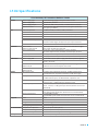
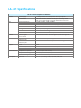
User Manual
Installation and Operation
LT-84 STATIONARY IR TRANSMITTER/RADIATOR COMBO
LA-141 STATIONARY IR EXPANSION RADIATOR
PAGE 0
Table of Contents
Safety Cautions!.....................................................................................................................................................................................2
Recycling Instructions.........................................................................................................................................................................2
Compliance Information....................................................................................................................................................................3
Compliance Notice, FCC and Industry Canada Statements...............................................................................................3
System Overview...................................................................................................................................................................................4
LT-84 ListenIR Transmitter/Radiator Combo............................................................................................................................5
.Package Contents..............................................................................................................................................................................5
LT-84 Rear View Quick Reference...................................................................................................................................................5
LA-141 ListenIR Expansion Radiator.............................................................................................................................................6
.Package Contents..............................................................................................................................................................................6
LA-141 Rear View Quick Reference................................................................................................................................................6
LT-84 and LA-141 Coverage................................................................................................................................................................7
Designing a System...............................................................................................................................................................................9
Flexible Mounting Hardware Instructions.............................................................................................................................. 10
.Mounting Hardware Kit................................................................................................................................................................10
.Mounting Provision Thread ¼” x 20 (6mm x 1.0 thread)..................................................................................................... 10
.Wall Surface Mounting Example................................................................................................................................................11
.Ceiling Surface Mounting Example............................................................................................................................................ 11
.Mounting Two Units with Linking Mount Example................................................................................................................ 11
Interconnection and Control........................................................................................................................................................12
.Connection of the External Power Adaptor............................................................................................................................ 12
.Connection of External Audio Sources..................................................................................................................................... 13
I./R Frequency Selection/Control................................................................................................................................................14
.Stationary IR Expansion Link RJ-45 Connections................................................................................................................... 15
.Indicator Lights...............................................................................................................................................................................16
.Troubleshooting.............................................................................................................................................................................17
.LT-84 Specifications.......................................................................................................................................................................18
.LA-141 Specifications....................................................................................................................................................................19
Warranty Information......................................................................................................................................................................20
Technical Support Contact.............................................................................................................................................................21
PAGE 1
Safety Cautions!
CAT-5e Cable Safety:
Do NOT Plug the LT-84 (Stationary IR Transmitter/Radiator Combo) CAT-5e cable into anything other than an
LA-141 (Stationary IR Expansion Radiator). The LT-84 CAT-5e Expansion Output RJ-45 connection is proprietary
and is not compatible with Ethernet or any other system. Failure to comply with this caution can damage the
LT-84, LA-141 or other equipment and will void the warranty.
Hearing Safety:
This product is designed to amplify audio to a high volume level which could potentially cause hearing damage
if used improperly. To protect your hearing, make sure the volume is turned down before putting on the ear
speaker or headphones, then adjust the volume up to the minimum setting require to hear clearly. Do not allow
children or other unauthorized individuals to have access to this product without supervision.
Medical Device Safety:
Before using this product with an implantable or other medical device, consult your implantable or other
medical device physician or manufacturer. Always make sure you are using this product in accordance with
the safety guidelines established by your physician or the implantable device manufacturer.
Recycling Instructions
Recycling:
Help Listen Technologies protect the environment by taking the time to dispose of your equipment properly.
Product Recycling Instructions:
Please do NOT dispose of your Listen Technologies equipment in the household trash. Please take
the equipment to an electronics recycling center; OR, return the product to the factory for proper
disposal.
Battery Recycling Instructions:
Please do NOT dispose of batteries in the household trash. Please take the batteries to a
retail or community collection point for recycling.
PAGE 2
Compliance Information
No FCC license or radio approval is required with this equipment.
Compliance Notice,
FCC and Industry Canada Statements
Compliance Notice
This device complies with part 15 of the FCC Rules. Operation is subject to the following two conditions:
(1) These devices may not cause harmful interference, and (2) these devices must accept any interference
received, including interference that may cause undesirable operation.
FCC Statement
This equipment has been tested and found to comply with the limits for a class B digital device, pursuant to
part 15 of the FCC Rules. These limits are designed to provide reasonable protection against harmful interference
in a residential installation. This equipment generates, uses and can radiate radio frequency energy and if not
installed and used in accordance with the instructions, may cause harmful interference to radio communications.
However, there is no guarantee that interference will not occur in a particular installation. If this equipment does
cause harmful interference to radio or television reception, which can be determined by turning the equipment
off and on, the user is encouraged to try to correct the interference by one or more of the following measures:
•
•
• •
Reorient or relocate the receiving antenna.
Increase the separation between the equipment and receiver.
Connect the equipment into an outlet on a circuit different from that to which the receiver
is connected.
Consult the dealer or an experienced radio/TV technician for help.
The user is cautioned that changes and modifications made to the equipment without the approval of
manufacturer could void the user’s authority to operate this equipment.
Industry Canada Statement
This equipment complies with ICES-003 class B.
CAN ICES-3 (B)/NMB-3(B)
PAGE 3
System Overview
The LT-84 is an all-in-one two channel infrared (IR) transmitter and radiator (Transmitter/Radiator Combo) packed
into a single mountable enclosure. The LT-84 IR radiator is located behind the IR transparent front panel and
provides line of sight coverage of 5,000 ft² (465 m²).
The LT-84 is perfect for high-quality audio applications like assistive listening, audio description or language
interpretation in corporate boardrooms, courtrooms, training rooms, classrooms, and theaters. Its flexible audio
inputs accept microphone, consumer and line level inputs which are all mixed to the modulated IR transmission.
IR receivers then detect the modulated IR transmission and convert the IR signals back into an audio signal and
presents it to headphones.
For better line of sight coverage or for coverage in larger areas the LT-84 can be combined with up to four (4)
LA-141 Listen IR Expansion Radiators. The LA-141s are connected in a daisy chain fashion to the LT-84 via a 24
AWG unschielded CAT-5e cable. A maximum of two (2) LA-141s can be connected to each expansion link output
on the LT-84 with a maximum cable length of 100 ft. (30 m).
PAGE 4
LT-84 ListenIR Transmitter/Radiator Combo
Package Contents
LT-84 ListenIR Transmitter/Radiator Combo
LA-210 12 VDC Universal Power Supply
Power Cord
LA-344 Mounting Hardware
(2) Phoenix Type Connectors
Quick Start Guide
LA-303 Small Room Signage Kit
LT-84 Stationary IR Transmitter/Radiator Combo
Power Cord
(2) Phoenix Type
Connectors
LA-210 12 VDC Universal Power Supply
LA-344 Mounting Hardware
Hearing Assistance Available
Asistencia auditiva a su disposición
Aide à l’audition
Pan & Tilt
1/4” x 20
Mount Adaptor
Ceiling Tile
Mounting Plate
All Thread Piece
This facility is equipped with a hearing assistance system.
Please ask for a receiver.
2” Extension Bars
Este establecimiento está equipado con un sistema
de asistencia auditiva. Por favor solicite un receptor.
Cet éstablissement est équipé d’un système d’aide
à l’audition. S’il vous plaît demandez un récepteur.
Pan and Tilt
Lock Screw
Mounting Plate
Cover
Quick Start Guide
LA-303 Small Room Signage Kit
Hex Key
Flush Mounting Plate
LT-84 Rear View Quick Reference
LT-84 Rear View
Safety/Security
Cable Slot
Power Input
Mic
Input
RCA Input
(Stereo)
Power Switch
Indicator Lights
On/Off
PAGE 5
Frequency
Selector
Level Control
Knob
Line Input
Level
Indicators
Mic
Input
Level Control
Knob
RCA Input
(Stereo)
Transmission
On/Off
Line Input
Frequency
Selector
Level
Indicators
Expansion Link
Output RJ-45
Amber LED
(Status Indicator)
Green LED
(Power Indicator)
Transmission
On/Off
LA-141 ListenIR Expansion Radiator
Package Contents
LA-141 ListenIR Expansion Radiator
(1) 25 ft. (7.6 m) CAT-5e Cable
LA-344 Mounting Hardware
Quick Start Guide
LA-141 Listen IR Transmitter/Radiator Combo
LA-344 Mounting Hardware
(1) 25 ft. (7.6 m) CAT-5e Cable
Pan & Tilt
1/4” x 20
Mount Adaptor
Ceiling Tile
Mounting Plate
All Thread Piece
2” Extension Bars
Pan and Tilt
Lock Screw
Mounting Plate
Cover
Hex Key
Flush Mounting Plate
Quick Start Guide
LA-141 Rear View Quick Reference
LA-141 Rear View
Expansion Link
In/Out RJ-45
Safety/Security
Cable Slot
Indicator Lights
On/Off Switch
Channel 1
Delay
Compensation
Channel 2
Delay
Compensation
Amber LED
(Status Indicator)
Green LED
(Power Indicator)
PAGE 6
LT-84 and LA-141 Coverage
The units emit a beam of infrared light from the front panel. Infrared light is not visible to the human eye. Below
is a scaled diagram of the typical line of sight IR pattern or “footprint” emitted from the units. When using a unit in
single channel transmit mode the coverage area is 5,000 ft² (465 m²) and in 2 channel transmit mode the coverage
area is 2,500 ft² (232 m²). Use the diagrams below when evaluating a given space to determine the number of
units required and placement of those units for best line of sight coverage.
Figure 1: LT-84 or LA-141 Single Unit Coverage Pattern “footprint” 1 & 2 Channel Transmission
Figure 2: LT-84 and LA-141 Single Channel Coverage Pattern “footprint” from same emission point
(40% increase)
PAGE 7
Figure 3: LT-84 and LA-141 Single Channel Coverage Pattern “footprint” Overlapping 50 ft. (15.24 m) apart
Figure 4: Single Channel Coverage Pattern “footprint” same emission point at an angle of 15 degrees
Figure 5: Single Channel Coverage Pattern “fooptrint” same emission point at an angle of 30 degrees
PAGE 8
Designing a System
Use the following steps when designing an IR system:
1.
2.
3.
Determine the number of audio channels that will be used (1 or 2).
Determine the room size and shape.
Use the room size and shape information along with the appropriate 1 or 2 channel coverage
pattern footprint to overlay the footprint on the room dimensions and determine the number of units required and the placement of those units to cover the desired listening audience.
Best performance is achieved:
•
•
•
•
When radiators face and have direct line of sight to audience.
When a system provides over-lapping coverage (like a sprinkling system).
When special coverage is provided for shaded areas like under a balcony.
When mounted above and angled down into the listening audience
9 – 16 ft. (2.8 - 4.9 m) high and at an angle between 10 and 30 degrees.
Radiator Balcony
Four Corners Radiators
PAGE 9
Dual Radiator Diagram
Flexible Mounting Hardware Instructions
LT-84 & LA-141 Universal Mounting Hardware Kit
A universal mounting kit is supplied to simplify the mounting process for the LT-84 and LA-141. This kit
contains the components for mounting to a flat surface wall or ceiling, attaching to a drop ceiling grid
T bar or connecting units together. Please refer to the diagram below.
Mounting Hardware Pieces
Pan & Tilt
1/4” x 20 Mount Adaptor
Ceiling Tile
Mounting Plate
All Thread Piece
2” Extension Bars
Pan and Tilt
Lock Screw
Mounting Plate Cover
Hex Key
Flush Mounting Plate
Threaded Mounting Socket ¼” x 20 (6mm x 1.0 thread)
The LT-84/LA-141 have a ¼” x 20 thread (6mm x 1.0 thread) hole located in the bottom and top of the enclosure.
This threaded hole is used to attach the units to the provided universal mounting kit or to any user provided
mounting device using a ¼” x 20 thread (6mm x 1.0 thread). Refer to the diagrams below of ceiling and wall
mounting using the universal kit provided.
1/4” x 20 Thread Mounting Hole
Top and Bottom
PAGE 10
Wall Surface Mounting Example
Wall Mount
Ceiling Surface Mounting Example
Ceiling Mount
Solid ceiling surface or T bar grid mounting
Mounting Two Units with Linking Mount Example
Linking Mount
or
PAGE 11
Interconnection and Control
The LT-84 is a two (2) channel I/R Transmitter/Radiator. Separate input and control sections are located on the rear
panel of the LT-84 to accommodate the two (2) channel transmission. Refer to the diagram below for location of
these two separate channel control areas, power input, and expansion link output RJ-45s.
Expansion Link
Output RJ-45
Power Input
Connections and Setup
Channel 1
Connections and Setup
Channel 2
Connection of the external power adaptor
Power for the LT-84 is provided by a 12 VDC 4A universal switching power supply. The diagram below highlights
the connection point for power and the associated power switch.
Power Switch –
Indicator Lights On/Off
Power Input
Barrel Connector
1.
The supplied power adaptor is an in line universal switching power supply that can be used with
an AC power source from 100 – 240 VAC, 50/60Hz. The overall length of the line cord and DC
power cable is 10 ft. (3 m). Note that if the LT-84 is located further than 10 ft. (3 m) from the nearest AC outlet, provisions will need to be made for extending the power.
2. The Power Switch On/OFF control is a three (3) position switch located to the right of the power input connector.
a. In the “top” position the unit is turned ON and the indicator lights are active.
b. In the “middle” position the unit is turned ON and the indicator lights are NOT active.
c. In the “bottom” position the LT-84 and LA-141 are OFF.
PAGE 12
Connection of External Audio Sources
Each channel has the option for three (3) audio connections. The interconnection and control of each channel
is identical. We will refer to the interconnection and control of channel 1 only. Refer to the diagram below for
connection of audio sources.
Mic
Input
Level Control
Knob
RCA Input
(Stereo)
Line Input
Level
Indicators
View of Channel 1 audio interconnections and control
1. The left side of the channel interconnection is a 3.5mm tip sleeve condenser microphone level input. This
is a -30 dBu nominal microphone level input with a 5 VDC bias supply. Any of Listen’s microphones may
be connected to this input. Note that a 3.5mm extension cable will most likely be required when using the
microphone input.
2. RCA unbalanced stereo audio input is provided through two phono connectors. These are a -10 dBu
nominal level unbalanced input and the two inputs are summed together.
3. A balanced audio input is provided through the three (3) pin Phoenix type terminal connector. This is a
+4 dBu nominal level balanced input.
4. To the right of the balanced input is the audio input level adjustment control. This control rotates clockwise
to increase the audio level, counter clockwise to decrease the audio level. From the factory this adjustment
is set fully counter-clockwise.
5. A red and green LED located to the right of the level adjustment is used to determine the proper level
adjustment. With a typical audio source connected adjust the audio level adjustment up or down until the
green LED is solid green and the red LED flickers red occasionally with peaks in the audio. Note: LT-84 will enter Power Save Mode after 15 minutes of no audio. This state is indicated by the Green
LED (Power indicator) on the expansion link output RJ-45 flashing slowly.
PAGE 13
IR Frequency Selection/Control
The LT-84 provides the ability for the user to select the IR carrier frequency to be used for transmission of the
audio connected to the channel input. The carrier frequencies are at 2.3MHz, 2.8MHz, 3.3MHz, and 3.8MHz.
Refer to the diagram below for selection and control of the IR carrier.
IR Frequency
Selection
IR Transmission
On/Off Control
1. Located on the right side of the channel interconnection and control is the IR frequency selection.
This is a four (4) position rotary selection switch. With the switch rotated to the counter clockwise stop,
the IR frequency is set to 2.3MHz. Position 2 is 2.8MHz, position 3 is 3.3 MHz, and position 4 is 3.8MHz.
2. The IR Transmission On/Off switch is used to activate the IR signal transmission for this channel. In the “up”
position the IR signal is active. In the “down” position the IR signal for this channel is NOT active.
Note: If both channels are active and set to the same frequency the LT-84 will indicate an error state and enter
Power Save Mode. Power save mode is indicated by the Green Power Indicator LEDs flashing slowly. The error
mode is indicated by 4 quick flashes on the Red Level Indicator LEDS and then turning off for 2 second, repeated
until the error is resolved.
PAGE 14
Listen IR Expansion Link RJ-45 Connections
The coverage area of the LT-84 can be extended by adding up to four (4) LA-141 Expansion Radiators.
A maximum of two (2) LA-141s can be connected to each Expansion Link output RJ-45 on the LT-84 with a
maximum daisy chained CAT-5e cable length of 100 ft. (30.5 m). CAT-5e cable must be at least 24 AWG!
Refer to the diagram below.
Amber LED
(Status Indicator)
Expansion Link
Output RJ-45
LT-84
Green LED
(Power Indicator)
Set Delay Compensation. For a single channel
application, set both Channel 1 and 2 Delay Compensation switches to the same setting. For a two
channel application, set Delay Compensation
switches channel 1 and 2 independently. Pick
appropriate frequency row then move over to
the overall cable distance from the LT-84 to the
LA-141 being set, this is the switch setting.
PAGE 15
Delay Compensation Switch Setting
10 to 19 ft.
20 to 29 ft.
30 to 39 ft.
40 to 49 ft.
Cable Length 1 to 9 ft.
3 to 2.8 m
3 to 5.8 m
6 to 8.8 m 9.1 to 11.9 m 12.2 to 14.9 m
2.3 MHz
0333 3
2.8 MHz
3333 3
3.3 MHz
3322 2
3.8 MHz
2222 2
Cable Length 50 to 59 ft.
15.2 to 18 m
60 to 69 ft.
18.3 to 21 m
70 to 79 ft.
80 to 89 ft.
90 to 100 ft.
21.3 to 24 m 24.4 to 27.1 m 27.4 to 30.5 m
2.3 MHz
3333 3
2.8 MHz
2222 2
3.3 MHz
2211 1
3.8 MHz
1111 0
Indicator Lights
Input Level indicators Channel 1 and Channel 2:
Green LED Off and Red LED Off – Low or no audio present, power switch
is off or in the indicator lights off position
Green LED solid and Red LED flashing – Audio is present
and adjusted properly on the input
Green LED Off and Red LED Ch1 and Ch2 flashing quickly 4 times
with a 2 second off state, repeated – Frequency selectors are set
to the same frequency and transmission switch is active on both
channels (error state) Level
Indicators
LT-84 RJ-45 Green and Amber LED Indicators:
Green LED OFF – Power switch is Off or in the indicator
lights Off position, bad power supply or not connect to
AC power outlet
Amber LED
(Status Indicator)
Expansion Link
Output RJ-45
Green LED solid – Power is applied to the unit
Green LED flashing – Unit has entered Power Save Mode
Amber LED Off – No Carrier present or problem with IR LEDs
Amber LED solid – Carrier is present and unit is actively
transmitting IR
LA-141 RJ-45 Green and Amber LED Indicators:
Green LED OFF – LT-84 power switch is Off, LT-84 has
entered Power Save Mode, LA-141 indicator lights switch
in Off position, bad CAT-5e cable or cable is too long
Green LED
(Power Indicator)
Expansion Link
In/Out RJ-45
Amber LED
(Status Indicator)
Green LED solid – Power is applied to the unit
Amber LED Off – No Carrier present, bad CAT-5e cable
or cable is too long, problem with IR LEDs
Amber LED solid – Carrier is present and unit is actively
transmitting IR
Green LED
(Power Indicator)
PAGE 16
Troubleshooting
The LT-84 Green LED “Power Indicators” are not lit:
•
Make sure the power supply is plugged into the LT-84 and plugged into an AC outlet.
•
Make sure the electrical outlet is on or if using a power strip make sure it is turned on.
•
Make sure the Power Switch is set to the Indicators Lights “On” position.
•
Make sure the 12 VDC in-line switching power supply is lit green and that it is working.
The LT-84’s Ch1 or Ch2 Audio “level Indicators” do not light:
•
Make sure the LT-84 is plugged in.
•
Make sure the Power Switch is set to the Indicators Lights “On” position.
•
Make sure the audio source is active and that audio is presented to the audio input.
•
Make sure the audio input is connected properly and that the level control knob is turned clockwise.
Receivers do not pick up audio:
•
Make sure the LT-84 as not entered Power Save Mode due to no active audio for 15 minute.
•
Make sure the audio source is playing and plugged into the LT-84 properly.
•
Make sure the green level indicator is solid green and the red level indicator occasionally
flashes red with audio peaks.
•
Make sure the receivers are operating on the same channel / frequency as the LT-84.
•
Make sure the LT-84 is transmitting IR light and that the IR light is not being blocked by objects.
•
If some of the receivers work but others do not, check the battery and/or earphones.
Receiver’s audio is weak and noisy:
•
Make sure the green level indicator is solid green and the red level indicator occasionally flashes red with audio peaks.
•
Make sure LA-141s are connected properly and that the power and status indicator LEDs
are lit solid
•
Make sure the LT-84 and LA-141s IR light is focus towards the listening audience.
•
Make sure the receiver is directed towards the LT-84 and LA-141s.
•
Make sure the all units are transmitting IR light and that the IR light is not being blocked by objects.
•
Add more LA-141s to increase the overall coverage.
PAGE 17
LT-84 Specifications
LT-84 Stationary IR Transmitter/Radiator Combo
Power
Power Supply Type
Power Supply Input
Power Supply Output
Power Line Cord
RF
Carrier Frequencies
Number of Channels
Modulation
IR Power
Coverage Area
Expansion Link Output
Power Save Mode
Controls
Power Switch - Indicator Lights On/Off
Level Control Knob
Frequency Selector
Transmission ON/OFF
Indicators
Power Supply LED
Audio Level Indicators
Green LEDs - Power Indicator RJ-45
Amber LEDs - Status Indicator RJ-45
Audio
Microphone Input
Line Input
Line Input
Frequency Response
Total Harmonic Distortion
Signal-to-Noise Ratio
Physical
Color Dimensions (H x W xD)
Weight
Unit Weight with Power Supply
Shipping Weight
Environmental Temperature - Operation
Temperature - Storage
Relative Humidity
Compliance Standards
In-line switching supply, Listen part number LA-210
100-240 VAC, 50-60 Hz
12 VDC, 4A, 48W, center positive, 2.5 mm ID barrel connector
North America, Type B, (LT-84-01) Asia, UK, Type G, (LT-84-02) Euro Type J, (LT-84-03)
2.3 MHz, 2.8 MHz, 3.3 MHz, 3.8 MHz, selectable
Two (2) Channels
FM Wideband, ±50kHz deviation max, 50 μS pre-emphasis
1.49 W
5,000 ft² (465 m²) single channel when used with Listen Receivers
Two (2) RJ-45 connectors, CAT-5e cable 24 AWG, 100 ft.
maximum cable length, two (2) LA-141s per output connector
Shuts off carrier when no audio is present for 15 minutes
Three (3) position switch - Power OFF, Power ON-Indicator Lights
OFF, Power ON-Indicator Lights ON
Audio taper rotary potentiometer, counter-clockwise
decreases input mix level, clockwise increases input mix level
Four (4) position rotary switch (2.3 MHz, 2.8 MHz, 3.3 MHz, 3.8 MHz)
Two (2) position switch (transmission OFF, transmission ON)
Green LED on in-line power supply indicates AC power is applied
Green LED indicates Audio presence and Red LED indicates peaks in the audio
Solid Green indicates power is applied to unit, flashing
indicates unit has entered power save mode
Solid Amber indicates carrier is present and IR is being transmitted
3.5 mm (0.14in.) Tip/Sleeve connector, -30 dBu nominal input, +14 dB headroom, impedance 4.4k Ohms, 5 VDC bias supply
Stereo/Mono Input. Two (2) RCA Phono connectors, unbalanced,
-10 dBu nominal input, +14 dB headroom, impedance 10k
Mono Input. Pheonix Type connector, balanced, + 4 dBu
nominal input, +14 dB headroom, impedance 100k
20 Hz - 20 kHz (+/- 1 dB) Line Input
63 Hz - 15 kHz (+/- 3 dB) System Specification (wireless end-to-end
with LR-44)
<0.1% (THD) Line Input
<2% (THD) System Specification (wireless end-to-end with LR-44)
>70 dB (SNR) Line Input
>60 dB (SNR) System Specification (wireless end-to-end with LR-44)
Black
1.5 x 10.7 x 4.1 in. (3.81 x 27.2 x 10.5 cm)
0.8 lbs. (0.4 kg)
1.4 lbs. (0.7 kg)
3.4 lbs. (1.54 kg)
14 °F (-10 °C) to +104 °F (40 °C)
-4 °F (-20 °C) to +122 °F (50 °C)
0 to 95% relative humidity, non-condensing
FCC Part 15, Industry Canada, CE, RoHS, WEEE, CUL
PAGE 18
LA-141 Specifications
LA-141 Listen IR Expansion Radiator
Power
Power Supply
12 VDC, provided via LT-84 Expansion Link Output RJ-45s
Current Draw
600 mA per LA-141, maximum of two (2) LA-141s daisy chained with CAT-5e cable 24 AWG to each LT-84 Expansion Link Output
RF
Carrier Frequencies
2.3 MHz, 2.8 MHz, 3.3 MHz, 3.8 MHz
Number of Channels
Two (2) Channels
Modulation
FM Wideband, ±50kHz deviation max, 50 μS pre-emphasis
IR Power
1.49 W
Coverage Area
5,000 ft² (465 m²) single channel when used with Listen Receivers
Expansion Link In/Out
Two (2) RJ-45 connectors, CAT-5e cable 24 AWG, dasiy chain of 100 ft. maximum cable length
Power Save Mode
Shuts off carrier when no audio is present for 15 minutes
Controls
Indicator Lights Two (2) position switch - Indicator Lights OFF, Indicator Lights ON
On/Off Switch
Indicators
Green LEDs - Power Solid Green indicates power is applied to unit
Indicator RJ-45
Amber LEDs - Status Solid Amber indicates carrier is present and IR is being transmitted
Indicator RJ-45
Physical
Color Black
Dimensions (H x W xD)
1.5 x 10.7 x 3.9 in. (3.81 x 27.2 x 10.5 cm)
Weight
0.6 lbs. (0.28 kg)
Shipping Weight
3.0 lbs. (1.4 kg)
Environmental
Temperature - Operation
14 °F (-10 °C) to +104 °F (40 °C)
Temperature - Storage
-4 °F (-20 °C) to +122 °F (50 °C)
Relative Humidity
0 to 95% relative humidity, non-condensing
Compliance Standards
FCC Part 15, Industry Canada, CE, RoHS, WEEE, CUL
PAGE 19
Warranty Information
Listen Technologies Corporation (Listen) warrants its transmitters and receivers (LT-82, LT-700, LT-800, LT-803,
LR-100, LR-42, LR-44, LR-200, LR-300, LR-400, LR-500, LR-4200, LR-5200) to be free from defects in workmanship
and material under normal use and conditions for the useful lifetime of the product from date of purchase.
Listen warrants it’s Listen IR Radiators (LA-140, LT-84, LA-141) to be free from defects in workmanship and material
under normal use and conditions for three years from the date of purchase.
Listen warrants its Digital IR products (T8, T16, RAD25, R8, R32) to be free from defects in workmanship and
material under normal use and conditions for two years from the date of purchase.
Listen warrants its Noise Canceling Microphone (LA-270) to be free from defects in workmanship and
material under normal use and conditions for one year from date of purchase.
Listen warrants it’s Charging/Carrying Cases (LA-306, LA-311, LA-313, LA-317, LA-318, LA-319, LA-320,
LA-321, LA-322, LA-323, LA-324, LA-325, LA-380, LA-381) to be free from defects in workmanship and material
under normal use and conditions for one year from date of purchase.
All other products and accessories are warranted for 90 days from date of purchase.
This warranty is only available to the original end purchaser of the product and cannot be transferred.
Warranty is only valid if warranty card has been returned within 90 days of purchase. This warranty is void if
damage occurred because of misuse or if the product has been repaired or modified by anyone other than a
factory authorized service technician. Warranty does not cover normal wear and tear on the product or any other
physical damage unless the damage was the result of a manufacturing defect. Listen is not liable for consequential
damages due to any failure of equipment to perform as intended.
Listen shall bear no responsibility or obligation with respect to the manner of use of any equipment sold by it.
Listen specifically disclaims and negates any warranty of merchantability or fitness of use of such equipment
including, without limitation, any warranty that the use of such equipment for any purpose will comply with
applicable laws and regulations. The terms of the warranty are governed by the laws of the state of Utah.
In the first ninety days after purchase, any defective product will be replaced with a new unit. After ninety days,
Listen will at its own discretion either repair or replace transmitters and receivers with a new unit or a unit of
similar type and condition. Product that is not covered under warranty shall be repaired or replaced with a unit
of similar type and condition based on a flat fee. Contact Listen for details.
This limited warranty, prices, and the specifications of products are subject to change without notice.
PAGE 20
Technical Support Contact
If technical service is needed, please contact Listen. Pre-authorization is required before returning
Listen products. If products were damaged in shipment, please contact the carrier, then contact Listen
for replacement or repair requirements payable by the carrier.
Listen’s corporate headquarters are located in Bluffdale, Utah U.S.A. and are open Monday through
Friday, 8am to 5pm Mountain Time.
LISTEN TECHNOLOGIES
14912 Heritage Crest Way
Bluffdale, Utah 84065-4818
+1.801.233.8992
+1.800.330.0891 North America
+1.801.233.8995 Fax
[email protected]
www.listentech.com
PAGE 21
NOTES:
PAGE 22
14912 Heritage Crest Way
Bluffdale, Utah 84065-4818
+1.801.233.8992
+1.800.330.0891 North America
+1.801.233.8995 Fax
[email protected]
www.listentech.com
© 2014 Listen Technologies Corporation® All Rights Reserved
For further details regarding use, adjustment, or programming of your Listen products visit our website at
www.listentech.com/support-manuals or contact Listen at +1.801.233.8992 or 1.800.330.0891.
20141202