1
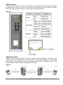
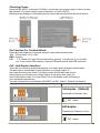
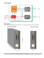
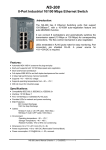
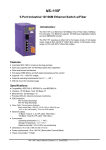
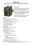
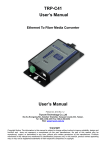
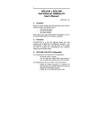
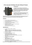
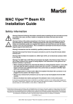
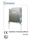
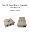
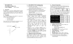
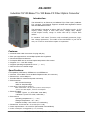
NS-200FC
Industrial 10/100 Base-T to 100 Base-FX Fiber Optics Converter
Introduction:
The NS-200FC is an Ethernet (10/100Base-TX) to Fiber Optic (100BaseFX) converter. The Ethernet supports 10/100M auto-negotiation feature
and auto MDI/MDIX function.
The NS-200FC operates at either half or full duplex mode. In full
duplex mode, range is 2km with 62.5/ 125µm fiber cables;
in half duplex mode, range is 412m with 62.5/ 125µm fiber
cables.
It contains "soft start" function with overload protection, highlow voltage protection. The width of the NS-200FC is just 32.30
mm, so it can be used where space is important.
Features:
•
•
•
•
•
•
•
Automatic MDI / MDI-X crossover for plug-and-play
Each port supports both 10/100 Mbps speed auto negotiation
Store-and-forward architecture
Full duplex IEEE 802.3x and half duplex backpressure flow control
Supports +10 ~ +30V DC voltage
Supports operating temperatures from 0 ℃ ~ +70 ℃
DIN rail mount for industrial usage
Specifications:
• Compatibility: IEEE 802.3, IEEE802.3u, And IEEE802.3x
• Interface: 10/100 Base-T and 100 Base-FX(Multi-mode; SC connector)
• Ethernet Port: 10/100 Mbps x 1
• Provides LEDs for network and power monitoring
• ESD Protection:
8KV Contact Discharge
15KV Air-Gap Discharge
•
Fiber Optic Transmission distance:
Multi mode fiber: 50/125, 62.5/125 or 100/140 µm
, 412 m for half duplex, 2 km for Full duplex
• Ethernet Cables:
10 Base-T (Cat.3, 4, 5 UTP cable; 100m Max.)
100 Base-T (Cat.5 UTP cable; 100m Max.)
• Environment:
Operating temperature: 0 ℃ ~ +70 ℃
Storage Temperature: –20 ~ +85 ℃
Relative Humidity: 10% to 90% non-condensing
• Dimensions: 32.30 x 99.00 x 77.50 mm (W x H x D)
• Power requirements: +10 to 30V DC (Removable Terminal Block)
•
Power consumption: 0.12A@24Vdc (+/- 5%, arrowed)
NS-200FC User’s Manual (Version 1.0, Feb/2006) --------------- 1
LED functions:
Standard RJ45 female connectors are provided. A standard RJ45 plug cable is necessary
to connect your device to the unit since switch that supports auto crossover. Figure1
shows the LED indicator functions. The module includes an internal.
Figure1:
Application Note:
Figure2 shows common media conversion system network topologies. This figure is a
simple end-to-end configuration; it is easy way to verify proper operation of the media
converter(s), assuming that the Network Interface Cards (NIC’s) or Ethernet ports in each
PC/workstation end link partner are properly configured.
Figure2:
NS-200FC User’s Manual (Version 1.0, Feb/2006) --------------- 2
Checking Power:
Since the NS-200FC consumes 2.9W Max, ensure that your power supply is able to meets
this demand. The Input voltage range is between +10 and +30VDC.
External power supply is connected using the removable terminal block as shown below:
Pin Function For Terminal Block:
External power supply is connected using the removable terminal block:
+Vs : Power input +10 to +30V
GND : Ground
F.G. : F.G. stands for Frame Ground (protective ground). It is optional. If you use this
pin, it can reduce EMI radiation; improve EMI performance and ESD protection.
Full / Half-Duplex Selection:
There are two modes of data transmissions, full-duplex and half-duplex transmission.
The data can be transmitted in both directions on a single carrier at
the same time when you select Full-duplex mode. But the data can only be
transmitted in one direction on a single carrier at the same time when you
select Half-duplex mode. You may select Full or half-duplex mode according to
your equipment requirement.
You can configure full or half-duplex NS-200FC via DIP –Switch. (Default: full-duplex).
DIP-Switch
Description
Full-duplex ( Default)
Transmission Distance: 2km
DIP –Switch
Half-duplex
Transmission Distance: 412m
DIP –Switch
NS-200FC User’s Manual (Version 1.0, Feb/2006) --------------- 3
Block Diagram:
Dimensions:
The width of the NS-200FC is just 32.30 mm, so it can be used where space is important.
NS-200FC User’s Manual (Version 1.0, Feb/2006) --------------- 4