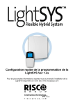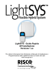
1
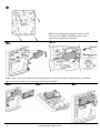
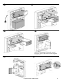
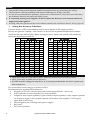
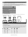
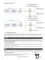
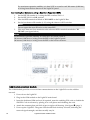
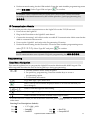
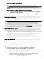
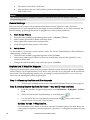
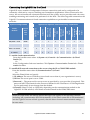
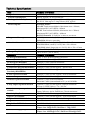
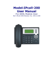
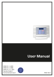
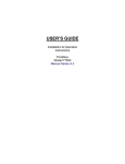
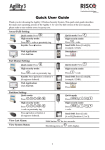
Quick Installation Guide LightSYS Ver 2.xx For detailed information please refer to the full LightSYS Installer Manual provided on our website: www.riscogroup.com Note: For mounting the LightSYS inside a metal enclosure ( RP432BM, RP432BM1) refer to the instructions supplied with the box. B A Note: 1.5A PS can be mounted inside either the plastic enclosure RP432B or the metal box RP432BM. 4A PS can be mounted only in the metal enclosure RP432BM1. A 2 B LightSYS Quick Installer Guide C Note: For mounting GSM inside a metal enclosure, refer to the instructions supplied with the box LightSYS Quick Installer Guide 3 Table of Contents Introduction ......................................................................................................................... 5 Selecting Mounting Location .............................................................................................. 5 Installing Hardware ............................................................................................................. 5 Main Unit — BUS Connection........................................................................................ 5 1. Setting Bus Accessory ID Numbers..................................................................... 6 2. Zone Inputs Connection ...................................................................................... 7 3. Wiring Auxiliary Devices ...................................................................................... 8 4. Wiring Internal Bell .............................................................................................. 8 5. Wiring Bell Tamper ............................................................................................. 8 6. Wiring Utility Output 1 to Activate Self-Power Devices ........................................ 9 7. Main Unit DIP Switch settings ............................................................................. 9 Connecting BUS Detectors............................................................................................ 9 GSM Communication Module .......................................................................................10 IP Communication Module ...........................................................................................11 Programming ..................................................................................................................... 11 Keys Menu Navigation ..................................................................................................11 Programming Menu Concept........................................................................................12 Access Installer Programming Menu ...........................................................................12 1. 2. First Time Power Up ....................................................................................... 12 Enter Installer Programming Mode ............................................................... 12 1. 2. Automatic Setting ........................................................................................... 13 Bus Test ........................................................................................................... 13 Identifying the connected devices ...............................................................................13 Zones Attributes............................................................................................................13 Wireless Zones ..............................................................................................................14 Step 1: Allocate a Wireless expander ................................................................... 14 Step 2: Calibrate the Receiver ............................................................................... 14 Step 3: Allocating Wireless Zones ......................................................................... 15 Bus Detectors ................................................................................................................15 1. 2. Programming bus detectors on the main bus ............................................. 15 Programming Bus Detectors on a Bus Expander ......................................... 16 1. 2. Main System Timers ....................................................................................... 18 Set Up Users .................................................................................................... 18 Communication Method................................................................................................17 Report to Monitoring Station ........................................................................................17 Follow Me Destinations ................................................................................................17 General Settings............................................................................................................18 Keyfobs and 2-Way Slim Keypads ...............................................................................18 Exiting Programming Mode ..........................................................................................20 Connecting the LightSYS2 to the Cloud ......................................................................21 User Definitions and System Operation........................................................................... 22 Testing the system ............................................................................................................ 22 Technical Specifications ................................................................................................... 23 4 LightSYS Quick Installer Guide Introduction Thank you for purchasing the LightSYS™ 2 hybrid security system, offering Smartphone App control and communication flexibility as well as a choice of wired, 2-way wireless, or RISCO Bus detectors. This simple setup procedure guide covers all common LightSYS installation and programming steps (based on factory default settings) required in order to set up a working system. For more comprehensive instructions, refer to the LightSYS2 Installation and Programming Manual (5IN2048). Selecting Mounting Location Decide where to position your LightSYS control panel. A central location is often the best place, making wiring to expanders and accessories easier. It is advisable to prepare a plan of expander/accessory physical locations in advance of the installation, as this will determine which type of expander is required at each location. The control panel location should: • Be in a dry place near an AC power supply • Have access to the routing of cables for the system from detection devices • Have access to the customer’s phone lines/IP network • (In case you installed GSM / GPRS module before mounting the system into the desired position) Ensure a good signal of the GSM network (Advisable to have a level of at least 4 out of 5). Installing Hardware Main Unit — BUS Connection The set of four terminals on the left of the terminal block represent the expansion bus. These terminals support the connection of keypads and expansion modules. The connections are terminalto-terminal with color-coded wires, as follows: AUX RED: +12V DC power BUS YEL: Yellow data COM BLK: 0V common BUS GRN: Green data Connect any/all keypads and expanders/accessories necessary for the installation using the bus connections. LightSYS Quick Installer Guide 5 Notes: 1. The parallel wiring system supports parallel connections from any point along the wiring. 2. The maximum wire run permitted is 300 meters (1000 feet) for all legs of the bus. 3. In case of bus communication problems, connect two 2.2KΩ resistors, one at each end of the data bus terminals, between the green and yellow wires. 4. If connecting remote power supplies, do NOT connect the Red wire (+12v) between the Power Supply Unit and LightSYS. 5. For long cable runs, please use the correct cable as stated in the Installation Manual, Wiring appendix. 1. Setting Bus Accessory ID Numbers For most devices, a DIP switch number must be set to identify its ID category number. Devices are split into ‘Families’. Each ‘Family’ of devices has sequential identification numbers which are set by the DIP switches. Before setting power on, define each module’s ID number by setting the dipswitches as follows: ID 01 02 03 04 05 06 07 08 09 10 11 12 13 14 15 16 DIP switches 1 OFF ON OFF ON OFF ON OFF ON OFF ON OFF ON OFF ON OFF ON 2 OFF OFF ON ON OFF OFF ON ON OFF OFF ON ON OFF OFF ON ON 3 OFF OFF OFF OFF ON ON ON ON OFF OFF OFF OFF ON ON ON ON 4 OFF OFF OFF OFF OFF OFF OFF OFF ON ON ON ON ON ON ON ON 5 OFF OFF OFF OFF OFF OFF OFF OFF OFF OFF OFF OFF OFF OFF OFF OFF ID 17 18 19 20 21 22 23 24 25 26 27 28 29 30 31 32 DIP switches 1 OFF ON OFF ON OFF ON OFF ON OFF ON OFF ON OFF ON OFF ON 2 OFF OFF ON ON OFF OFF ON ON OFF OFF ON ON OFF OFF ON ON 3 OFF OFF OFF OFF ON ON ON ON OFF OFF OFF OFF ON ON ON ON 4 OFF OFF OFF OFF OFF OFF OFF OFF ON ON ON ON ON ON ON ON 5 ON ON ON ON ON ON ON ON ON ON ON ON ON ON ON ON Notes: • Most accessories have four DIP switches, while bus detectors have five DIP switches • IDs 9–32 are only available for bus detectors. • If a DIP switch is changed on any device, it is necessary to shut down the device’s power and then re-power it. The first module in each category is defined as ID= 1. Families that have sequential ID numbers are: • Keypads (LCD, LCD with proximity and wireless keypad (both 1- and 2-way) • Zone Expanders (8 zones expander, bus zone expander) • Outputs (4 relay output expander, 8 open collector output expander, 2 relay output expander on 4A power supply, 2 relay output expander on Wireless zone expander, X-10 Outputs, again, both 1-and 2-way) • Power Supplies (4A switching mode power supply) • Bus Zones • WL Zone Expanders 6 LightSYS Quick Installer Guide Notes: 1. The main unit can support a maximum load of 1.4 Amp. If more current is required install additional power supply modules (3 Amp max.). 2. On 3 AMP supervised power supplies and on the wireless expander, there are two programmable outputs. These programmable outputs belong to the ‘Output’ family. These outputs have dedicated DIP switches that identify the OUTPUT ID. Maximum number of devices possible: Total 3 32 2 4 4 4 4 4 Wired / BUS Expanders BUS Zones WL Zone Expanders BUS Zones Expanders Outputs Expanders Keypads 1.5A or 3A Power Supply BUS Sirens (ProSound / Lumin8) 2. Zone Inputs Connection The following diagrams illustrate the various possible zone connections to the main unit or to the 8 wired zones expander. NORMALLY CLOSED ZONE CONFIGURATION zone com NORMALLY OPEN ZONE CONFIGURATION zone END OF LINE ZONE (N.C CONTACT) com zone END OF LINE ZONE (N.O CONTACT) com zone DETECTOR 2.2 K 2.2 K ALARM ALARM ALARM DETECTOR DETECTOR com zone 2.2 K 2.2 K ALARM ALARM DETECTOR com DOUBLE END OF LINE ZONE CONFIGURATION TAMPER DETECTOR Notes: 1. For a zone with a tamper switch, you can use a double end-of-line resistor to save additional main panel connections. 2. It is recommended that you use an end-of-line resistor at the far end of each hardwired zone (16 x 2.2K resistors are supplied). 3. In the LightSYS you have the ability to define separately the end-of-line resistance of the zones on the main unit and of the wired zones for each eight-unit expander block (Quick key ). Selection is done by the software with the following available options: ID 0 1 2 3 4 5 6 EOL DEOL Customized 2.2K 2.2K (Default) 4.7K 6.8K 6.8K 2.2K 10K 10K 3.74K 6.98K 2.7K 2.7K ID 7 8 9 10 11 12 13 EOL 4.7K 3.3K 1K 3.3K 5.6K 2.2K 2.2K DEOL 4.7k 4.7K 1K 3.3K 5.6K 1.1K 4.7K LightSYS Quick Installer Guide 7 Maximum Current Flows 3. Wiring Auxiliary Devices Use the Auxiliary Power AUX (+) COM (-) terminals to power PIRs, glass-break detectors (4-wire types), smoke detectors, audio switches, photoelectric systems and/or any device that requires a 12V DC power supply. 4ANote: If the auxiliary outputs are overloaded (exceed 800/1500mA) and are shut down, you must disconnect all loads from the outputs for a period of at least 10 seconds before you reconnect any load to the auxiliary outputs. 4. Wiring Internal Bell The Bell/LS terminal provides power to the internal siren. When connecting an internal sounding device, pay attention to the polarity. It is important to position the BELL/LS Dip Switch SW1 correctly. The position varies depending on the type of internal siren. Note: To avoid bell loop trouble, if no connections are made to an internal siren, use a 2.2KΩ resistor in its place. 5. BELL TMP Wiring Bell Tamper COM Connect the bell tamper to the BELL TMP and COM terminals on the main panel using 2.2KΩ resistors in serial. 8 2.2 K EOL LightSYS Quick Installer Guide RESISTOR BELL TAMPER Important: If you DO NOT use the terminal TMP BELL, remember to connect a 2.2KΩ resistor (Resistor colors: Red, Red, Red) between TMP and COM. 6. Wiring Utility Output 1 to Activate Self-Power Devices Utility output 1 can be used to activate a self-powered siren or any other self-powered device. 7. Main Unit DIP Switch settings DIP Switch SW1 1: Bell Status ON: Bell: For bell or electronic siren with a built-in siren driver. OFF (Default): For loudspeaker without a built-in sound driver. 2: Default ON: Resets installer, sub-installer and grand master codes to their default factory values and bypasses main unit front tamper alarm. OFF (Default): Codes preserve their set values. 3: Extern - Back Tamper Bypass ON: Back tamper bypass is in effect. Use this setting during programming and if no back tamper has been connected to PLUG 2. OFF (Default): No tamper bypass is in effect 4: Intern – Front Tamper Bypass ON: Front tamper bypass is in effect. Use this setting when the LightSYS is installed inside the metal enclosure RP432BM1. OFF (Default): No tamper bypass is in effect Connecting BUS Detectors Up to 32 addressable bus detectors can be assigned to the LightSYS. Bus detectors can be wired to the main bus or to a Bus Zone Expander (BZE). For full installation instructions refer to the instructions supplied with each bus detector. Connecting BUS Detectors to the Main LightSYS BUS: 1. Set the bus detector ID number (1-32) using the detector's DIP switches. Note: For WatchOUT, LuNAR, WatchIN, BWare and Seismic set the switch that defines the detector operation mode to bus mode. 2. Wire the bus terminals AUX(RED), COM (BLK), BUS (YEL) and BUS (GRN) to the LightSYS Bus. Note: LightSYS Quick Installer Guide 9 For maximum operation stability, it is best NOT to exceed a total 300 meters (1000 feet) of wiring from the bus detector to the LightSYS panel. Connecting Bus Detectors using a Bus Zone Expander (BZE): 1. 2. 3. 4. 5. Set the BZE ID number (1-3) using the DIP switches SW1 1-3. Set the BZE SW2-3 to ON position. Wire the BZE terminals marked as TO PANEL to the LightSYS Bus. Set the bus detector ID number (1-32) using the detector's DIP switches. Note: Do not repeat the same ID twice on the same BZE. Wire each detector's bus terminals to the relevant BZE's terminals marked as TO DEVICE.(see figure below) Note: For maximum operation stability, it is best NOT to exceed a total of: 300 meters (1000 feet) of wiring from the BZE to the LightSYS panel. 300 meters (1000 feet) of wiring from the BZE to the last bus detector. GSM Communication Module The GSM Module provides voice and data communication on the LightSYS over the cellular network 1. Power down the LightSYS. 2. Plug in the GSM module to the LightSYS main board. 3. Insert the dedicated SIM card and, if required, enter the enabling PIN code or disable the SIM PIN Code in advance by placing it in a cell phone and disabling the code. 4. Attach the antenna plate and slide it into its right-wall housing. (See figure , page 3) 5. Power up the LightSYS. The green LED should flash for thirty seconds, indicating the network signal strength, and then steadily stay lit. 10 LightSYS Quick Installer Guide 6. Perform manual setting for the GSM module. From the main installer programming menu select [ ]. Select Type GSM and press to confirm. Note: To establish GPRS communication set up the APN (Access Point Name) and Email according to the details instructed by the cellular provider. (Quick programming key ) IP Communication Module The IP module provides data communication on the LightSYS over the TCP/IP network. 1. Power down the LightSYS. 2. Plug in the IP module to the LightSYS main board. 3. Connect the incoming LAN cable in order to enable IP Communication. Make sure that the cable is connected to the network. 4. Power up the LightSYS and refer to the Programming IP section. 5. Perform manual setting for the IP module. From the main installer programming menu select [ ]. Select Type IPC and press to confirm. Note: For IP communication set to dynamic IP (Quick programming key ) Programming Keys Menu Navigation This manual explains how to program the LightSYS from the default model 432KP keypad. The following table describes the uses of the keypad keys during programming: – 1. To enter numeric values where required. 2. For quick key programming. Press the number keys to access a programming option. 3. To edit labels and names. To go back (up) / quit / don’t save. Enter / Save (to move into the displayed menu or to save the data that you have changed). or Used to scroll through the menu listing. Used to toggle displayed menu options from ‘N’ to ‘Y’ and vice-versa. Used to increase or decrease selected screen digital values. If you do not know where you are in the menu structure, press main menu. Entering Text Descriptions (Labels): Key = 1,'?!"–()@/:_+&*# Key = 2abcABC Key = 3defDEF Key Key LightSYS Quick Installer Guide repeatedly to return to the = 8tuvTUV = 9wxyzWXYZ 11 Key = 4ghiGHI Key =0 Key = 5jklJKL Key = Move cursor left Key = 6mnoMNO Key = Move cursor right Key = 7pqrsPQRS Key = Save Programming Menu Concept The LightSYS programming menu is a dynamic menu that adjusts itself to the system hardwired devices. For example, in order to see menu option regarding wireless zones or keyfobs, first you must add a wireless expander to the system. Access Installer Programming Menu 1. First Time Power Up 1. Disconnect all power from the main panel 2. Set SW1 – 2 (Default) to ON position. 3. Set tamper switches SW1 3,4 to bypass unused tampers according to the relevant enclosure to prevent tamper alarm 4. Connect – power to the assembled mounted unit. The LightSYS panel – keypad initialization ensues for a period of minutes. 5. Press the 6. Select language. Scroll through the options and press key. . Note: Changing the language can be done also in regular operation mode by pressing simultaneously ) and press 7. Enter the Installer code (default: . 8. Correct the time and date and confirm by pressing 9. The system automatically enters the automatic accessories settings process option. . 10. Move to the section "Identifying the connected devices" as described below. 2. 12 Enter Installer Programming Mode 1. From the main display press . 2. Enter the Installer code (default: ) and press 3. Select [1] Programming and press . LightSYS Quick Installer Guide . + 4. You are now in Installer Programming mode. Move to the section "Identifying the connected devices" described below Identifying the connected devices 1. Automatic Setting Note: By default, when entering Installer mode with the default DIP Switch 2 in ON position , the system will take you immediately to Auto Settings. If the keypad is already showing BUS SCANNING, skip to step 2 below. 1. Enter the programming key sequence (Install, BUS Devices, Automatic). 2. 3. 4. 5. Press to begin the automatic BUS SCANNING (the Auto Settings process) in which it identifies all the devices on the bus. Verify that the keypad displays all the devices you have connected. If a device does not appear, ensure that you have given it a unique ID within its “family”. Press to accept what is being displayed, to progress through configuration screens and to advance on to the next device found. Repeat steps 3 and 4 until the presence of all devices has been confirmed and all parameters configured. Note: 1. When adding a zone expander you should define the zones expander resistance compatibility, depending on the detectors you intend to connect to the expander. By default the resistance is set to 2.2K for EOL and DEOL termination. 2. When adding a wireless expander, define the “Bypass Box Tamper” as YES if the wireless expander is mounted inside the LightSYS housing and not in its own. 2. Bus Test The bus test (Quick key ) sends multiple test commands to each device connected to the system to ensure reliable connectivity. Press to begin the automatic BUS TEST in which every device is tested to report if connections are 99% or higher. Note: If a low reading is experienced, check connections with the device and repeat the bus test. Zones Attributes The LightSYS supports up to 32 zones. Each zone can be defined to be a wired zone, a wireless zones or a bus zone. The attributes for each zone vary according to the zone’s type (wired, wireless or type of bus zone). You can define the basic parameters for a zone using the “One By One” option or you can define all attributes using the zones category (Quick key ). 1. From the main Installer Programming menu select (Zones, Parameters) 2. Select [One By One] and press 3. Using the numeric keys, enter the desired zone number and press . LightSYS Quick Installer Guide . 13 Important The display next to the selected zone number defines the type of zone and its location in the system in the format XY:ZZ X: Zone physical type (E=Wired zone, W=Wireless zone, B=Bus zone, I=Input zone) Y: The expander ID number. “0” represent the main bus, for example: E0:04 refers to wired zone 04 on the main board. B0:15 refers to BUS zone 15 on the main BUS. ZZ The serial zone number in the system (01-32) Set the zones parameters as follows: • Labels: Zone description text to give it a meaningful name. Use the numeric keys as described in section “Keys Menu Navigation” (see page 11) • Partitions: Using the numeric keys, select or deselect the relevant partitions to which 4. this zone will belong to and using the partition groups. To confirm press • • , , or , keys, select the . Zone Type: Using the Up/Down keys, select the required zone type and press Zone Sound: Select the required zone sound while the system is armed in Away, Armed at Stay or Disarmed. . • Note: This determines if the zone will ‘be silent’, ’cause bell to activate’, ‘cause buzzer to activate’, ‘cause bell and buzzer to activate’, ‘create keypad bleep for chime’ etc… when the zone is opened/causes an alarm condition. ‘Buzzer’ refers to the sound emitted from the keypad(s). Zone Termination (Only applicable for hard-wired zones). Using the Up/Down keys, • select the required zone termination type (NO, NC, EOL, DEOL) and press . Zone Response: Using the Up/Down keys, select the required response time and press • . Advanced: Includes advanced attributes for a zone such as supervision for wireless zones, bus zone parameters, forced arming and more. . Wireless Zones Each of the 32 zones in the LightSYS can be defined as a wireless zone. Step 1: Allocate a Wireless expander 1. From the Installer menu, select WL Expander) (Install, Bus Device, Manual, 2. 3. Set the receiver ID (1 or 2) and using , set the type to WM and press . If the receiver is mounted inside the LightSYS box select Y to bypass the box tamper. Press and move to step 2. Step 2: Calibrate the Receiver For successful communication, strength of the signal should be higher than the noise threshold level, measured in a process termed calibration. 14 1. From the Installer menu, select (Install, WL Device, RX Calibration) 2. Select the wireless expander and press . LightSYS Quick Installer Guide 3. Using the key, choose [Y] (Yes) to ‘Re-Calibrate’ the Wireless expander and press to confirm. Explanation: The calibration measurement above shows the amount of background ‘noise’ that the receiver can ‘hear’ on the same frequency as the RISCO wireless devices. This ‘noise’ could be neighboring devices of another system or other devices operating on the same frequency nearby. These are ‘unwanted’ signals that the LightSYS wireless expander must be told ‘not to listen to’. The threshold (set above) is the absolute minimum signal strength needed to be heard from a wireless device in order for the receiver to effectively ‘hear it’. Step 3: Allocating Wireless Zones Each wireless device must identify itself to the system receiver, in a process termed “enrollment”. Enrollment can be performed by sending an RF signal from each device, or by entering the device’s unique serial code into the system. Enrollment can be done locally using the keypad or remotely using the configuration software. The following steps describe quick enrollment by RF signal using a keypad. 1. From the Installer menu, select (Install, Wireless Devices, Allocate, By RF) 2. 3. Using the numeric keys, enter the desired zone number and press The WL Receiver is in learn mode. Send a write message from your wireless zone as shown in the table below: Wireless Device Sending Write Message Detector/Contact/Siren Press and hold the tamper switch for 3 seconds. Smoke Detector Insert battery. Write message is sent automatically within 10 seconds. Gas, CO detectors Press and hold the test button for 3 seconds. Key fobs (see page Error! Bookmark not defined. ) 2-Way: Depress both buttons ( seconds. and ) for at least 7 1-Way: Depress the button () for at least 7 seconds. 2-Way Slim Keypad 4. 5. and ) for at least 7 Press and hold both buttons ( seconds. Repeat steps 2 to 3 until all required wireless zones have been enrolled. Continue entering the wireless zones attributes section.(see page 13) Bus Detectors The following section describes the flow of adding bus detectors to the LightSYS. Bus detectors can be programmed to the main unit or to a bus zone expander. 1. Programming bus detectors on the main bus Step 1: Adding Bus Detector to the Main Unit Note: If you have already performed Auto Settings, skip to Step 2 below: Assign Bus Detectors to a Zone ID and set basic parameters. LightSYS Quick Installer Guide 15 to access the bus Zone category. 1. From the main installer menu press 2. 3. Press to move the cursor to the ID field. Type the bus detector ID number as set by the detector's DIP switches (01-32) Note: The display "(x:yy) Type: None" represent the BUS detector location in the system. In the 0:yy designation, the 0 denotes that the bus detector is on the main unit and is not assigned to a bus zone expander. The yy represents the bus detector ID number (up to 32) as set by the detector's DIP switches. 4. 5. Using the arrow keys move to the Type field. Use the type. Repeat steps 2 - 4 for other bus detectors. key to select the detector's Step 2: Set Bus Zone Basic Attributes Refer to section Programming Zones Attributes to define the zone parameters. (see page 13) Step 3: Programming the Bus Detectors Advanced Parameters 2. 1. From the main Installer menu select [2] Zones > [1] Parameters > [2] By Category > [7] Advanced > [4] BZ Parameters . 2. 3. Select the zone number that the bus zone was assigned to and press Configure the parameters for the relevant bus detector. . Programming Bus Detectors on a Bus Expander Using bus expanders you can create a separate bus loop that is used only for the bus detectors connected to it. The separate bus loop increases the total system security in case a certain bus detector is sabotaged. Up to four bus expanders can be added to the LightSYS Step 1: Adding the Bus Expander to LightSYS Note: If you already performed Auto Settings skip to Step 2 below: Assign Bus Detectors to a Zone ID and set basic parameters. 1. 2. From the main installer menu press to enter the Bus Expander menu. Using the arrow and numeric keys select a bus zone expander ID. 3. Using the arrow keys move to TYPE. Use the key to select a BZE32 and press . Step 2: Adding Bus Detector Refer to section Step 1: Adding Bus Detector to the Main Unit to assign a bus detector to the system. Note When the bus zone is connected to a BUS expander, you should define the X in the (x:yy) display as the BUS expander ID (1,2,3 or 4). The yy represents the bus detector ID number (up to 32) as set by the detector's DIP switches. 16 LightSYS Quick Installer Guide Step 3: Set Bus Zone Basic Attributes Refer to section Programming Zones Attributes to define the zone parameters. Note: In the zone designation XY:ZZ the X represent the Bus Expander ID as set by its dip switches. Step 4: Programming the Bus Detectors Advanced Parameters 1. From the main Installer menu select [2] Zones > [1] Parameters > [2] By Category > [7] Advanced > [4] BZ Parameters . 2. 3. Select the zone number that the bus zone was assigned to and press Configure the parameters for the relevant bus detector. . Communication Method 1. 2. From the main installer programming menu: 5) Communication menu > 1) Method. Select each method (PSTN, IP and/or GSM) and define its parameters. Note: 1. LightSYS’s menus include only those communication modules installed on-board 2. 3. To establish GPRS communication set up the APN (Access Point Name) and Email according to the details instructed by the cellular provider. For IP communication set to dynamic IP (Quick key ) Report to Monitoring Station You can define up to three MS accounts and several associated parameters that define the nature of communication, event reporting and confirmation between the system and the MS. 1. From the main installer programming menu select 5) Communication menu and select 2) MS. 2. Select the 1) Report type (Voice, SMS, IP/GPRS) for each MS and define its parameters. 3. Select 2) Account number and define an account number for each MS. 4. Select 3) Comm format to define the transmission format, SIA or Contact ID. 5. Go through the menus to program any other parameters for the communication with the monitoring station. Follow Me Destinations Now that you have set up the methods for LightSYS to communicate with the MS and the owner, you can define the destinations to which event notifications will be sent. Up to 16 follow me destinations can be defined in the system. 1. From the main installer programming menu: 5) Communication menu > 4) Follow Me. 2. Under 1) Define FM set each destination’s: Or 1. From your riscocloud log-in (p 21), click: SETTINGS > Alerts > ADD NEW 2. Enter recipient Name, choose the Alert Language and then the following: • • Report Type (Voice (panel only), SMS, Email,) • The events that will be sent, organized by category (possibly including Alarms, Arm/Disarm, Troubles, GSM, Environmental, Miscellaneous) Partitions: Specify the partitions that will initiate the Follow Me report due to a certain event that occurred in the assigned partitions LightSYS Quick Installer Guide 17 • • The restore events that will be sent The operations the user will be able to perform through remote connection via phone, SMS or the Cloud Note: The actual destinations (telephone numbers, email addresses) are not defined within the Programming menu. General Settings There are several system-wide parameters that define how the LightSYS works. All these parameters are set with default values that apply for most installations. If you wish to modify the default settings, go through the menus to program any other system parameter. 1. Main System Timers 1. 2. 3. 4. From the main installer programming menu select 1) System 1)Timers Select options 01 and 02 to define exit entry times. Select option 03 to define siren duration time. Scroll through the other options of the menu. 2. Set Up Users As the installer, you must set up the system’s users. The owner (Grand Master) will be allowed to subsequently set their code. 1. From the main installer programming menu select 4) Codes. 2. Under the 1) User option define for each user its authority level and the partitions it can control with his code. 3. Change the default installer code under the option 3) Installer. Keyfobs and 2-Way Slim Keypads Each keyfob and keypad can be set up to perform different system functions and control different utility outputs. Up to eight keyfobs (1-way and 2-way) and four 2-way keypads can be enrolled in the system. The programming options vary according to whether the device is 1-way or 2-way. Each user can be assigned with a single keyfob. Step 1: Allocating Keyfobs and Slim Keypads • Allocate and calibrate the devices as described in Wireless Zones section (page 14) Step 2: Setting Keyfob Options [for both 1-way and 2-way keyfobs] a. From the installer (Programming) menu, select 8) Devices > 2) Keyfob > 1) Select User b. Select the user that the keyfob belongs to. and then press c. Use the arrow keys to scroll between menus and the options for the 1-way and 2-way keyfobs: . key to select menu Options for the 1-Way Keyfob: For each button (1-4), define its function, from the available options (see table below for a description of options). Use the respective “Quick key” to designate an option for each button: 18 LightSYS Quick Installer Guide • Button 1 options (): None, Arm. Stay, Group, UO • Button 2 options () : None, Disarm, UO • Button 3 options: None, Arm. Stay, Group, UO, Panic • Button 4 options: None, Arm. Stay, Group, UO Description of 1-Way Keyfob Options Quick Key Option None Description Button disabled Arm The button is used for away (full) arming of the assigned partitions The button is used for disarming its assigned partitions Disarm Group UO The button is used for stay (home) arming of the assigned partitions The button is used for Group arming (Partial arming within a partition / area) of the assigned partitions The button is used to operate a single utility output Panic The button is used to send a panic alarm Stay Options for the 2-Way Keyfob: • Serial Num: displays the serial number • Masking: enables user / keyfob authorization granularity per partition • Controls : enables panic alarm • Code: set the PIN Code for high security mode as per system or keyfob flag settings • UO Key (1/2/3): normally “disabled” Description of 2-Way Keyfob Options Quick Key , Option Description Serial No The identifying 11-digit number of the keypad (display only) Masking: Specifies the partitions that are controlled by the specified keypad. Controls PIN code Panic Enable: Disable/enable the issue panic alarm button UO Key 1: The button is used to operate a single utility output UO Key 2: The button is used to operate a single utility output UO Key 3: The button is used to operate a single utility output Step3: Setting Slim Keypad Options From the installer (Programming) menu, select 8) Devices > 1) Keypad > keypad 1, 2, or 3) a. Select the user that the slim keypad belongs to, and then press b. Use the arrow keys to scroll between menus and the options: LightSYS Quick Installer Guide . key to select menu 19 Available Options per Keypad Type: Wired keypad : • Label: provide a meaningful name (see page xx for details) • Partition assignment: (in most cases this is left as 1) • Masking : enables user / keypad authorization granularity per partition • Controls: enables emergency, multi-view Slim 2-way Wireless keypad: • • • • • • • Label: provide a meaningful name (see page xx for details) Partition assignment: (in most cases this is left as 1) Masking : enables user / keypad authorization granularity per partition Controls: enables emergency, exit beeps Serial Number Function Key > panic , MS Listen-talk, Disable UO 1 – 3 1-Way Wireless keypad : • • • • • Label: provide a meaningful name (see page xx for details) Partition assignment: (in most cases this is left as 1) Masking : enables user / keypad authorization granularity per partition Controls: enables emergency Serial Number Exiting Programming Mode 1. 2. 3. Set SW1 – 2 (Default) to OFF position. Close the main box in order to prevent Front Tamper Alarm. Press [*] repeatedly to return to ‘Main Menu’. 4. Press > to Exit and SAVE your settings. Note: The system will not allow exit from the Installer mode if a ‘Tamper’ or ‘System Fault’ condition exists. Correct any tamper and/or system fault conditions before attempting to exit the Installer mode. 20 LightSYS Quick Installer Guide Connecting the LightSYS2 to the Cloud LightSYS2 enjoys seamless Configuration Software connectivity and can be configured to be constantly connected to a server, enabling user Smartphone applications. When connected to the server, the server handles all communication between the system, service providers and web users, enabling monitoring and control to be performed via the Web. The following table summarizes the LightSYS 2 communication and cloud connection capabilities as per installed communication modules: System Configuration IP Receiver & MS Reporting Smartphone App SMS Event Messages SMS Control Voice Event Messages & Control Email Events GSM/GPRS + PSTN GPRS Y – Y Y Y – Y Y GPRS + IP +PSTN GPRS Y – Y Y Y – Y Y GPRS + IP +PSTN IP Y Y Y Y Y Y Y Y IP +PSTN IP Y Y Y Y – – Y Y Configuration SynopSYS Cloud Connect via Software vi a Cloud Comm. Module Application Options and Connectivity Capabilities To enable cloud communication: From the Installer menu select: 1) System > 2) Controls > 3) Communication > 4) Cloud Enable [Y] Or In the Configuration Software interface: Click System > Communication Control tab > Cloud enable checkbox To establish IP network connection to the server using the IP or GSM/GPRS module: From the Installer menu select: 5) Communication > 5) Cloud Or Select the Cloud Node and specify: 1) IP Address: The server IP address (riscocloud.com or that of your organization's server) 2) IP Port: The server port is set to 33000. 3)Password — The password for server access as provided by your provider (if required). This password MUST be identical to the Password defined in the Cloudserver. If Self-Registration is to be performed, do not change from the default. 4) Channel: Select IP Only or GSM Only depending on the communication module in the LightSYS. If GSM selected, APN Name must be entered in the GSM/GPRS menu. Note: When in Cloud mode, the settings defined through it are applied to all reporting channels (including MS communication and FM destination). If the cloud connection is lost/terminated and the LightSYS reverts to Back up mode, then the direct channel communication settings become active.. LightSYS Quick Installer Guide 21 [For Configurtion Software connection] To configure the CS settings: In the Connection Settings node > Cloud area, specify: 1. IP Address: (as per above) 2. Port: (set to 34000) 3. CPID: System panel ID User Definitions and System Operation 1. 2. 3. 4. Instruct the user to define the actual user codes. Advise the user to change the default Grand Master code. Help the user enroll proximity tags. Instruct the user on defining and editing the Follow Me destinations. For Cloud mode connections, instruct users with smartphones to download the iRISCO App from the Apple App store or Android Play Store. Ensure that the connection between the App and the LightSYS is established. Instruct the user on the following operations, performed from the keypad, keyfobs, smartphone or Cloud application: • • • • Away (Full) Arm Disarm under duress Check the system status Disarm Check the system status Stay (Home) Arm Send a panic event Operate a utility output Use the voice menu for remote operation Use SMS for remote operation Testing the system Before leaving the site, it is important to fully test the system. LightSYS has several testing tools that help you feel confident the system will operate optimally, including relieving any concerns you may have about the wireless communication. From the Installer menu, go through the tests under the 2) Testing menu: • • • Main Unit noise level, buzzer, speaker and battery. • • GSM signal strength. You can test each device for communication and perform a battery test. For zones you can perform a Walk Test – during which you should receive a “TRIP” from each detector, (User Menu > Maintenance > Walk test). Perform a test to ensure follow me is working (User Menu > Follow Me > Test FM). The system is now programmed and ready for use. For more comprehensive and detailed instructions, please refer to the LightSYS 2 Installation and Programming Manual (5IN2048). For user functions, please refer to the LightSYS 2 User Manual (5IN2052). 22 LightSYS Quick Installer Guide Technical Specifications Main Input Power: Technical Information AC/DC Adaptor 100-240V 50/60Hz 14.4V—1.5A or 4A PS Current Consumption: 60 mA, typical / 70 mA, maximum Rechargeable Standby Battery: 1.5A PS: 12 Volts up to 7 Amp-Hours (AH), typical 4A PS: 12 Volts up to 17 Amp-Hours (AH), typical Power Outputs: Auxiliary Power: 1.5A PS: Total current 800mA; Maximum Aux = 500mA; Maximum BUS (AUX RED) = 800mA 4A PS: Total current 1500mA; Maximum Aux = 500mA; Maximum BUS (AUX RED) = 1000mA Bell/LS (External): 12 Volts DC @ 500 mA, maximum Programmable outputs: UO1: Dry contact relay (24V, 1 Amps) UO2-UO4: 100 mA, opto relay Main Box Dimensions RP432B Polycarbonate (1.5A PS): 290 x 254 x 97 mm RP432BM Metal, small (1.5A PS): 264 x 299 x 80 mm RP432BM1 Metal, large (4A or 1.5A PS): 420 x 379 x 95 mm Operating temperature -10°C to 55°C (14°F to 131°F) Storage temperature -20°C to 60°C (-4°F to 140°F) Expanders Technical Information Proximity LCD Keypad (RP432KPP) 13.8V +/-10%, 62 mA typical/75 mA max LCD Keypad ( RP128KP) 13.8VDC +/-10%; 100 mA maximum Proximity Keypad (RP128KPP) 13.8VDC +/-10%; 280 mA maximum Touchscreen Keypad (RP128KP01) 13.8VDC +/-10%; 30 mA typical / 180 mA max Touchscreen Keypad with Proximity (RP128KPP1) 13.8VDC +/-10%; 30 mA typical / 280 mA max 8 zone expansion module 13.8VDC +/-10%; 25 mA, typical / 30 mA, maximum Bus Zone Expansion 13.8VDC +/-10%; 20 mA, typical Wireless Expansion module 13.8VDC +/-10%; 65mA maximum 868.6-868.7 MHz (narrowband in EU) or 433.92 MHz 4 relay output expansion module 13.8VDC +/-10%; 25 mA typical / 160 mA maximum 4 Form C (SPDT) Relays.; 5 A / 24V DC 8 transistor output expansion module 13.8VDC +/-10%; 25 mA typical / 40 mA maximum Open Collector, Active Pull-Down, 70 mA maximum Proximity Key Reader 13.8VDC +/-10%; 70 mA, typical / 180 mA max Digital Voice Module 13.8VDC +/-10%; 30 mA typical / 70 mA maximum Plug In GSM/GPRS Module: During Communication - 300mA ; During Standby - 30mA Plug In IP Module: 90mA maximum Plug In Fast PSTN Modem 13.8VDC ±10%; 10 mA maximum Input: 16.5VAC@ 50VA (via transformer); Output: Aux: 3A@13VDC; Bell/Siren 1.7A@13VDC Input: 16.5 VAC @ 40 VA (via transformer); Output: Aux: 400mA@12VDC; Bell/Siren 900mA@12VDC LCD Keypad (RP432KP) 3A SMPS 1.5A Power Supply Expander 13.8V +/-10%, 48 mA typical/52 mA max LightSYS Quick Installer Guide 23 Notes 24 LightSYS Quick Installer Guide Notes LightSYS Quick Installer Guide 25 Notes 26 LightSYS Quick Installer Guide CE Declaration of Conformity Hereby, RISCO Group declares that this LightSYS control panel, with wired accessories (including cables) and wireless accessories, is in compliance with the essential requirements and other relevant provisions of Directive 1999/5/EC. For the CE Declaration of Conformity please refer to our website: www.riscogroup.com. RISCO Group Limited Warranty RISCO Ltd. ,its subsidiaries and affiliates (the "Seller") warrants its products to be free from defects in materials and workmanship under normal use for 24 months from the date of production. Because the Seller does not install or connect the product, and because the product may be used in conjunction with products not manufactured by the Seller, the Seller cannot guarantee the performance of the security system which uses this product. The Seller's obligation and liability under this warranty is expressly limited to repairing and replacing, at the Seller's discretion, within a reasonable time after the date of delivery, any product not meeting these specifications. The Seller makes no other warranty, expressed or implied, and makes no warranty of merchantability or of fitness for any particular purpose. Under no circumstances should the Seller be liable for any consequential or incidental damages for breach of this or any other warranty, expressed or implied, or upon any other basis of liability whatsoever. The Seller's obligation under this warranty shall not include any transportation charges or costs of installation or any liability for direct, indirect, or consequential damages or delay. The Seller does not warrant that the product may not be compromised or circumvented; that the product will prevent any personal injury or property loss by burglary, robbery, fire or otherwise; or that the product will in all cases provide adequate warning or protection. The buyer/customer understands that a correctly installed and maintained alarm may only reduce the risk of burglary, robbery or fire without warning, but is not an insurance or a guarantee that such an event will not occur or that there will be no personal injury or property loss as a result thereof. Consequently the Seller shall have no liability for any personal injury, property damage or loss based on a claim that the product fails to give warning. However, if the Seller is held liable, whether directly or indirectly, for any loss or damage arising under this limited warranty or otherwise, regardless of cause or origin, the Seller's maximum liability shall not exceed the purchase price of the product, which shall be a complete and exclusive remedy for the Seller. No employee or representative of the Seller is authorized to change this warranty in any way or grant any other warranty. Batteries installed in or used with the products are explicitly excluded from this or any other warranty. Seller gives no warranty whatsoever as to batteries and buyer's only remedy (if any) shall be in accordance with the warranty provided (if and to the extent provided) by the manufacturers of batteries. LightSYS Quick Installer Guide 27 Contacting RISCO Group RISCO Group is committed to customer service and product support. You can contact us through our website www.riscogroup.com or as follows: United Kingdom Tel: +44-(0)-161-655-5500 [email protected] USA Tel: +1-631-719-4400 [email protected] China (Shanghai) Tel: +86-21-52-39-0066 [email protected] Italy Tel: +39-02-66590054 [email protected] Brazil Tel: +55-11-3661-8767 [email protected] China (Shenzhen) Tel: +86-755-82789285 [email protected] Spain Tel: +34-91-490-2133 [email protected] France Tel: +33-164-73-28-50 [email protected] Israel Tel: +972-3-963-7777 [email protected] Poland Tel: +48-22-500-28-40 [email protected] Belgium Tel: +32-2522-7622 [email protected] Australia Tel: +1-800-991-542 [email protected] RISCO product was purchased from All rights reserved. RISCO Group reserves the right to amend the software and features without prior notice. No part of this document may be reproduced in any form without prior written permission from the publisher. © RISCO Group 07/13 28 5IN2086 LightSYS Quick Installer Guide