1
2 DESCRIPTION
This chapter describes the machine and its operating basics.
General description
The machine described in this manual is a mono-directional machine dedicated for
processing pressure sensitive or heat activated materials.
While feeding through images and the coating films, the two silicone coated main rollers
generate the pressure.
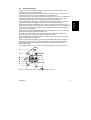
The area where the upper and lower main roller meet is called the “nip”. The upper main
roller can be moved up or down manually, so the nip can be varied to feed materials of
various thicknesses. A mechanical read-out shows the value set.
The nip setting hand wheel also sets the pressure for the laminating process.
The lower main roller is motor driven. The speed can be manually set between zero and a
given maximum value.
Because both rollers are equipped with a heater, heat activated materials can also be
processed with these rollers. Each roller has its own temperature control unit, so top and
bottom roller temperature must be set separately.
In addition to the main rollers a pull roller set is provided to prevent warping of
encapsulation results. (This set is not suited for cold lamination processes.)
An optional cooling device can be installed in front of the pull roller set. When both heaters
are turned on, the cooling device will prevent the pull rollers from warming up too much
and therefore prevents the encapsulation result from showing wrinkles
Five material shaft positions are standard on the machine. Three of these shaft positions
can function as both an unwind or as a wind-up position, which makes the machine more
flexible and enables roll to roll processing for some processes.
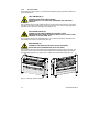
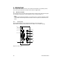
The machine can be divided into an upper and a lower section.
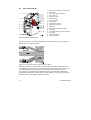
The upper section, above the in-feed table, consists of 3 auto-grip shaft positions and a
splitter bar (idler).
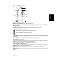
The top shaft position is for unwinding film, the one on the front side for winding e.g. the
release liner. The third shaft position is an unwind/wind-up position, which enables more
flexibility in the use of this section.
The 2 shaft positions in the lower section are both unwind/wind-up positions, which gives
maximum flexibility for this section.
Description
11
English
2.1