1
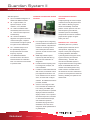
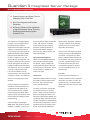
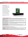
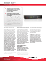
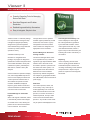
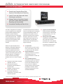
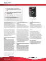
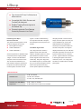
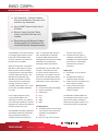
Guardian System II
Return Path Monitoring
■■ Complete Return Alignment, Monitoring
and Ingress Troubleshooting System
■■ Supports Both Field Operations and
Real-time NOC Operations
■■ Hardware, Software Components Easy
to Integrate
■■ Simple to Use
■■ Extremely Cost-Effective in All
Configurations
■■ DSP Technology Captures Fast
Transient Impulse Noise and Ingress
A VoIP Imperative
Guardian System II™ is an integrated
system of hardware and software that
supports all return path maintenance
activities, from installation testing,
to distribution system alignment
and ingress control, to ingress
monitoring and real-time, NOClevel troubleshooting. All elements
of Guardian II are closely linked for
maximum efficiency, flexibility, and
optimum cost-effectiveness. Monitoring
the return band with DSP technology
enables capture of fast transient
impulse noise and ingress, as well
as visibility of interfering signals
beneath service carriers using unique
TraffiControl feature.
Installation
The Guardian RSVP²™ installer’s
return tester has become the industry
standard for preventing return path
installation problems, with many
thousands in daily use. Communicating
with a 9581 SST™ in the head-end, the
RSVP² verifies both the transmission
level from the house and the carrier/
think ahead
www.trilithic.com
(ingress+noise) ratio of the entire path
from home to hub. Fast and very
simple to use, RSVP² remains the
only installation tester with sufficient
measurement range to insure trouble
free return services. An expanded
version of the RSVP², option VP-1, is
also available in the 860 DSP™ signal
analyzer. The VP-1 simultaneously
tests the performance of up to eight
frequencies and assigns to each its
individual pass or fail rating.
Distribution Alignment and Ingress
Control
Working with an 9581 SST in the
hub, the 9580 SSR™ displays errors
in amplifier gain and tilt both as a
graph and as calculated values. The
SSR also displays the return ingress
spectrum, as scanned by the SST,
as an aid for troubleshooting ingress.
SSR functions are also available in the
860 DSP signal analyzer, option SR-1,
with additional capabilities including a
screen that compares the ingress seen
by the SST with the ingress at the field
connection point, in real-time.
1-800-TRILITHIC
Guardian System II
Return Path Monitoring
Diagnostic Operations
Viewer II™ software gives the operator
considerable flexibility in servicing
SNMP traps from 9581 SSTs displaying
spectra for viewing and analysis and
managing the heavy flow of alarm traffic
typical of a busy NOC. Node topology
can be organized by geography,
facilities and services, and even by
maintenance organization. Viewer II
enables the operator to select from a
wide range of resolution bandwidths,
frequency spans, detector types, and
other functions needed for efficient
trouble shooting.
Spectrum Capture Speed:
Rescan rate: all nodes rescanned 40 to
120 times per second
Communications:
Forward data carriers to field units.
Ethernet with ECM communications
option; built-in SNMP agent transmits
up to 8 different trap sets to up to 8
servers running Viewer II or other
management applications.
RSVP² Installer’s Reverse Tester
860 DSPi Signal Analyzer
■■ Multifunction installation, signal
■■
■■
KEY ELEMENTS OF THE GUARDIAN
SYSTEM II
9581 SST Return Path Analyzer
■■ Simple automated tool for insuring
■■
Scans return spectrum, tests ingress
against user defined limits, issues
SNMP traps, provides live analytical
data in several simultaneous formats
to the field and to network operators.
Extremely fast, the 9581 SST: scans
each node in under 100 microseconds
and rescans all nodes up to 120 times
per second; analyzes reverse test
signals from field units and supplies
sweep, ranging, and spectral data
to field technicians; and compresses
spectral data for historical analysis.
The TraffiControl™ function enables
viewing of ingress normally hidden in
upstream traffic.
■■
quality of reverse installations.
Conducts ingress and ranging
level tests on a selected
frequency, gives PASS/FAIL and
measurement data in seconds.
Works with both legacy 9580 SST
and 9581 SST Return Path.
Operating Frequency:
Single frequency: 5 to 42 MHz, settable
at SST in 100 kHz steps
Return Transmit Test Range:
20 to 55 dBmV
Max C/(I+N) Test Range:
Greater than 35 dB
Frequency Range:
0.3 MHz to 65 MHz
■■
DOCSIS modem and VoIP test
suites, including calculated MOS.
With SR-1 option, performs reverse
alignment and troubleshooting
functions; additional display
function showing both local
ingress spectrum and spectrum
downloaded from 9581 SST.
With FS-1 option, performs
forward sweep as part of the
SpeedSweep™ system in
addition to reverse alignment and
troubleshooting functions of option
SR-1.
With option VP-1, performs the
functions of the RSVP² installer’s
reverse tester (above) on up to 8
frequencies.
Standard Functions:
■■ Channel levels and scan
■■ Reverse spectrum scan
■■ PC substitution
■■ Modem performance
■■ MER/BER
■■ VoIP test suite (including up and
downstream latency, jitter, lost and
discarded packets)
■■ Computed values of MOS (mean
opinion score)
■■ Auto tests (FCC Part 76 and userdefined tests)
Number of Test Points:
Up to 16 connections per 9581 SST
think ahead
■■
analysis, and distribution
maintenance analyzer from 5 to
1,000 MHz.
The basic 860 DSPi includes
www.trilithic.com
■■ Data logging
■■ Text browser
1-800-TRILITHIC
Guardian System II
Return Path Monitoring
860 DSPi Options:
■■ QA-2: Constellation diagrams: 16
QAM to 256 QAM and QPSK.
■■ SA-1: High-resolution, fullspectrum analysis: 10 kHz
resolution, 5 to 1,000 MHz.
■■ VP-1: Return installation tests:
Automatically tests launch Level,
C/I. Tests 8 reverse frequencies
simultaneously.
■■ SR-1: Reverse distribution
alignment and ingress tests: Plots
reverse tilt and gain, compares
local and head-end ingress spectra
for ingress source identification.
■■ FS-1: Forward sweep: Part of
the SpeedSweep System™
that provides tests for forward
frequency response.
■■ CI-3: MODEM substitution:
Provides access to the internal
DOCSIS modem for substitution
tests or for external communication
in upstream traffic.
GUARDIAN II INTEGRATED SERVER
PACKAGE
■■ Pre-configured server, integrating
■■
■■
■■
■■
powerful software and hardware to
provide a tailored, comprehensive
solution for monitoring reverse
and forward path HFC network
spectrum, as well as various other
parameters.
SNMP trap handlers capture
traps sent by 9581 SST R4, log
them and send notification as
designated.
Includes extensive reporting tools
for management, analysis, and
node certification.
In addition to Microsoft® 2003 and
SQL servers, the hardware comes
preconfigured with Viewer II v2.6
server software and one onboard
client, as well as SST Configure
software. Six additional clients are
provided, standard.
Viewer II v2.6 configures nodes
to be monitored and viewed from
tree or listing, sets RBW, span,
and other parameters for spectrum
displayed; allows simultaneous
display of alarm or “live” spectrum
with historical spectrum, limit lines
or minimum/maximum/average,
and TraffiControl spectrum;
assembles trap logs and other
databases in form that can be
analyzed in Excel spreadsheets or
Crystal Reports.
ADIA INTEGRATED SERVER
PACKAGE
Analytical package for off-line analysis
of historical reverse path performance
data. Ideal for detecting long-term
trends and availability of selected
portions of return spectrum over time.
ADIA analyzes ingress histories,
calculates spectrum unavailability,
and presents the results as “waterfall”
graphs and line graphs of ingress
activity over time.
Bringing it all Together
Guardian System II is a powerful,
flexible system of field and central
office products, supporting all
aspects of return path management
including installation, distribution
system alignment and ingress control,
ingress monitoring, and real-time
troubleshooting. The 9581 SST,
the hub of the Guardian System II,
supports field technicians using Trilithic
RSVP² or 860 DSPi field units and
network-connected engineers using
Trilithic Viewer II and ADIA software.
All elements of the return maintenance
process are closely linked for maximum
efficiency, flexibility, and optimum costeffectiveness.
071509-REV1
think ahead
www.trilithic.com
1-800-TRILITHIC
Guardian II Integrated Server Package
Reverse Band Monitoring Software
■■ Powerful Analysis and Report Tools for
Managing Return Path Data
■■ Real-Time Diagnosis and Problem
Resolution
■■ All Server Software is Pre-Installed on
a High Performance Server, Ensuring
Reliability and Minimizing System
Activation Time
The Guardian II™ Integrated Server
live-view spectrum display for selected
display severity thresholds. Individual
Package is a pre-configured server,
integrating powerful software
applications and hardware to provide
a tailored, comprehensive solution
for monitoring reverse path spectrum.
SNMP trap handlers capture SNMP
traps sent by the 9581 SST™ R4s,
log them to Viewer II™ v2.6, and
send notification as designated. The
package includes extensive reporting
tools for management and analysis.
In addition to Microsoft® 2003 Server
and SQL Server, the server hardware
comes preconfigured with Viewer
II v2.6 server software, and one
onboard Viewer II v2.6 client and SST
Configure™ software. Six additional
Viewer II v2.6 clients are provided
standard.
nodes. With Viewer II an operator
controls 9581 SST R4s in hubs or
head-ends, permitting selection of
resolution bandwidths, displayed
frequency span, detector modes, and
other characteristics.
or groups of alarms can be manually
cleared (or the source of the alarms
temporarily disconnected).
Viewer II viewing and management
software for the Guardian System II
is designed to make optimum use
of the broad feature sets of Trilithic
monitoring equipment (9581 SST™
release 4 return path analyzer), and is
used for spectrum management and
troubleshooting.
Viewer II displays and manages
SNMP traps, with extensive reporting
capability. In addition, it serves as a
think ahead
www.trilithic.com
Ingress Alarm Management
Viewer II receives SNMP alarms from
9581 SST R4s located throughout
the network. Viewer II displays the
incoming 9581 SST alarms with colorcoded severity in a tabular list. Alarms
are also shown in a similarly color
coded “tree” graph.
Tabular View
The tabular display presents a running
list of alarms, itemized with the alarm
time, type, origin (extended node
name), and alarm severity.
For his/her convenience, the operator
can sort the alarms by any of these
criteria. Viewer II includes a full set of
tools for managing alarm traffic. The
alarm list is automatically updated, with
new listings added whenever the status
of nodes is upgraded or downgraded by
new traps sent by 9581 SSTs. Viewer II
also allows the user to manage “alarm
storms” by temporarily adjusting the
1-800-TRILITHIC
Alarms can be color tagged to indicate
that they have been acknowledged but
not cleared. The operator can attach
timers to individual alarms that will call
for his attention if an alarm persists for
more than a specified length of time.
As an aid in determining the cause
of the ingress outbreak, the operator
can view recent alarm history of the
selected node.
Tree View
The tree view presents alarms in a
manner that makes it easy to determine
the location of an alarm or node in the
network topology. As with the tabular
display, alarming nodes are color coded
by severity.
Guardian II Integrated Server Package
Reverse Band Monitoring Software
The tree view also simplifies navigation,
allowing an operator to display a
selected node, live, by clicking its
symbol on the tree. Tree view can be
expanded or collapsed as desired,
with the alarm color codes following.
Right clicking on either a list item or
tree branch/leaf presents the operator
with additional display and navigation
options. The operator can reconfigure
the relationships in the tree to show
associations by topology, such as all
nodes connected to the same CMTS
blade or served by the same 9581 SST,
or associated with a particular service
area within the region served by the
NOC.
Live View Function
The operator can bring up spectrum
live views of one or more nodes by right
clicking on a node in the tabular alarm
list or in a tree view. Each live view
node spectrum is updated every few
hundred milliseconds, and the running
maximum, minimum, and average
spectra from the moment the selected
spectrum was first displayed. Markers
simplify accurate measurement of
ingress frequencies and amplitudes.
Each live view includes the node name,
so several live views can be open at a
time, either tiled or cascaded, without
confusion. Tiled or cascaded views can
be parked at convenient spots on the
status monitoring screen and expanded
to full live view size as needed. Any
live view can be saved with all of its
settings, markers values, extended
node name, and a user-entered
comment.
The operator can adjust the settings of
a live view spectrum to fit his needs,
selecting frequency spans by entering
think ahead
www.trilithic.com
either start/stop frequencies or center
frequency and span, or resolution
bandwidths of 30 kHz, 100kHz, 300
kHz, 1 MHz, or a special 375 KHz RBW
fast transient capture mode.
used in the monitoring mode, but the
user can change the organization. This
enables users with different areas of
responsibility to see data that pertains
specifically to them.
The operator may select from several
detector modes, including peak,
average (with control over how many
spectra are averaged), minimum hold,
and maximum hold. A special detector
function, TraffiControl™, is available
in resolution bandwidths of 375 kHz.
TraffiControl removes all TDMA traffic
from the return spectrum, making
it easier to detect ingress normally
obscured by return services. Note that
TraffiControl must be configured in
each 9581 SST using SST Configure
software.
For more detailed investigation, the
user can select any subset of the tree
using a drill-down feature for analysis or
troubleshooting.
All live views can be printed. The
printout includes report type, extended
node ID, time and/or time frame, and
values of markers (there are two) where
applicable. The operator can add a
comment to the printout.
Recent History View Function
As an aid to troubleshooting, the
operator can bring up summaries of
recent spectra for any selected node.
This function provides 15 records, each
representing one minute, altogether
spanning the most recent 15 minutes.
Reports
Viewer II v2.6 has enhanced reporting
capability that enables a system health
overview and the ability to drill down for
more detailed information.
Organization trees can be used to
group nodes as desired (reporting
area). These trees may be the same
1-800-TRILITHIC
To determine if ingress is time/date
specific, the user can set a time or time
interval of interest to further enhance
troubleshooting ability.
The user can select a desired alarm
threshold(s) to determine which nodes
have the highest number of alarm
incidents, or select a percentage of
node unavailability to include the
duration of the incidents in the analysis.
The database allows user definable
attribute fields to be attached to a node
and later used in reports. A report can
be sorted by these attributes. The
number of VoIP subscribers for each
node can be added, for instance.
To concentrate troubleshooting efforts
on worst cases, or those affecting the
highest number of subscribers, the
user can restrict the report to a certain
number of nodes at each level (top 10,
for example).
The user can view report data in tabular
form, and in some cases the data can
be graphed to make analysis easier.
User defined reports can be saved.
Reports can be scheduled to run at
night, or at low traffic times to manage
computer resources.
Guardian II Integrated Server Package
Reverse Band Monitoring Software
Bringing It All Together
The Guardian System II is a powerful,
flexible system of field and central
office products supporting all aspects
of return path management, including
installation, distribution system
alignment and ingress control,
ingress monitoring, and real-time
troubleshooting. The 9581 SST, the
hub of the Guardian System II, supports
field technicians using Trilithic RSVP²™
and 860 DSP™ field units and networkconnected engineers using Trilithic
Viewer II and ADIA™ software. All
elements of the return maintenance
process are closely linked for maximum
efficiency, flexibility and optimum cost
effectiveness.
INTEGRATED SOFTWARE SPECIFICATIONS
Microsoft Windows® 2003
Server
A comprehensive, integrated, and dependable server platform designed to reduce costs
and increase the efficiency and effectiveness of computing operations.
Microsoft SQL® Server
More than a relational database management system; it is a complete database and
analysis product that meets the scalability and reliability requirements of the most
demanding enterprises.
Viewer II Server/Client
Viewing and management software designed to make optimum use of the broad feature
sets of Trilithic’s monitoring equipment (9581 SST return path analyzer), and is used for
spectrum management and troubleshooting.
SST Configure software
Configures 9581 SST for network access, monitoring and field unit support.
HARDWARE SPECIFICATIONS
Specially-Configured Dell PowerEdge® 2U Rack Mount Server
Storage
Supports 1 year of data for 3,000 nodes
Warranty
Next business day, parts and labor with on-site response – 3 years (from Dell)
A second power supply is available from Dell to provide redundancy and extra reliability. A backup storage system is recommended for prevention of data loss.
think ahead
www.trilithic.com
1-800-TRILITHIC
Guardian II Integrated Server Package
Reverse Band Monitoring Software
ORDERING INFORMATION
Guardian II Integrated Server Package
Part Number
2011009100
Description
Preconfigured server including Viewer II, one onboard Viewer II client plus six additional
Viewer II clients, and SST Configure software
Optional Accessories
One Additional Viewer II
Client License
Six Additional Viewer II
Client Licenses
P/N 0930098100
P/N 0930098106
012609-REV1
think ahead
www.trilithic.com
1-800-TRILITHIC
9581 SST
Return Path Analyzer
■■ Catch “Bursty” Ingress and Impulse
Noise Interference to Voice Services
with Extremely High Spectrum
Acquisition Speed
■■ Manage Service Quality Efficiently
with 24/7 Monitoring and Configurable
SNMP Alarms
■■ Align and Troubleshoot Reverse Path
Quickly and Easily, and Cost-Effectively
Consolidate Installation and Network
Maintenance Support Equipment in the
Head-End
■■ Scalable and Cost-Effective in Every
Configuration
The 9581 SST™ is the hub of the
Guardian System II™ for return path
maintenance; providing installation,
reverse sweep, and ingress spectrum
information to field technicians using
Trilithic’s field units. When used in
a Guardian System II, the 9581 SST
shares spectrum information with the
monitoring facility and the field units,
speeding up problem identification and
shortening repair times. The 9581 SST
monitors the return band, generates
SNMP traps, and relays monitored
data to NOCs and designated network
engineers. Extremely flexible, each
SST supports up to twelve distribution
technicians and a virtually unlimited
number of installers. It can provide
live spectrum information and recent
historical data to as many as eight
independent monitoring sites, each
using its own SNMP trap criteria. Traps
sent to each of these sites can be
configured for different ingress severity
alarm limits and persistence.
think ahead
www.trilithic.com
Ability to Capture all Types of Ingress
Cutting-edge DSP technology gives
the 9581 SST unmatched power for
capturing all types of ingress, including
the short bursts that degrade VoIP
services. Up to 100 times faster than
analog-based analyzers, the 9581
SST captures and analyzes the entire
spectrum of all connected nodes in
microseconds and re-scans them up
to 120 times per second. Thanks to
the 9581 SST’s unmatched scanning
speed and high re-scan rate, the NOC
operator or field technician never
misses an ingress outbreak capable of
disrupting return services.
Features a Wide Selection of
Operating Modes
A wide selection of operating modes
makes the 9581 SST a highly versatile
return path troubleshooting aid.
Through the Viewer II™ software,
the operator can view node spectrum
information at resolutions from 30 kHz
to 3 MHz to facilitate troubleshooting.
1-800-TRILITHIC
The operator can also select averaging
and continuously running maximum
and minimum functions to diagnose
immediate problems and long-term
performance issues.
TraffiControl™, a data processing
mode unique to the 9581 SST, lets
the operator analyze ingress hidden
inside occupied frequency bands.
TraffiControl automatically removes
all legitimate TDMA signals from the
displayed spectrum, leaving an easily
analyzed spectrum composed solely of
noise and ingress.
9581 SST
Return Path Analyzer
Versatile, Flexible, and Scalable
The 9581 SST simultaneously
supports:
■■ Installation tests
■■ Distribution sweep and
maintenance
■■ Return path performance
monitoring
Fast and Accurate Installations
The RSVP² Installer’s return tester and
860 DSPi™ field analyzer with the VP-1
option analyze data from the 9581 SST
to evaluate the reverse power level
and C/(N+I) from the subscriber to the
head-end.
Each 9581 SST can:
■■ Support up to 16 individual nodes
■■ Support up to 12 distribution
technicians
■■ Support dozens of installers
■■ Send traps and live spectrum data
to as many as eight server sites
Efficient Distribution Maintenance
The 9581 SST transmits sweep and
return spectrum information to 860
DSP™ Field Analyzers and RSVP²™
installation testers, updating all field
displays every 0.8 seconds regardless
of the number of instruments being
supported.
Superior Return Monitoring
When used with Viewer II monitoring
software, the 9581 SST can dispatch
traps to as many as eight servers,
each provided with its own SNMP
trap criteria. Each client user has
independent selection of display
resolution and may choose any
available detector settings without
interference to other users or loss of
speed.
The Guardian System II
The Guardian System II is a powerful,
flexible system of field and central
office products, supporting all
aspects of return path management,
including installation, distribution
system alignment, ingress control,
ingress monitoring, and real-time
troubleshooting. All elements of the
return maintenance process are closely
linked for maximum efficiency, flexibility
and optimum cost-effectiveness.
General Specifications
Standard Connection
2 test ports
Optional Connections
Add 1 TPM-8 module: 9 test points
Add 2 TPM-8 modules: 16 test points
Each test point is analyzed individually
Functions Simultaneously
Supported
Reverse sweep, working with 9580 SSR field units or 860 DSP signal analyzer with
Option SR-1
Reverse installation testing, working with RSVP² installer’s reverse tester or 860 DSP
signal analyzer with option VP-1
Reverse path ingress monitoring with SNMP alarms compatible with Viewer II software
Measurement Refresh
Speed
Field equipment: Every 0.8 seconds
Monitoring and alarming: Every 0.4 seconds
Live-viewing functions: Every 0.4 seconds
think ahead
www.trilithic.com
1-800-TRILITHIC
9581 SST
Return Path Analyzer
Spectrum Data Resolution (RBW)
Network Applications
30 kHz, 100 kHz, 300 kHz, 375 kHz, 3 MHz
Field Applications
375 kHz
Transient Troubleshooter
Mode
300 kHz at high scan rate
Display Range
50 dB dynamic range, 1 dB measurement resolution
Level Accuracy
±1 dB
Spectrum Processing Modes (Available simultaneously)
Peak Mode
Single spectrum comprised of the peak values of 16 to 32 spectrum scans collected
during the previous 0.4 seconds
AVG Mode
Single spectrum averaging the 16 the 32 spectrum scans collected during the previous
0.4 seconds
TraffiControl Mode
Processes return spectra to remove all TDMA traffic to enhance ingress detection
Updates every 0.4 seconds
Spectrum Scan Rate
ENM Mode
Supports both network and field applications: scans all test points at rate of 40 scans
per second
SFM Mode
Supports only transient monitoring and analysis functions: scans all test points at rate
of 120 scans per second
Field Unit Support
Field Functions Supported
think ahead
Spectrum view: 0.3 to 65 MHz
Current node is automatically selected or user may select other nodes supported by
the same SST.
Sweep: 0.3 to 65 MHz
Up to 12 field units independently supported per SST.
Ranging test for installation verification. Typically supports 50 or more RSVP² reverse
installer’s tester or 860 DSP with option VP-1, per SST.
www.trilithic.com
1-800-TRILITHIC
9581 SST
Return Path Analyzer
Field Communications
Data Carrier
1 telemetry carrier for each 8 test points
Data Carrier Frequency Set
Ranges
50.00 to 53.75 MHz and 70.00 to 75.75
MHz; or 80.5 to 92 MHz
Setting range is specified at time of order
Data Carrier Frequency
Resolution
Center frequency is user-settable in 50 kHz
steps
Data Carrier Occupied
Bandwidth
150 kHz at -20 dB
475 kHz at -60 dB
Network Support
Communications
10 Mbit/second Ethernet LAN connection
(requires optional communications
interface)
9581 SST functions as mini-server
supporting up to 6 simultaneous users,
each with a unique user name
Data Available per Test
Point
Live spectrum scans, all detector modes
Last ingress-affected spectrum
Last test results versus 4 amplitude limit
sets, user-settable persistence threshold
Running, long-term maximum and
minimum spectra (restartable by user)
Peak, minimum, and average spectrum
data compressions for last 30 minutes
Includes the following:
SST Configure™ software
P/N 0930105000
ADIA™ software
P/N 2011093100
Guardian System II software
P/N 2011009100
A/C power line
User’s manual
Optional Accessories:
I/O-7 TPX data cable
P/N 2071112000
I/O-10 NCM-4 data cable
P/N 2071119001
Mechanical, Miscellaneous
SST Display Panel
1.5” x 2.75” backlit LCD
(38mm x 70mm)
Controls
Tactile key pad
Dimensions (H x W x D)
3.5” x 17” x 12.3”
(89mm x 432mm x 312mm)
Weight
7 lbs (3.18 Kg)
Power
95 to 240 VAC, 50 to 60 Hz
012309-REV1
think ahead
www.trilithic.com
1-800-TRILITHIC
Viewer II
Return Path Management Software
■■ Powerful Operating Tools for Managing
Return Path Data
■■ Real-time Diagnosis and Problem
Resolution
■■ Detailed Logs and Activity Summaries
■■ Easy to Integrate, Simple to Use
Trilithic’s Viewer II™ software package
is a comprehensive viewing and trap
management program specifically
designed for ingress management
and troubleshooting in large territories
overseen by a NOC (network
operations center).
Available exclusively on the
Guardian II™ integrated server
package, the program is designed to
optimize and enhance the performance
of the Trilithic Guardian II return path
maintenance system, particularly the
9581 SST™, release 4 return path
analyzer.
Viewer II allows the operator to display,
sort, and manage SNMP traps and to
see a live-view display that shows the
current spectra of selected nodes. It
also enables the operator to select
resolution bandwidths, displayed
frequency span, detector modes and
other characteristics for 9581 SST-R4
units in the hubs or head-ends.
Incident Manager to Track Node
Ingress
When node ingress is detected, Viewer
II automatically creates and manages
an incident for the node, allowing the
problem to be monitored and tracked
until it is resolved. The incident
think ahead
www.trilithic.com
manager allows users to prioritize
and filter ingress problems by several
criteria and, when used in a group
management environment, allows
each incident to be assigned to the
appropriate user for resolution.
Element Manager for Structured
Viewing of Nodes
The element manager allows nodes
to be organized into any number of
logical tree-type representations called
element views. Elements can be
structured to provide a quick view into
the status of the entire system, or of
selected parts of the cable network.
Element trees can be created to
represent any desired configuration.
For example: by geographical location,
hub, CMTS blade, service technician or
power supply.
Node View
The current spectrum, status, and
recent history of any node may be
viewed graphically in the node view.
Node view includes the current node
spectrum, more than 30 minutes of
historical spectrum, and up to 1000
of the most recent threshold alarm
spectrum. Any number of node views
may be opened and displayed at once.
1-800-TRILITHIC
Chronological Event History List
Viewer II displays a chronological
list of all ingress alarms generated
by the 9581 SST hardware. When
node ingress levels reach any of the
user-defined thresholds, Viewer II
logs an entry into the event history list
indicating the location and severity of
the violation.
Reporting
Viewer II reporting services allow
users to quickly generate detailed or
summarized reports to assist in the
recording and trending of node histories
and performance. Reports may be
printed or exported to several popular
file formats.
Viewer II
Return Path Management Software
Specifications
Integrated Software Specifications
Microsoft Windows® 2003
Server
A comprehensive, integrated, and dependable server platform designed to reduce
costs and increase the efficiency and effectiveness of computing operations.
Microsoft SQL® Server
More than a relational database management system; it is a complete database and
analysis product that meets the scalability and reliability requirements of the most
demanding enterprises.
Viewer II Server/Client
Viewing and management software designed to make optimum use of the broad
feature sets of Trilithic monitoring equipment (9581 SST-R4 return path analyzer), and
is used for spectrum management and troubleshooting.
SST Configure Software
Configures 9581 SST for network access, monitoring and field unit support.
Hardware Specifications - Specially Configured Dell PowerEdge® 2U Rack Mount Server
Storage
Supports one year of data for 3,000 nodes
Warranty
Next business day, parts and labor
On-site response – 3 years (from Dell)
Ordering Information - Guardian II Integrated Server Package
Part Number
2011009100
Includes the Following
Optional Accessories
Pre-configured server including Viewer II, one onboard Viewer II client plus six
additional Viewer II clients, and SST Configure software
Optional Accessories
One Additional Viewer II
Client License
P/N 0930098100
Six Additional Viewer II
Client Licenses
P/N 0930098106
012909-REV1
think ahead
www.trilithic.com
1-800-TRILITHIC
ADIA
INTEGRATED SERVER PACKAGE
Historical Data Analysis Software
■■ Powerful and Complete Return Path
Spectrum Data Analysis and Reporting
■■ Identify Trends with Measurable Node
Performance and History
■■ Manage Technical Operations Support
with Clear Problem Node Identification,
Reporting and Accountability
■■ Unmatched Flexibility and Ease of Use
The ADIA™ integrated server package
is a pre-configured server, integrating
powerful software applications and
hardware to provide a tailored,
comprehensive solution for managing
return path spectrum data. In addition
to Microsoft® 2003 Server and SQL
Server, the server hardware comes
preconfigured with ADIA server
software.
The ADIA analysis server provides all
of the recommended tools, as specified
in the NCTA Standard Practices¹, for
evaluating a return path in terms of
performance to limits and for tracking
changes in performance over time.
Using Trilithic’s ADIA engineers can
quickly determine, over specified
intervals within selectable frequency
ranges and bands:
ADIA is an ingress analysis server
application, specifically designed for
convenient and efficient historical
analysis of upstream performance
over periods as long as a year. ADIA
collects summarized ingress data from
Guardian System II™ installations
in hubs and head-end, building a
database that can be used for analysis
of:
■■ Live Spectrum
■■ Persistence and severity of ingress
outbreaks over time
■■ Recurring and long-term
■■
■■
intermittent ingress problems on
selected nodes
Suitability of frequencies and
bands to carry services
The statistical likelihood of
disturbances in any portion of the
measured spectrum
■■
■■
Shows up to four curves at a time
of the current activity on the node
or nodes that you have selected.
Historical Spectrum
Displays the maximum, minimum
and average levels for all
frequencies between 375 kHz and
65 MHz.
Over Limit By Frequency
Calculates the DISP as the percent
of threshold violations for each of
the four user thresholds for each
time increment. In addition to
specific frequency discrete ingress
probability, this function allows
analysis to be performed in userselectable bandwidths.
¹ NCTA recommended practices for cable television systems, supplement on upstream transport issues, 10/97
think ahead
www.trilithic.com
1-800-TRILITHIC
■■ Ingress Threshold Probability
■■
Plots percentage unavailability
versus frequency and threshold
for each frequency over a user
specified time period.
Average Over Limit (ADISP)
Calculates the average probability
that a node will exceed its
thresholds over a user-specified
time interval. The ADISP is useful
as a “figure of merit” test for a
node’s overall performance.
ADIA
INTEGRATED SERVER PACKAGE
Historical Data Analysis Software
Integrated Software Specifications
Microsoft
Windows® 2003
Server
A comprehensive, integrated,
and dependable server
platform designed to reduce
costs and increase the
efficiency and effectiveness of
computing operations.
Microsoft SQL®
Server
More than a relational
database management
system; it is a complete
database and analysis product
that meets the scalability and
reliability requirements of the
most demanding enterprises.
ADIA Software
Integrating powerful software
and hardware to provide
tailored, comprehensive
solution for managing return
path spectrum data.
Over Limit by Frequency analyzes all data points during a specified time
interval and for a specified frequency range. It displays the percentage of
time that some frequency experienced ingress activity above your specified
thresholds.
HARDWARE SPECIFICATIONS
Specially-Configured Dell PowerEdge® 2U Rack Mount
Server
Average Over Limit averages all data points during the specified interval
and displays the percentage of time during that given interval that the four
thresholds were broken.
Storage
Supports one year of data for
3,000 nodes
Warranty
Next business day, parts and
labor
On-site response: 3 years
(from Dell)
A second power supply is available from Dell to provide redundancy and
extra reliability. A backup storage system is recommended for prevention of
data loss.
ORDERING INFORMATION
ADIA Integrated Server Package
Part Number
2011093100
Includes the
following optional
accessories
Preconfigured server including
ADIA history analysis
6 additional passwords
Ingress Threshold Probability shows the percentage of time when a node
crossed a threshold, by frequency.
012609-REV1
think ahead
www.trilithic.com
1-800-TRILITHIC
8300 FST
Forward Speed Sweep Transmitter
■■ Forward SpeedSweep Transmitter
■■ Fast Sweep Update, Even with High
Concentration of Digital Channels
■■ Measures Active System Carriers Plus
Injected Sweep to Obtain High Sweep
Frequency Resolution, Especially
Digital Carriers
■■ Complete Plant Maintenance Solution
for 860 Field Analyzers
■■ Comprehensive Best-in-Class
Measurement Functionality in a
Sweep-Capable Meter
The 8300 FST™ Forward SpeedSweep
Transmitter is an essential part of the
system for comprehensive sweep
capability in the 860 DSP™ field
analyzer family.
The instrument is rack-mounted in the
head-end, and generates a sweep
that steps around system carriers to
avoid interference, filling in vacant
spectrum areas for a complete view of
the network frequency response. The
860 DSP (with FS-1 option) receives
the sweep, and based on the measured
sweep and system carrier levels, plots
the frequency response. The response
is compared to a stored reference to
provide a difference display. With the
goal of the network design being unity
gain from amplifier output to amplifier
output, the ideal response will be as flat
as possible. The sweep test provides
a measure of the RF transmission
characteristics of the network between
the transmitter and the receiver, and is
used as a day-to-day maintenance tool
for the RF portion of the HFC network.
think ahead
www.trilithic.com
Trilithic’s SpeedSweep solution
includes:
■■ The 8300 FST that generates a
sweep stimulus for the downstream
measurement.
■■ The 860 DSP with a sweep option
(FR-1) that receives the forward
sweep and transmits reverse
sweep signals for upstream
measurements.
■■ The 9581 RSA™ (a 9581 SST™
with a narrowed sweep/alignment
application orientation) to receive
the upstream sweep signal
generated by the 860 DSP or
RSVP²™ field unit, and then relay
the measurement results back to
the field unit generating the signal.
The 8300 FST generates a sweep
that is received by an 860 DSP (with
FR-1 option). This option enables
the technician to test both forward
and return frequency response. The
transmitter is part of the “distribution”
products category and is considered an
essential tool for plant maintenance.
1-800-TRILITHIC
The transmitter will be located in the
headend, and combined with other
network signals. The technician will
establish a test normalization reference
response at the node or at a sweep
test point in the head-end after the
combining network, designed to match
levels at amplifier/node output test
points.
8300 FST
Forward Speed Sweep Transmitter
Specifications
RF Specifications
Frequency Range
47 to 1,000 MHz; 250 kHz resolution
RF Output Level
Rear panel adjustment, 46 dBmV to 58 dBmV
(typical)
Accuracy/Stability
±5 kHz
Spurious Output
>60 dB (typical)
Out-of-Band C/N Ratio
>80 dB
Includes the following:
Rack-mounted 6 MHz forward sweep
transmitter
External Features
Front Panel Controls
Reset button
Front Panel LEDs
RF on, power/error
Rear Panel Connectors,
Controls
F-type connectors for RF output / RF test point
Serial data connector for setup
RJ-45 Ethernet connector
RF output level control
General
Power Supply
Universal 90 VAC to 240 VAC, 50 to 60 Hz with
IEC 320 power connector
Power Consumption
<30 Watts
Physical Size
(H x W x D)
1.75” x 19” x 12” (44mm x 483mm x 305mm)
1U rack mount
Weight
10 lbs (4536 g)
010709-REV1
think ahead
www.trilithic.com
1-800-TRILITHIC
RSVP²
Installer’s Reverse Path Tester
■■ Eliminates Callback Truck Rolls By
Ensuring Installation Quality on the First
Visit
■■ Verifies Operation Headroom for Critical
Digital Services
■■ Quick, Simple, Automated Testing with
Pass/Fail Results
■■ Small, Rugged, Lightweight and
Simple-to-Use
The Guardian RSVP²™ ensures return
quality where it is most critical – the
subscriber’s installation. Most return
path problems begin in the subscriber’s
home. Errors in installation, defective
cabling, or incorrectly installed or loose
hardware can all disrupt return path
communications or allow ingress to
enter the cable system. The RSVP²
tests the key return parameters that
verify the installation is error-free and
ready for the demands of VOD, VoIP
and HSD return services.
Return Path Tests: Quick, Sure and
Easy
Pressing the “Test” button opens
communications with a Guardian
9581 SST™ Reverse Path Analyzer
in the hub or head-end. Automatic
measurements quickly measure the
required upstream transmit level
and compute the carrier/(noise +
ingress) ratio for the path between
the subscriber and the 9581 SST.
The RSVP² compares the results
of both tests to user-settable limits
and in seconds displays a simple,
unambiguous “pass” or “fail.” The
installer can also view the actual
measurement data as an aid to
troubleshooting.
think ahead
www.trilithic.com
The Importance of Measurement
Range
Only the RSVP² / 9581 SST
combination provides the ingress
measurement range needed to ensure
reliable HSD, VOD, and VoIP services
under all conditions. Complaint-free
return services require a C/(N+I) ratio
of better than 25 dB in all conditions.
Installations done during the workday
must include sufficient ingress margin
to meet mid-evening conditions when
the ingress can be 6 dB worse. Of all
available return path measurement
systems, only the Guardian RSVP²
tests C/(N+I) with the range needed to
ensure trouble-free service. And it does
it with a simple Pass/Fail test that can
Fast Return Path Performance
Testing
The RSVP² performs measurements
and analysis in seconds. Operation is
automatic. The installer simply presses
the START button and the RSVP² does
the rest.
be performed in seconds.
The RSVP² is small, rugged, and very
inexpensive, making it ideal for the
installer’s tasks and environment.
Built-in Test Generator for Identifying
Drops
The RSVP² includes a tone modulated
signal source for identifying cables in
MDUs and other installations. Output
is settable in both frequency and level.
The source may be used continuously
for up to five hours on a single charge.
1-800-TRILITHIC
Consistent Measurements
The RSVP² evaluates upstream
level and C/(N+I) measurements
against settable limits and delivers an
unambiguous result. Using the ConfigR
Setup™ application, an operator can
pre-program the operating parameters
to ensure consistent installation quality.
Very Cost effective
RSVP²
Installer’s Reverse Path Tester
The Guardian System II™
The Guardian System II is a powerful,
flexible system of field and central
office products supporting all
aspects of return path management,
including installation, distribution
system alignment, ingress control,
ingress monitoring, and real-time
troubleshooting. The 9581 SST, the
hub of the system, supports field
technicians using the RSVP² and
860 DSPi™ field units and network
engineers using the Viewer II™ server.
All elements of the return maintenance
process are closely linked for maximum
efficiency, flexibility, and optimum cost
effectiveness.
Includes the following:
50 to 53.75 MHz / 70 to 75.75 MHz
reverse path tester (P/N 2010814010)
or 80.5 to 92 MHz reverse path tester
(P/N 2010814011)
CC-15 padded carrying case
P/N 2130673000
Battery charger
P/N 0610150000
User’s manual on CD
Specifications
Test Functions
Transmit Level
20 to 55 dBmV
Return C/(N+I) Ratio
≥35 dB for ≥0 dBmV input to SST
Output Test Signals
Test Mode
Used in transmit level test
Single frequency 5 to 42 MHz, automatically
set by transmission from 9580 or 9581 SST
Source Mode
Used with an SLM to ring out cabling
5 to 42 MHz, 20 to 55 dBmV, user-settable
CW, tone and channel tagged output
Mode Transmit Level
Accuracy (All Modes)
±1.5 dB @ -18° to +55° C (0° to 131° F)
Data Carrier Frequency
Choose from: 50.00 to 53.75 or 70.00 to
75.75 MHz, user-settable
Optional: 80.5 to 92 MHz
Data Carrier Receive Range
-15 to +20 dBmV
Display
4 digit LED with annunciators
Charger
115 VAC charger
Charge Time
14 hours, maximum
Operating Temperature
-18° to +55° C (0° to 131° F)
Dimensions
(H x W x D)
4.0” x 5.0” x 1.25”
(102mm x 127mm x 32mm)
Weight
1 lb (454 g)
Optional accessories:
ConfigR software with I/O-6 data cable
P/N 0930018000
F-type push-on adaptors
P/N 0200622000
I/O-6 data cable
P/N 2071082000
I/O-15 precision test cable
P/N 2071527048
CC-15 padded cloth carrying case
P/N 2130673000
011409-REV1
think ahead
www.trilithic.com
1-800-TRILITHIC
I-Stop
Reverse Test Probe
■■ Taps Unused KS Ports For Bidirectional
Measurements
■■ Compatible With SLMs, Reverse and
Forward Path Analyzers
■■ Enables Tracking Reverse Ingress to
the Nearest Tap
■■ Protects Instruments From Damage
Caused by Excessive Line Power
Introducing the I-Stop™
Reverse Test Probe
The I-Stop reverse test probe is a test
accessory designed for use with:
■■ Most signal level meters
■■ Trilithic’s 8821Q-R™
■■ Trilithic’s 860 DSP™
Screw the probe into a distribution tap’s
unused KS port and a spring-loaded
“stinger” connects a 20 dB resistive
test point circuit to the seizure screw.
The connection is bidirectional, so
that an SLM or analyzer connected to
the probe can measure forward and
reverse signals, as well as reverse
ingress. A built-in AC/DC blocking
circuit protects the SLM or analyzer
from damage from online power up to
90 Volts.
Track Down Ingress Fast
The I-Stop probe also contains a
patented circuit that is used with
Trilithic’s Guardian System II™ return
path maintenance system to track
reverse ingress sources down to the
nearest tap. Using the I-Stop probe,
the Guardian System II, and this simple
test, you can locate all ingress sources
down to the tap without removing
reverse pads or diplexers and without
disrupting forward or reverse service.
Simply screw the probe into a KS port
on the distribution tap, connect the
9580 SSR field unit or 860 DSP to
the test port, then press the button on
the side of the probe. If the ingress
displayed decreases by 4 to 6 dB when
the button is pressed, the source of the
ingress is farther from the node than
you are. Ingress that doesn’t decrease
is entering the system nearer to the
node than you are. The I-Stop probe
has little or no visible effect on forward
path signals.
Specifications
Insertion Loss
<1 dB, 5 to 50 MHz
<3.5 dB, 50 to 750 MHz
<1.5 dB, in any 150 MHz span
Insertion Loss with Button
Depressed
≥5 dB, ≤ 8 dB, 5 to 30 MHz
≤1 dB insertion loss increase, 54 to 750 MHz
011409-REV1
think ahead
www.trilithic.com
1-800-TRILITHIC
860 DSPh
Remote Head-End Analyzer
■■ 24/7 Monitoring – Catches Problems
Early by Automatically Scanning Levels
and other Key Parameters
■■ Issues SNMP Traps to Notify User of
Problems
■■ Remote Control Lets User Take a
Closer Look Without Driving to the
Location
■■ Remote Access with Browser Enables
Viewing Head-End or Distribution Hub
Levels with Browser-Equipped Analyzer
The 860 DSPh™ is the ideal instrument
for managing signal quality in remote
head-ends or other facilities where
access is restricted or local technical
personnel are not available.
Based on the powerful, cost-effective
860 DSPi™ cable analyzer, the 860
DSPh provides continuous visibility
of signal quality at a price that makes
universal deployment practical. The
860 DSPh is programmed using
WorkBench™ software to monitor
various measurement parameters
including channel level, depth of
modulation, FM deviation, hum, carrierto-noise ratio, and MER (modulation
error ratio).
From a single location and using
a network of 860 DSPh’s and
Interrogator™ software , the operator
can monitor signal quality at many sites
throughout his system and be alerted to
problems quickly if they occur.
The 860 DSPh is typically configured to
automatically monitor key parameters
and log measurement data as it
compares it with user-programmed
think ahead
www.trilithic.com
limits. If a parameter falls outside of
limits, the 860 DSPh can dispatch
a range of SNMP (simple network
management protocol) traps to multiple
destinations by interfacing with
Interrogator and/or OSS software.
The 860 DSPh can also detect rapid
changes in measurement results
for a given channel and generate a
warning trap. The operator may then
take control of the 860 DSPh directly
and use its powerful analytical tools to
determine the cause of the problem.
Measurements
■■
■■
■■
■■
■■
■■
■■
Channel level (analog and digital)
Depth of modulation
FM deviation
Hum
C/N
MER
BER
Test Management
■■ All channel levels are given priority
and measured every 30 seconds,
regardless of automated test
sequence.
■■ Min, max, avg, and current level
1-800-TRILITHIC
saved for every channel.
■■ All other tests (C/N, depth of
modulation, FM deviation, hum,
and MER) are measured between
channel scans. Impulse BER
measurements can also be
performed.
SNMP Traps
■■ Sends traps on a per-channel
basis
■■ Escalation/de-escalation of
problem prompts new traps
■■ Timed re-send to catch alarms lost
due to network conditions
■■ Traps contain all information
regarding affected channel,
location, and fault
The 860 DSPh maintains MIB of the
last readings for each test and current
state of each channel, available for
retrieval by Interrogator software or via
the browser function of an 860 DSPi.
860 DSPh
Remote Head-End Analyzer
Interrogator™ Software Option
■■ Receives alarm (SNMP trap)
from 860 DSPh when a channel
parameter exceeds a user defined
limit; adds it to event list
■■ Presents trap occurrences in tree
views of deployed 860 DSPh’s
■■ Compares trap data to limits
■■ Saves trap data in database
■■ Presents live views of scans or
measurement values
■■ Displays recent history scans in
tabular lists
■■ Notifies via email of alarm events
Specifically designed as a remote
monitoring interface for the 860
DSPh, the Interrogator is an essential
part of Trilithic’s remote head-end/
hub site monitoring system. When
a measurement result for a channel
is out of limits an SNMP trap is sent
to Interrogator. Traps contain the
following information:
■■ Hub name
■■ Device name
■■ Channel
■■ Alarm type (offending parameter)
■■ Offending data (sends whole
channel line-up for level fault,
single reading for all other alarm
types)
Monitoring
The Interrogator displays:
■■ The trap information in an event list
■■ 860 DSPh’s and channels in a tree
view
■■ A comparison of trap data to the
prescribed limit
■■ A “live view” of the channel
measurement parameter or
function
Remote Access (Web Server)
■■ Current alarms available for all
channels
■■ Current channel information
available for all measurements
■■ Remote access does not impact
scanning speed
■■ Username/password protected
The 860 DSPh maintains a MIB of last
readings for each test and current state
of each channel (i.e. alarm state, which
changes only on a severity downgrade
or upgrade). Interrogator can be
configured to email alarm notifications
to designated addresses.
think ahead
www.trilithic.com
1-800-TRILITHIC
860 DSPh
Remote Head-End Analyzer
Live Mode Display Examples:
Channel Scan
Spectrum Mode
Spectrum
think ahead
www.trilithic.com
1-800-TRILITHIC
860 DSPh
Remote Head-End Analyzer
QAM, MER, BER
BER Over Time
think ahead
www.trilithic.com
1-800-TRILITHIC
860 DSPh
Remote Head-End Analyzer
General Specifications
Frequency Range
5 to 1,000 MHz, standard
Tuned by channel
Frequency specified in 25 kHz increments
Channel Plans
Any number of channel plans can be stored; only one per input can be active at a time
(16 active channel plans of 140 channels each).
Modulation Compatibility
Compatible with NTSC, PAL, SECAM, signals, common scrambling formats, QPSK, and
QAM signals.
User-definable power bandwidth for digital signals.
Monitored Parameters
Signal Level
Measurement Range
-40 to +50 dBmV with 0.1 dB resolution
Measurement Accuracy
±0.75 dB absolute @ 25˚ C (77˚ F)
±2.0 dB @ -18˚ to +50˚ C (0˚ to 122˚ F)
Digital signals
± > 0.5 dB additional
Hum
Range
0 to 5% ± 0.5%
50/60 Hz + 100/120 Hz + 1 KHz lowpass
C/N
Range
> 50 dB with + 10 dBmV carrier level
Depth of Modulation
Range
50 to 100% with 0.5% resolution
FM Deviation
Range
≤ 35 kHz with 1 kHz accuracy
MER
Modulations Supported
QPSK, 16, 32, 64, 128, and 256 QAM
Range
-6 to +38 dB
think ahead
www.trilithic.com
1-800-TRILITHIC
860 DSPh
Remote Head-End Analyzer
Mechanical Specifications
Size
1U (1.75”)
Includes the following:
5 to 1,000 MHz rack-mounted analyzer
(customer specified options)
Weight
5 lbs maximum, with options
90 to 240 VAC U.S. plug
Principle Interface
Ethernet (TCP/IP, HTTP, and SNMP)
Secondary Interface
RS-232 38400, 8, 1, no flow control
Power
90 to 240 VAC
50 to 60 Hz
User’s manual
Optional accessories:
Input expander
P/N 2011013000
WorkBench™ software
P/N 0930083000
Interrogator remote head-end
monitoring system software
P/N 0930123000
012309-REV1
think ahead
www.trilithic.com
1-800-TRILITHIC
Interrogator
Remote Head-End Monitoring Software
■■ Works with 860 DSPh to Monitor
Downstream Analog and Digital
Services
■■ Receives Out-of-Limit Alarm (SNMP
trap) from 860 DSPh, Adds it to Event
List and Notifies User on Screen or Via
Email
■■ Intuitive User Interface Displays Trap
Events and Provides a Live View of
the Current Condition of the Alarming
Parameter
Specifically designed as a remote
monitoring interface for the 860
DSPh™, the Interrogator™ is an
essential part of Trilithic’s remote headend/hub site monitoring system.
The 860 DSPh is programmed using
WorkBench™ to monitor various
measurement parameters including
channel level, depth of modulation, FM
deviation, hum, carrier-to-noise ratio,
and MER (modulation error ratio).
When a measurement result for a
channel is out of limits an SNMP
(simple network management protocol)
trap is sent to Interrogator. Traps
contain the following information:
■■
■■
■■
■■
■■
The 860 DSPh maintains a MIB of last
readings for each test and current state
of each channel (i.e. alarm state, which
changes only on a severity downgrade
or upgrade). The trap data is saved in
a data base for future analysis.
Monitoring
Interrogator displays:
■■ The trap information in an event list
■■ 860 DSPh’s and channels in a tree
view
■■ A comparison of trap data to the
prescribed limit
■■ A “live view” of the channel
measurement parameter or
function
Hub name
Device name
Channel
Alarm type (offending parameter)
Offending data (sends whole
channel line-up for level fault,
single reading for all other alarm
types)
think ahead
www.trilithic.com
1-800-TRILITHIC
Interrogator
Remote Head-End Monitoring Software
Interrogator Minimum System Requirements
Processor
1 GHz Pentium-III or higher
(2 GHz Pentium 4 or higher recommended)
Memory
256 MB RAM
Hard Drive
2 GB free disk space (or 50 MB free disk space for client-only installations)
Operating System
Windows® 2000, Windows® XP, or Windows® Server 2000
Display
Color monitor running at 256 colors or higher
1024 x 768 minimum screen resolution
Internet Connection
High-speed internet connection
Additional Hardware
Windows®-compatible keyboard and mouse
Ordering Information
Product Name
Interrogator software
Part Number
0930123000
Related Products
860 DSPh
P/N 2011006001
860 DSPh input expander
P/N 2011013000
WorkBench software
P/N 0930083000
012609-REV1
think ahead
www.trilithic.com
1-800-TRILITHIC