1
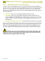
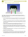
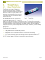
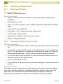
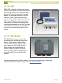
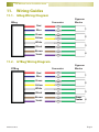
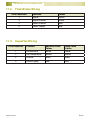
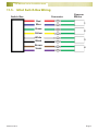
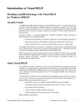
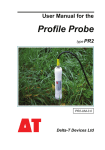
MEA
soil moisture
and
climate monitoring
with
certainty
Get a
Green
Brain
Installation Guide for
Soil
Moisture
Sensors
41 Vine Street
Magill
South Australia 5072
p
f
e
w
08 8332 9044
08 8332 9577
[email protected]
www.mea.com.au
Version 6.0
August 2012
Soil Moisture Sensor Installation Guide
Notices
Copyright
Copyright © Measurement Engineering Australia Pty. Ltd. 2012
All rights reserved. Under the copyright laws, this manual may not be copied, in whole or in part
by any means without the written consent of Measurement Engineering Australia Pty. Ltd.
Design Changes
Measurement Engineering Australia Pty. Ltd. reserves the right to change the designs and
specifications of its products at any time and without prior notice.
Contact
Measurement Engineering Australia Pty. Ltd.
41 Vine Street
MAGILL SA 5072
Telephone
08 8332 9044
Fax:
08 8332 9577
Email:
[email protected]
Web:
www.mea.com.au
Warranty
MEA offers a 12 month, return-to-factory warranty on all new logging systems and hardware.
The warranty applies to hardware, software and system defects only. The warranty does not
cover acts of misuse by the user or third parties, including misuse arising from failure to install
or operate a system or its components in accordance with relevant system documentation, or
failure to seek advice from MEA regarding correct installation or operation of a system or its
components.
Support
If you have questions or problems that cannot be resolved using the information in this manual,
contact MEA technical support using the details above. If phoning, ask for the Operations
Manager and explain the issue. The Operations Manager will assign a Technician to help resolve
the issue. Quoting your MEA Job Reference Number will enable us to quickly locate your details.
Phone support is generally available Monday to Friday between 9am and 5pm Central (ie South
Australian) Standard or Summer Time.
Site visits can be arranged but will incur charges for labour, travel time and where applicable,
accommodation and meals.
MEA technicians can only offer support for issues relating directly to the operation of Magpie
software or MEA logging systems or hardware. For general computer issues please consult a
computer technician.
www.mea.com.au
Page 2
Soil Moisture Sensor Installation Guide
Contents
1.
Introduction.............................................................................. 5
2.
General Considerations............................................................ 6
3.
4.
5.
6.
7.
2.1.
Content vs Tension........................................................................ 6
2.2.
‘Spot’ vs ‘Continuous’ Monitoring................................................. 6
2.3.
Number and Location of Monitoring Sites................................... 7
2.4.
Sensor Depths............................................................................... 7
2.5.
Make a Detailed Site Plan............................................................. 9
2.6.
Protection of Loggers and Sensor Wiring. ................................... 9
Gypsum Blocks........................................................................11
3.1.
About Gypsum Blocks. ............................................................... 11
3.2.
Which Gypsum Block?. ............................................................... 12
3.3.
Installing Gypsum Blocks............................................................ 12
ThetaProbes............................................................................ 17
4.1.
About ThetaProbes..................................................................... 17
4.2.
Installing ThetaProbes................................................................ 18
EnviroPro................................................................................ 20
5.1.
About the EnviroPro. .................................................................. 20
5.2.
Which Probe to Use. ................................................................... 20
5.3.
Installing EnviroPros................................................................... 21
5.4.
Preparation. ................................................................................ 21
5.5.
Installation. ................................................................................. 21
FullStop Wetting Front Detectors........................................... 24
6.1.
About FullStops. ......................................................................... 24
6.2.
Installing FullStops...................................................................... 25
Aquaflex Soil Moisture Sensor................................................ 28
7.1.
About Aquaflex Sensors. ............................................................ 28
www.mea.com.au
Page 3
Soil Moisture Sensor Installation Guide
7.2.
8.
9.
10.
11.
Installation of Aquaflex Sensors................................................. 29
Profile Probes......................................................................... 31
8.1.
About Profile Probes................................................................... 31
8.2.
Installing Profile Probes.............................................................. 32
W.E.T. Sensors......................................................................... 35
9.1.
About W.E.T. Sensors................................................................... 35
9.2.
Installing W.E.T. Sensors.............................................................. 35
Displays, Loggers & Software................................................. 36
10.1.
GDot............................................................................................ 36
10.2.
GDot Switch Box......................................................................... 36
10.3.
MEA Retriever. ............................................................................ 36
10.4.
GBug............................................................................................ 37
10.5.
GTBug.......................................................................................... 37
10.6.
TBug............................................................................................ 37
10.7.
ABug............................................................................................ 38
10.8.
MEA Bug Software...................................................................... 38
10.9.
HH2 Reader................................................................................. 38
10.10.
SML.............................................................................................. 39
10.11.
MEA Radio................................................................................... 39
Wiring Guides......................................................................... 40
11.1.
GBug Wiring Diagram................................................................. 40
11.2.
GTBug Wiring Diagram............................................................... 40
11.3.
ThetaProbe Wiring...................................................................... 41
11.4.
AquaFlex Wiring.......................................................................... 41
11.5.
GDot Switch Box Wiring.............................................................. 42
12.
Safety...................................................................................... 43
13.
Glossary.................................................................................. 44
www.mea.com.au
Page 4
Soil Moisture Sensor Installation Guide
1.
Introduction
Irrigation without soil moisture monitoring can be costly, wasteful guesswork.
However, poor placement or installation of soil moisture sensors will result in poor data
that does not accurately represent soil moisture conditions.
Sensors installed correctly in the right location will result in good data and can
contribute to good irrigation outcomes. The purpose of this Guide is to help you install
your soil moisture sensors in the right way, in the right place.
This Sensor Installation Guide covers the placement and installation of the following:
●● Gypsum block soil moisture tension sensors
●● ThetaProbe soil moisture content sensor
●● EnviroPro soil moisture content, salinity and temperature probes.
●● FullStop Wetting Front Detectors
●● Aquaflex soil moisture content and temperature sensors
●● Profile Probe soil moisture content sensors
●● W.E.T. soil moisture content, electrical conductivity and temperature sensors
www.mea.com.au
Page 5
Soil Moisture Sensor Installation Guide
2.
General Considerations
Before purchasing and installing soil moisture monitoring systems, a number of things
must be considered.
2.1.
Content vs Tension
The first decision to make is whether to measure soil moisture content or tension. These
two parameters are opposite sides of the same coin.
Soil Moisture Content Sensors (eg ThetaProbe, EnviroPro, Profile Probe)
Soil moisture content sensors measure how much water is contained in the pore spaces
of a given volume of soil, expressed either as a percentage (%vol) or a ratio (m3.m-3).
This is also known as volumetric soil moisture measurement. This type of measurement
can be easy to understand, as there is a direct relationship between the amount of
water applied and the amount of water contained in the soil. Volumetric sensors take
the irrigator’s point of view: “How much water do I have to apply to refill the profile?”
Soil Moisture Tension Sensors (eg Gypsum Blocks)
Soil moisture tension (also known as matric potential) sensors measure the energy
required for roots to extract moisture against the capillary forces that hold it in the soil.
The force required is measured in kiloPascals (kPa). Soil moisture tension sensors take
the plant’s point of view: “How hard is the plant having to work to extract moisture
from the soil?”
2.2.
‘Spot’ vs ‘Continuous’ Monitoring
‘Spot’ Monitoring Systems
In ‘spot’ monitoring, soil moisture readings are taken one at a time with a hand-held
Reader. In some instances the Reader is able to store the readings in memory for later
retrieval. In order to obtain detailed data the user must perform many measurements
as the only moisture value available is the one present at the time the sensor is
read. The relatively low costs of ‘spot’ monitoring will allow for a greater number of
monitoring sites, but monitoring resolution and the ability to analyse trends in water
use will be limited by the time available to perform measurements.
‘Continuous’ Monitoring Systems
In ‘continuous’ monitoring systems, a data recorder reads a sensor or number of sensors
at set intervals and stores the values in memory for later retrieval. Sensors are read
frequently and automatically, and some cases the ‘read interval’ is programmable. Data
can be retrieved with a ‘shuttle’ storage device such as an MEA Retriever, by connecting
a PC to the Logger with a cable, or transferred to the Internet. Retrieved data is
downloaded to a computer and can be viewed as tables or graphs, allowing analysis of
www.mea.com.au
Page 6
Soil Moisture Sensor Installation Guide
water use and soil moisture trends over time. Changes in soil moisture and other values
such as rainfall can be easily and accurately monitored, and the grower’s time is freed
to perform other tasks.
2.3.
Number and Location of Monitoring Sites
Some ‘rules of thumb’ can be applied when considering the number and location of
sites:
●● One site per irrigation shift, OR
●● One site per plant variety, OR
●● One site per soil type
●● Find an ‘average’ plant away from the edges of the crop
●● Ensure that the dripper or sprinkler works and the flow-rate is correct
●● Check that there is no surface runoff due to slopes, mounding or terracing, and
that water does not pool at the intended installation site
●● Place sensors in the wetted pattern after first irrigating on dry soil to show where
the water goes
Start with the minimum number of sites required to provide the information needed to
manage the property. Observations made over time will allow you to determine if more
or fewer monitoring sites are required.
2.4.
Sensor Depths
Enough sensors should be installed to give a representative picture of what is
happening through the root zone and to match the soil profile. If there are discrete
soil layers in the profile, each should be monitored. In most cases monitoring at 3 or 4
depths is adequate. If there is a hard pan or impervious layer, a sensor should be placed
just above it, to detect the presence of a perched water table. If gypsum blocks are
used, use GBLites for sand or loam layers, and GBHeavies for clay-heavy soils (a mix of
sensors with the one logger is OK)
In vines and citrus, 3 sensors are usually placed in the root zone, with an extra sensor
just below the root zone to detect drainage.
In annual and shallow rooted crops, 1 or 2 sensors in the root zone and another for
drainage is sufficient.
www.mea.com.au
Page 7
Soil Moisture Sensor Installation Guide
Many sources cite typical root zone depths for annual and permanent crops, for
example 1 m for vines. The plant root zone can differ from this considerably (and vary
between sites as well). A layer of clay, rock or sodic soils can limit the root zone to much
less than this; in a friable or gravely soil, the roots can penetrate much deeper. The only
way to know for certain is to excavate a soil pit or take core samples.
Once rainfall has been depleted in the soil profile, the only active roots feeding the
plant are within the wetted zone of the irrigation dripper or sprinkler. Sensors must be
placed in this zone, where they will measure the ‘water of last resort’.
Typical % Water
Typical % Root Zone
Top sensor detects rainfall and shallow irrigations
40%
30%
20%
10%
Transpiration
Fig. 1.
www.mea.com.au
25%
Active root-zone sensor. Most useful
for irrigation decisions
Sensor
Drainage
sensor
25%
25%
25%
Drainage
The relationship between root depth and water use. The plants will draw
water firstly from the upper levels, with deeper water being sought out once
the upper levels dry out.
Page 8
Soil Moisture Sensor Installation Guide
2.5.
Make a Detailed Site Plan
Sensor installation will be easier if a detailed site plan is prepared prior to installation.
Include the name of each measurement site (eg. Shiraz, Merlot etc.), the depths or
positions at which the sensors are to be installed (eg. 20cm, 50cm etc.), the type
of Logger if a mix of types is used, and the type of sensor (eg. GBLite, GBHeavy,
temperature, Aquaflex) installed at each location.
2.6.
Protection of Loggers and Sensor Wiring
Protect loggers and any exposed sensor wiring
from damage by animals or machinery. This is best
implemented at the time of installation.
Sensor wiring can be protected by enclosing it
in electrical conduit or polypipe, or by burying it.
Sensor cables can be extended in order to obtain
more distance between the sensors and logger so
that the logger can be placed in a secure location.
Loggers can be mounted to a convenient strainer
post or to a hardwood stake, or installed inside
galvanised channel as per the photograph at right:
●● The height of the post should be set to match
the type of machinery or plant being used at
the site
●● If installing in vineyards, set the top of the
post below the height of the fish plates on the
harvester
●● If installing in crops irrigated using a centre
pivot or lateral move system, ensure that
the top of the post is lower than the irrigator
boom
Fig. 2.
An MEA GBug installed
inside ‘C-channel’
for protection from
machinery. Sensor
wiring is enclosed in
32mm conduit.
●● In tall crops, a bicycle flag can be fitted to the top of the stake to help locate the
site, or a mark made on an end-post to alert machinery operators to the presence
of the logger
www.mea.com.au
Page 9
Soil Moisture Sensor Installation Guide
Protection is also about finding the right location for the equipment. In vineyards for
example, loggers or radios should be installed ‘inside’ the vine row where they will be
out of the way of machinery or workers (the sensors themselves should be located as
per the advice given later in this publication). Ensure that the logger enclosure is not
being sprayed directly by sprinkler systems.
Fig. 3.
www.mea.com.au
A GBug soil moisture logger installed ‘out of the way’ in a vine row.
Page 10
Soil Moisture Sensor Installation Guide
3.
Gypsum Blocks
Fig. 4.
3.1.
GBHeavy and GBLite
About Gypsum Blocks
Gypsum blocks are a type of soil moisture tension sensor, and use the same readout
units as the industry standard tensiometer - kilo pascals (kPa). Gypsum blocks are
one of the lowest cost soil moisture monitoring products available. A block of porous
gypsum placed in the soil will wet up and dry out in a similar manner to the soil itself.
A gypsum block in wet soil conducts electricity easily, and poorly in a dry soil. A pair of
electrodes within the block measure this change and a standard calibration equates
the resistance of the block to soil moisture tension.
Gypsum blocks can be used with:
●● MEA’s GBug or GTBug loggers in conjunction with an MEA Retriever and MEA Bug
software for continuous soil moisture monitoring
●● MEA’s GBReader or GDot (with optional GB Terminal) for ‘spot’ monitoring
●● MEA Radio systems for continuous monitoring over a wide area
See “10. Displays, Loggers & Software” on page 36 for more information.
www.mea.com.au
Page 11
Soil Moisture Sensor Installation Guide
3.2.
Which Gypsum Block?
MEA’s GBHeavy (MEA2176) is best suited to a tension range of 50 to 500 kPa (the range
found in heavy soils having a high clay content). The GBLite (MEA2195) is calibrated
over a tension range of 10 to 200 kPa (sand to sandy clay loam).
The choice of which type of block to use is simple: if moisture levels are to be kept in
the range where it is readily available to the plants, use the GBLite regardless of soil
type. Where the crop is going to be pushed into deficit, (e.g. with Partial Root Zone
Drying and Regulated Deficit Irrigation), use the GBHeavy in soils with a substantial clay
content and the GBLite in sandy soils. The GBHeavy sensor also makes a cost efficient
drainage detection sensor when used below a set of GBLites.
3.3.
Installing Gypsum Blocks
3.3.1.
What You Will Need
●● 25mm Auger (MEA2193)
●● Masking tape or electrical tape
●● 13mm (½”) PVC pressure pipe, 1.2m in length
●● Trowel
●● Bucket & water
●● Active Gel Bentonite (MEA2197, 2kg pack will cover 15 - 20 sensors)
●● Dry builder’s sand
●● 12mm dowel, 1.2m length
●● Tape measure, notebook, tags & permanent marker
●● GBReader or Bug and Retriever to test blocks
www.mea.com.au
Page 12
Soil Moisture Sensor Installation Guide
3.3.2.
Where to Place the Blocks
Drip Irrigation
Install the sensors at four
different depths, equally spaced
on the circumference of a 10
~15 cm radius centred directly
under the dripper. Mark the
locations to make it easier to
auger the holes. Install each
sensor in its own hole - stacking
the blocks vertically can lead
to leakage down the hole, and
makes it difficult to replace
individual sensors if later
required.
Pre-marked
installation
site for each
block.
Circle of 10 ~ 15 cm
radius centred under
dripper.
Fig. 5.
Holes marked under a dripper
prior to augering.
Sprinklers
Install the sensors in a straight line 10cm apart, in a location where the sprinklers are
delivering their rated output.
3.3.3.
Getting the Blocks in the Ground
●● Mark the Auger with tape at the
installation depths, and auger holes for
the sensors one at a time
●● Keep the soil removed, you will need it to
help correctly seal the sensors
●● Pour half a cup of water down the holes
to ensure correct seating of the sensors
●● Unwrap the foil from the GBHeavy blocks
or unpack the GBLites from their plastic
bags. Do not touch the sensors as the oils
in your skin can block the surface pores of
the blocks
●● Soak the sensors in a bucket of clean
water for around 15 minutes
●● While the sensors are soaking, mark up
the 1/2-inch PVC pressure pipe with the
installation depths (don’t forget to allow
for half the sensor length)
www.mea.com.au
Fig. 6.
Augering holes with an
Auger pre-marked with the
installation depths.
Page 13
Soil Moisture Sensor Installation Guide
●● Push the cable from the sensor up through the pipe
●● Hold the cable taut and use the pipe to gently push the sensor into the hole
●● Use the marks on the pipe to ensure the
sensor is at the intended depth
●● Withdraw the pipe
●● Pour a handful of earth down the hole
and gently compact with the dowel
●● Mix 1 part Active Gel Bentonite with 4
parts fine dry sand and backfill the hole to
around 25 mm from the top
●● Use more earth to complete filling the
hole. Do not overfill as this will form a
surface cap which will shed water away
from the sensor
●● Use the permanent marker to label the
sensor wire with the depth, installation
date and sensor number (a cattle tag is
useful for this)
Fig. 7.
Using PVC pipe to insert the
sensors.
●● Connect the sensor to the Bug or GB Terminal using the supplied wiring diagram
and low voltage irrigation connectors - see “3.3.5. Using Low Voltage Irrigation
Connectors” on page 16
●● Once all sensors are connected, confirm the connections are good by taking
a reading - it should show ‘wet’ since the sensor was saturated just prior to
installation
Installing GBLites in Shallow Root Zones
In many vegetable crops, the root zone can be very shallow – under 20 cm. The active
feeder roots of citrus, particularly when grown in sandy soils can also be quite shallow.
The GBLite sensors can be installed at shallow depths by simply laying the sensor
horizontally in the soil in a hole opened up with a spade or trowel (in place of the
gypsum block auger). Install using Silica Flour (see “3.3.4. Improving the Sensor-to-Soil
Contact” on page 15). In very sandy soils, this technique can also improve water flow into
and out of the sensor.
GTBug Temperature Sensor
The temperature sensor should be installed between 100 mm and 150 mm where daily
fluctuations in surface temperature are minimised. This sensor can simply be placed in
a hole of the correct depth and backfilled, gently compacting the soil as you go.
www.mea.com.au
Page 14
Soil Moisture Sensor Installation Guide
3.3.4.
Improving the Sensor-to-Soil Contact
In reactive clay soils and in light sands, the installation procedure can be modified to
improve soil to sensor contact. This avoids problems with clay soils shrinking away from
the sensors or with sandy soils drying down faster than the sensor can respond. The
change involves bedding the sensors in a slurry of intermediate material. Three types of
slurry may be used:
●● Clay loam: mix a slurry using clay loam found elsewhere on site
●● Silica flour: make a slurry using 300 or 400 grade silica flour (MEA2198, 1 kg
pack). Feedback from MEA field agents indicates that in sandy soils, sensor to soil
contact for GBLites can be improved by simply dipping the saturated sensor into
dry Silica flour
●● Silica flour and diatomaceous earth: make a 50/50 slurry of these two materials
Fill a jar to 90% capacity with the chosen material; top up with water, put on the lid and
shake until mixed. A small quantity of the slurry can be poured into each hole or else
the sensor can be dipped into a jar of the slurry to coat it prior to installation - only a
thin coat is required. The GTBug temperature sensor does not require this treatment.
Silica flour can cause serious lung disease and irritation to the eyes and
respiratory system. Please comply with the precautions advised in the Material
Safety Data Sheet supplied with the Silica flour
www.mea.com.au
Page 15
Soil Moisture Sensor Installation Guide
3.3.5.
Using Low Voltage Irrigation Connectors
Wire from Bug
Wire from sensor
Low voltage irrigation connectors are supplied for connecting gypsum blocks to
GBugs, GTBugs or GBSwitches. If you have not used these connectors previously, the
following notes will be of use:
●● Use one connector per join (two per gypsum block). The connectors have three
holes - use one for a sensor wire, and one for a Bug wire - leave the third hole
unused
●● Don’t strip the insulation from the wires to be joined. The metal plates inside the
connectors work by displacing the insulation, and stripping it back can result in a
poor connection.
●● GBLite sensor wires are sometimes terminated with a small ring connector - this
will have to be cut off before insertion into the irrigation connector
●● Push one wire from the gypsum block and the relevant coloured wire from the
Bug into the connector as far as they will go. The connectors are translucent on
the opposite side of the black button so you will be able to see when the wires are
all the way in
●● Holding the wires in place, use pliers or multi-grips to push the black button on
the connector all the way down
●● Repeat for all remaining connections
●● After all the blocks are connected, ensure that the end of the Bug cable is off the
ground and pointing downward so that water is not able to collect in the cable.
For added protection you can wrap the end of the cable in waterproof tape
www.mea.com.au
Page 16
Soil Moisture Sensor Installation Guide
4.
ThetaProbes
4.1.
About ThetaProbes
ThetaProbes are a type of volumetric
soil moisture content sensor. The probe
consists of a waterproof housing containing
electronics with an array of stainless steel
electrodes at one end (for direct insertion
into undisturbed soil) and a power/signal
cable at the other.
Fig. 8. ThetaProbe
The ThetaProbe measures soil moisture
content with an accuracy of ± 1% over the
range of 0 to 60% of volumetric soil moisture content. This level of accuracy makes
the probe suitable for use where soil moisture levels are to be tightly controlled, and
in critical applications such as hydrology, soil stability studies, soil water profiling,
pollution monitoring, water leakage detection from pipes and dams, ground-truthing
and forestry.
ThetaProbes can be used with:
●● TBug, MEA Retriever and MEA Bug software
●● MEA Radio system to provide continuous soil moisture monitoring
●● HH2 Reader to provide ‘spot’ measurements that can be downloaded to a PC
See “10. Displays, Loggers & Software” on page 36 for more information.
www.mea.com.au
Page 17
Soil Moisture Sensor Installation Guide
4.2.
Installing ThetaProbes
4.2.1.
What You Will Need
Surface Installation
●● Reader or TBug and Retriever
Buried Installation
●● Spade or trowel for shallow installation, 40mm Auger (MEA2192) for deeper
installation
●● Masking tape or similar
●● 32mm (1¼”) pressure pipe or similar, 300mm longer than the deepest installation
depth
●● Active Gel Bentonite (MEA2197)
●● Dry builder’s sand - 4 times the quantity of bentonite
●● 12 mm dowel, length as above
●● Tape measure, notebook, tags & permanent marker
●● Reader or TBug and Retriever
4.2.2.
Getting the Probes in the Ground
Surface Installation
●● For surface installation the stainless steel rods can just be pushed into undisturbed
soil
●● If the probe is going to be left in place, it is a good idea to insert it at a slight angle
(eg 10°~20°) so that water running down the outside of the probe is less likely to
pool around the electrodes - make sure the electrodes are completely covered
●● Try to ensure there are no air pockets or stones around the electrodes as this will
reduce the quality of the measurements
●● Take care not to bend the rods
●● Use your Reader or TBug-and-Retriever to take a reading to verify operation of the
probe(s)
Buried Installation
The need to monitor a particular part of the root zone can require a buried installation.
Even with a shallow installation, it might be preferable to bury the probe to provide
protection for it. ThetaProbes can be installed either horizontally or vertically
depending on the depth of installation and installation equipment available.
www.mea.com.au
Page 18
Soil Moisture Sensor Installation Guide
Installing a ThetaProbe Horizontally
The probes may be installed horizontally in shallow sites. The sensor should be inserted
into undisturbed soil on the face of the trench:
●● At the monitoring site, excavate a trench down to 10 cm below the sensor depth.
Clean off the face of the hole at the required depth
●● Push the rods into the side of the hole until the soil comes in contact with the
probe body
●● Route the sensor cable out of the hole to the surface (it can be sheathed in
conduit to protect it against damage)
●● Carefully backfill under and around the sensor
Installing a ThetaProbe Vertically
●● Use the masking tape to mark the Auger with the installation depth(s)
●● Auger the hole. As with surface installation, it is a good idea to auger the hole on
a slight angle (eg 10°~20°) to prevent water collecting at the rods
●● Thread the probe cable and connector (if fitted) through the pressure pipe and
use this to push the sensor down the hole, pushing the rods into the undisturbed
earth at the bottom of the hole. Take care not to bend the rods
●● Withdraw the pipe
●● Pour a handful of earth down the hole and gently compact with the dowel
●● Mix 1 part Active Gel Bentonite with 4 parts fine dry sand and backfill the hole to
around 25 mm from the top; use the dowel to gently compact as you go
●● Use more earth to complete filling the hole. Do not overfill as this will form a
surface cap which will shed water away from the sensor
●● Connect the probe to the TBug or other Reader and take a reading
www.mea.com.au
Page 19
Soil Moisture Sensor Installation Guide
5.
EnviroPro
5.1.
About the EnviroPro
EnviroPro probes provide reliable soil moisture,
salinity and temperature measurement in all soil
types. Multiple sensor clusters per probe at 100 mm
spacings allow the monitoring of moisture, salinity
and temperature at each sensor depth. Soil moisture
readings are temperature-compensated and can be
salinity-compensated.
The internal electronics are fully protected, making the
probes reliable, consistent and very stable.
Each probe is supplied with 5 m of cable. Designed to
be completely buried, the EnviroPro is ‘out of the way’
when slashing, spraying and harvesting.
Moisture profiling at 100mm intervals allow you
Fig. 9. EPSM4.
to track the movement of water through the root
zone and optimise irrigation events. Following the
movement of nutrients through the root zone by tracking changes in salinity allows
you to optimise fertiliser applications and only apply leaching irrigations when needed.
EnviroPros can be used with:
●● MEA SML
●● MEA Radio
See “10. Displays, Loggers & Software” on page 36 for more information.
5.2.
Which Probe to Use
The choice of probe to use will be determined by the size of the root zone or profile
height to be monitored. The EPSM4 has 4 sensor clusters and is 500 mm long. The
EPSM8 has 8 sensor clusters and is 900 mm long. The EPSM12 is 1300 mm long. The
EPSM16 is 1700 mm long.
www.mea.com.au
Page 20
Soil Moisture Sensor Installation Guide
5.3.
Installing EnviroPros
5.4.
Preparation
The EnviroPro should be installed using a fine sand and bentonite slurry to ensure there
are no air gaps between the probe and the surrounding soil.
The quantities and method described below will make a sufficient quantity of slurry for
the installation of 2 EP100C-08 or EP100CL-08 probes, which are 80cm long.
5.4.1.
Materials and Equipment Required
●● 1kg of fine sand (eg unimin AFS85 grade).
●● 100gm Bentonite (civil grade eg Unimin Active Gel 150).
●● 1L clean water.
●● Small bucket with lid.
●● Funnel.
●● 2L plastic bottle with lid.
5.4.2.
Method
1. Mix the dry bentonite and sand together in a bucket.
2. Pour the dry mix through the funnel into the 2L plastic bottle.
3. Pour the water into the bottle, put the lid on and shake until thoroughly mixed.
The slurry is ready for use after 15 minutes.
4. Always shake the mixture before application (the sand might settle in storage).
5.5.
Installation
5.5.1.
Tools Required
●● 36 - 38mm Auger.
●● Tape measure and adhesive tape.Where to Place an EnviroPro
Drip Irrigation
Similarly to Gypsum blocks, an EnviroPro should be placed somewhere within a 10 to
15 cm radius of the dripper, but not directly beneath the dripper.
Sprinkler Irrigation
Place an EnviroPro where the sprinkler is delivering its rated output. In tree crops and /
or where overhead sprinklers are used, locate the EnviroPro at the drip-line of the tree.
www.mea.com.au
Page 21
Soil Moisture Sensor Installation Guide
5.5.2.
Getting the Probe in the Ground
●● Use the tape measure and the adhesive tape to mark the auger 10 cm longer than
the probe to be installed.
●● Auger a hole 10 cm deeper than the probe to be installed. Use the tape measure
to check the depth after the auger is extracted to ensure that part of the hole wall
has not collapsed or that other material has not fallen into the hole.
●● Pour slurry into the hole until it is 50% full.
●● Push the probe into the hole until the top is 25 mm below the soil surface. Apply
a maximum of 15 kg of force to the probe. Avoid causing sharp bends in the cable
where it enters the probe.
●● The slurry should ooze up around the instrument and slightly overflow the hole.
If you do not see any slurry, carefully extract the instrument, mix up some more
slurry and add to the hole
●● Backfill to cover the probe
●● Trench the cable in to a depth of 100 mm or deeper to protect it.
Fig. 10. Mark the Auger at the required
installation depth.
www.mea.com.au
Fig. 11. Dig the hole using a 36mm Auger.
Page 22
Soil Moisture Sensor Installation Guide
Fig. 12. Add the slurry to the hole.
Fig. 13. Push the probe into the hole.
The slurry should ooze up as the
instrument is inserted.
●● Connect the EnviroPro to your reader or logger and wait for a reading to ensure
the probe is operational. Readings should be at least slightly wet until the water
content in the slurry and surrounding soil have equalised.
www.mea.com.au
Page 23
Soil Moisture Sensor Installation Guide
6.
FullStop Wetting Front Detectors
6.1.
About FullStops
The FullStop provides a cost effective method of
assessing whether too much or too little irrigation
is being applied, to detect water logging and to
monitor nutrient and salt levels in the soil.
The heart of the FullStop is a funnel shaped collector
which is buried in the soil. As moisture moves
through the soil profile (a wetting front), it converges
in the funnel and collects in a reservoir in the base of
the unit.
An indicator flag is fitted to an extension tube which
protrudes above ground. When water collects in the
base of the funnel, floats within the extension tube
cause the indicator flag to pop up to show that the
wetting front has arrived. The indicator flag is held
Fig. 14. A FullStop Wetting
up with a magnetic latch and must be pushed down
Front Detector
to reset it. If the soil is still very wet, the flag will pop
up again. An outlet tube at the base of the FullStop
allows water collected in the funnel to be extracted using a syringe, and tested for EC
and nitrate levels.
Unlike the other sensors in this guide, the FullStop requires no power source, Readers,
Loggers or software.
www.mea.com.au
Page 24
Soil Moisture Sensor Installation Guide
6.2.
Installing FullStops
6.2.1.
What You Will Need
●● 20 cm and 5 - 10 cm Augers (or shovel and trowel if you don’t have access to the
Augers)
●● Tape measure
●● Portable EC Meter (MEA2272) for monitoring salinity levels
●● Nitrate and nitrite test strips (MEA2273 and MEA2274) for monitoring nutrient
levels
6.2.2.
Where to Place the FullStops
FullStops are sold and generally used in pairs, with one unit at one third of the root
depth, and the second at two thirds of the root depth.
Drip Irrigation
●● The detector must always be placed directly
under a dripper. Suggested depth for the shallow
detector is 30 cm and for the deep detector is
60 cm
●● Deeper placement is required for widely spaced
drippers or long irrigation intervals. Shallower
placement suits closely spaced drippers, frequent
irrigation or shallow rooted crops
●● It is common for detectors to respond quickly
under drip because all the water is being
concentrated around the dripper, with dry soil
between drippers. In such cases less water should
be applied more often
www.mea.com.au
Page 25
Soil Moisture Sensor Installation Guide
Sprinkler or Microjet Irrigation
●● Wetting patterns tend to be shallower under
sprinkler irrigation than drip or furrow irrigation
●● Suggested depth for the shallow detector is
20 cm and for the deep detector is 40 cm. Note
that it usually takes 20 mm or more of irrigation
to activate a detector at 20 cm (depending on soil
type and on how dry the soil is before irrigation)
●● For sprinkler systems that apply small amounts
of water each day or second day (e.g. microjets
or centre pivot), depths of 15 cm and 30 cm are
more suitable (5 cm and 20 cm to the rim of the
funnel). Detectors will usually not be activated by
applications under 15 mm, unless the soil is quite
wet before irrigation
Furrow Irrigation
●● Detectors should be positioned half under the
furrow and half under the bed with the extension
tube rising through the shoulder of the bed
●● Suggested depth for the shallow detector is 20
~ 30 cm and for the deep detector is 40 ~ 60 cm
(from the base of the furrow). Deep rooted crops
with less frequent irrigation would require deeper
placement
www.mea.com.au
Page 26
Soil Moisture Sensor Installation Guide
6.2.3.
Getting the FullStops in the Ground
Following are instructions for installing the FullStops using Augers. A shovel can be
used in place of the large Auger, and a trowel can be used in place of the small Auger.
●● Assemble and test the FullStops according to the instructions that came with
them. Check for leaks, and make sure the float indicator can move freely through
the extension tube(s). Attach as many extension tubes as required for the
installation depth
●● Make a hole with the large Auger. This will accommodate the wide part of the
funnel
●● When the hole is deep enough, use the small Auger to make a hole for the
bottom of the FullStop
●● If the soil texture changes with depth, keep the different soil layers separate
●● Add the filter sand (supplied with the FullStops) to the detector until it covers the
locking ring by at least 1 cm
●● Place the detector in the hole and measure the distance to the rim of the funnel
to check that it reaches the required depth
●● Make sure the extension tubes are vertical
●● Fill the funnel with soil from the same layer, and lightly firm it down
●● Break up the sides of the hole before returning more soil, as smooth sides can
restrict the growth of roots and the movement of water
●● Pack soil around the sides and under the funnel to keep it firmly in place (hold the
outlet tube out of the way) - the deeper narrow hole does not need to be packed
with soil
●● Return the rest of the soil to the hole in the layer order in which it was extracted
●● Soil should be firmed down by hand, but not compacted
●● Use the trowel to break up the top edge of the hole
●● All the soil should be returned to the soil, leaving a slight ‘hump’ which should
settle after rain or irrigation. After settling, check that the soil is level so that water
does not run away from or toward the detector
●● Push the tubing stake (supplied with the FullStop) into the end of the outlet tube
(this will prevent insects and soil from entering and blocking the tube) and use it
to position the tube away from the detector
For more information please visit www.fullstop.com.au
www.mea.com.au
Page 27
Soil Moisture Sensor Installation Guide
7.
Aquaflex Soil Moisture Sensor
Fig. 15. An Aquaflex Soil Moisture Sensor (Model SI.99) - with
the 3m sensor tape rolled up.
7.1.
About Aquaflex Sensors
The Aquaflex is a type of soil moisture content sensor. The sensor consists of a yellow
waterproof housing containing electronics, and a 3 m ribbon cable (the sensor) which is
installed on its edge. The Aquaflex averages soil moisture over its sensor length which
results in a sampling volume of 6 litres of soil. It measures soil moisture content over
the range of 0 to 60% with an accuracy of ±2%, and soil temperature over the range
of -10° to 50°C. The Aquaflex is suitable for use in hydrology, soil stability studies, soil
water profiling, pollution monitoring, water leakage detection from pipes and dams,
ground-truthing and forestry. The major use of the Aquaflex sensor is to manage
irrigation practices in shallow-rooted crops such as turf, sports grounds, parklands, golf
courses, pasture applications and in horticulture - especially vegetable crops
The Aquaflex is capable of 2 different types of output:
●● Frequency (for connection to pulse inputs devices such as flow meters). This
output delivers soil moisture only
●● 4 to 20 mA current loop. Two separate outputs for soil moisture and temperature
The Aquaflex can be used with:
●● ABug, MEA Retriever and MEA Bug software for continuous soil moisture and
temperature monitoring
See “10. Displays, Loggers & Software” on page 36 for more information.
www.mea.com.au
Page 28
Soil Moisture Sensor Installation Guide
7.2.
Installation of Aquaflex Sensors
7.2.1.
What You Will Need
●● String line to mark position of slit or trench
●● Turf cutter or spade for shallow installation, shovel for trenching for deeper
installations
●● Water to ‘bed-in’ the sensor after backfilling
●● ABug and Retriever or Handheld Reader
7.2.2.
Where to Place the Aquaflex
Shallow-roooted Crops (eg Turf or Pasture Grasses)
●● Install the sensor sloping downward through the profile from around 50 mm
below the surface to around 400 mm
●● A second Aquaflex can be installed at around 500 mm as a ‘check’ sensor to help
identify over-watering
Fig. 16. An Aquaflex installation under pasture
www.mea.com.au
Page 29
Soil Moisture Sensor Installation Guide
7.2.3.
Getting the Aquaflex in the Ground
Shallow Installations (eg Turf)
●● Select and mark the position of the
sensor with a string line. Position the
sensor where it can be easily located
in future – e.g. on a marker line on a
sports field
●● With a turf cutter or sharp, flat blade,
carefully cut a slit in the turf
●● Carefully insert the sensor into the
slit to the desired depth
Fig. 17. Installing an Aquaflex in turf.
●● For the electronics block at the end
of the sensor, carefully peel back
sufficient turf to create a slightly larger and deeper cavity in which to bury the
block - ‘wedge’ side up, and fold the turf back into position
●● Gently push from behind each side of the sensor slit to close it. Pack from the
sides to recreate original density and remove air pockets
●● Repair and smooth as necessary
●● Apply a liberal amount of irrigation/water to allow the sensor to bed in and
remove air pockets
●● Run the data cable in a slit or trench to the desired location
●● Take a reading with the Handheld reader or ABug and Retriever
Hint: It is essential that the sensor cable be installed on its edge to prevent water
pooling on the cable, which will give false moisture readings. Ensure the sensor is
installed deep enough to avoid damage during site maintenance. After installation,
allow time for the disturbed soil to settle before using the data from your Aquaflex
Sensors. This can take some time depending on the soil conditions. The settling process
can be accelerated by applying several heavy irrigations, ideally taking the soil to
saturation each time.
www.mea.com.au
Page 30
Soil Moisture Sensor Installation Guide
8.
Profile Probes
8.1.
About Profile Probes
A Profile Probe is a type of soil moisture content sensor, configured
to measure moisture content at a number of different levels,
providing a Soil Moisture Profile. Users can choose between:
●●
the PR2/4, measuring at 4 depths: 10, 20, 30 & 40 cm, or
●● the PR2/6 measuring at 6 depths: 10, 20, 30, 40, 60 & 100 cm.
The probes have low sensitivity to salinity and temperature.
Connectors are sealed to IP68 (submersible). Extension cables are
available.
A Profile probe can be used with:
●● HH2 Reader for ‘spot’ measurements
●● a Data Logger for continuous soil moisture monitoring
See “10. Displays, Loggers & Software” on page 36 for more information.
Fig. 18. PR2/6
Profile
Probe
www.mea.com.au
Page 31
Soil Moisture Sensor Installation Guide
8.2.
Installing Profile Probes
8.2.1.
What You Will Need
Profile Probes are installed using closed-bottom access tubes of a length suitable to the
type of probe in use. In short, a 27 mm hole is augered, the tube is driven into the hole,
and the PR2 probe is inserted into the access tube to take readings. Optimal contact
between the soil and the access tube is essential, and the use of a purpose-designed
Augering Kit is recommended. An augering kit may be available for loan or purchase from
MEA.
The most comprehensive augering kit, PR-ACK1, consists of:
●● A Stabilisation Plate (to keep the augered hole vertical, and to help prevent
‘funnelling’ of the hole while it is being augered) and centring bushes
●● Pilot and Finishing Augers for ‘standard’ installation
●● An Insertion Rod for driving the access tube into the augered hole
●● Dead-blow mallet to use with the Insertion Rod
●● Access tube(s)
●● A cleaning rod for cleaning the inside of the Access Tubes
●● A set of ‘flexicanes’ for marking the location of Access Tubes
●● A carry bag for all of the above
In addition to the equipment contained in the Augering Kit, the following items are
useful:
●● Mist sprayer to help lubricate Augers
●● Stiff brush and cleaning cloths to help clean Augers
●● Bucket
●● Access Tube caps or bungs (where the Access Tube will be left on site)
www.mea.com.au
Page 32
Soil Moisture Sensor Installation Guide
8.2.2.
Getting a Profile Probe in the Ground
A 25-page Profile Probe Augering Manual is available which covers installation in
various soil types in detail, and users of Profile Probes are encouraged to refer to it. The
following procedure covers a ‘standard’ installation in ‘normal’ soil:
Pilot Auger
●● Choose a patch of ground that is as
level and free of stones as possible
●● Assemble and secure the
Stabilisation Plate and fit the white
centring bush
●● Push the Pilot Auger through the
centring bush by approx. 100 mm
●● Ensure the top of the Auger does
not wobble
Fig. 19. Stabilisation Plate with white
centring bush fitted
●● Use a mist-sprayer or similar to
lubricate the outside of the auger
with water during augering. Rotate the Auger as you withdraw it. It also helps
to rotate the Auger every few centimetres during insertion, to help keep it on a
straight path
●● Clean the extracted soil from the Auger
●● Repeat the process until the hole is deep enough
Finishing Auger
●● Fit the blue centring bush to the Stabilisation
Plate
●● Insert the Finishing Auger through the
centring bush and rotate clockwise, applying
a lubricating mist of water all the time
●● Aim to auger 100 ~ 200 mm at a time
●● Retract the Auger while rotating it anticlockwise
●● Clean the extracted soil from the auger
●● Repeat the process until the hole is deep
enough
www.mea.com.au
Fig. 20. Finishing Auger inserted
through the blue
centring bush
Page 33
Soil Moisture Sensor Installation Guide
Inserting the Access Tube
●● Check that the augered hole is deep enough
●● Fit the yellow centring bush to the Stabilisation
Plate
●● Start pushing the Access Tube into the hole
using the Insertion Rod
●● If you meet sufficient resistance, you will need
to use the mallet. Hold the Access Tube steady
to prevent wobbling
●● Continue until the top of the Access Tube is
level with the top of the centring bush
●● Leave the Insertion Rod in place to prevent
material falling down the Access Tube, and
remove the Stabilisation Plate
●● Remove the Insertion Rod
Completing the Installation
●● If necessary, clean the inside of the Access Tube
before inserting the Profile Probe
Fig. 21. Inserting the Access
Tube
●● Insert the Probe and take 3 readings, rotating the Probe through 120° increments.
Unexpectedly low readings could indicate the presence of air gaps or stones, and
the user will need to consider re-installation
●● If the Access Tube is to be left in position, fit a Black cap (where the top of the
Tube is above ground level), or a Red bung (if the top of the Tube is at ground
level)
www.mea.com.au
Page 34
Soil Moisture Sensor Installation Guide
9.
W.E.T. Sensors
9.1.
About W.E.T. Sensors
The WET Sensor is a multi-parameter sensor
for use in soils, composts and other artificial
growing media. It measures Water content,
Electrical conductivity, and Temperature.
In five seconds the probe can provide a measure
of water content over the range of 0 to 80%,
pore-water conductivity from 0 to 600 mS.m-1,
and temperature over the range of 0 to 40°C.
The W.E.T. sensor is used with:
●● HH2 Reader, which needs to be loaded with
the sensor’s unique calibration.
Fig. 22. W.E.T Sensor
See “10. Displays, Loggers & Software” on page 36 for more information.
9.2.
Installing W.E.T. Sensors
If the W.E.T. sensor is to be installed in a fixed location, remember that although
the sensor housing is waterproof, the connector used to attach it to a HH2 Reader is
not. You will have to find some means of ensuring that water does not enter the
connector.
Installation equipment, procedures and considerations are the same as for
ThetaProbes. Please see “4. ThetaProbes” on page 17, or refer to the W.E.T. User Manual
www.mea.com.au
Page 35
Soil Moisture Sensor Installation Guide
10. Displays, Loggers & Software
10.1. GDot
The GDot is used with a single GBLite for displaying soil
moisture tension measurements. The GDot will run for
several years on a pair of alkaline AA batteries. It never
needs adjustment or calibration and can be installed in
minutes with the most unsophisticated equipment. For
more information, please go to www.gdot.com.au
10.2. GDot Switch Box
The GDot Switch Box is a switching device which allows
users to read up to 4 gypsum blocks using 1 GDot. Blocks
are selected using a simple rotary switch.
10.3. MEA Retriever
The MEA Retriever is used to store
data from our Bug range of loggers. It
can accept data from Bugs connected
to gypsum blocks, temperature
sensors, ThetaProbes, and Aquaflex
sensors. Data is downloaded to
MEA Bug software for analysis. The
Retriever can store data from up to
100 sites for up to 20 days each.
www.mea.com.au
Page 36
Soil Moisture Sensor Installation Guide
10.4. GBug
The GBug can be connected to up to 4 gypsum blocks
(GBHeavies and / or GBLites) for continuous soil moisture
monitoring. It can store 20 days of readings Stored data is
transferred to an MEA Retriever for download to MEA Bug
software for analysis.
10.5. GTBug
The GTBug can be connected to up to 3 gypsum blocks. A
soil temperature sensor is factory fitted. The GTBug can store
20 days of readings. Stored data is transferred to an MEA
Retriever for download to MEA Bug software for analysis.
10.6. TBug
The TBug is used with ThetaProbe soil moisture
content sensors. It can accept up to 4 sensors. It can
store 8 days of data at 15-minute increments and a
further 20 days of data at 2-hour increments. Stored
data is transferred to an MEA Retriever for download
to MEA Bug software for analysis.
www.mea.com.au
Page 37
Soil Moisture Sensor Installation Guide
10.7. ABug
The ABug is used with Aquaflex soil moisture
content sensors. It can accept 2 sensors. It can
store 8 days of data at 15-minute increments
and a further 20 days of data at 2-hour
increments, and log both moisture content and
soil temperature from each one. Stored data is
transferred to an MEA Retriever for download to
MEABug software for analysis.
10.8. MEA Bug Software
This software (for PC) is used with our Bug range of
loggers. Data from Bugs is downloaded to it from an
MEA Retriever. Data can be viewed as Graphs and Tables
and exported to other programs. Users can enter their
own irrigation and rainfall data to assist in irrigation
management. The software comes bundled free with
the MEA Retriever when purchased. Users can download
the latest version free from our web site.
10.9. HH2 Reader
The HH2 Reader is used with the ThetaProbe, Profile Probe
and the WET Probe. Up to 2100 readings (depending on the
sensor and configuration) can be stored in the HH2 memory
for downloading to a PC. The HH2 can also be used to
calibrate the ThetaProbe.
www.mea.com.au
Page 38
Soil Moisture Sensor Installation Guide
10.10. SML
MEA’s SML range of soil moisture loggers
can be used with EnviroPro probes, which
provide soil moisture, temperature (and
optional EC) measurements at multiple
depths, or with gypsum blocks. An SML
consists of one or more soil moisture
sensors connected to a data recorder. An
SML is an affordable, reliable solution to
continuous soil moisture profiling. Data
can be downloaded from an SML by direct
serial cable connection to a computer, or
can be automatically delivered to a file
server.
10.11. MEA Radio
The MEA Radio system can be used
for continuous monitoring of gypsum
blocks, ThetaProbes, Profile Probes,
and EnviroPro probes. A Base station
can support up to 32 Field stations.
Data storage can be handled by a
Pocket Logger integral to the Base,
or the system can be integrated with
an existing MEA Automatic Weather
Station.
For more information on MEA’s range of soil moisture monitoring systems and
Automatic Weather Stations, please visit: www.mea.com.au
www.mea.com.au
Page 39
Soil Moisture Sensor Installation Guide
11. Wiring Guides
11.1. GBug Wiring Diagram
GBug
Connector
Gypsum
Blocks
Red
1
Blue
Green
2
Yellow
White
3
Black
Brown
4
Violet
11.2. GTBug Wiring Diagram
GTBug
Connector
Red
Blue
Green
Yellow
White
Black
Brown
Violet
www.mea.com.au
Gypsum
Blocks
1
2
3
Temp.
Sensor 4
Page 40
Soil Moisture Sensor Installation Guide
11.3. ThetaProbe Wiring
4 Pin Connector
Function
Colour
1
Signal
Yellow
2
Signal Ground
Green
3
Power Ground
Blue
4
Power Supply
Red
11.4. AquaFlex Wiring
4 Pin Connector
Function
AquaFlex Cable
Colour
ABug Cable
Colour
1
Soil Moisture
White
White
2
Soil Temperature
Brown
Brown
3
Ground
Black
Black
4
Power Supply
Red
Red
www.mea.com.au
Page 41
Soil Moisture Sensor Installation Guide
11.5. GDot Switch Box Wiring
Switch Box
Connector
Red
Blue
Green
Yellow
White
Black
Brown
Violet
www.mea.com.au
Gypsum
Blocks
1
2
3
4
Page 42
Soil Moisture Sensor Installation Guide
12. Safety
The installation of sensors and loggers described in this publication involves activities
such as digging and the transport of materials and equipment. Readers are encouraged
to consider the hazards involved and to take measures to minimise risks. The following
table is provided as a ‘kick-start’ to assist readers with managing the safety aspects of
installation - it is not intended to be a comprehensive safety guide or a substitute for
personal responsibility.
Hazard
Risk(s)
Precaution
Digging and
Augering
Muscle/back strain.
Work within your own limits. In difficult
ground, approach the task in stages. If
possible, get someone else to share the
work. Wear sturdy gloves and footwear,
and eye protection. Remember to bend
your knees rather than your back when
removing Augers. Some Auger blades can
be sharp; take care when handling them
or removing soil from the blades.
Chafing/blistering.
Cut injuries from
Auger blades.
Carrying
equipment
Muscle/back strain
Don’t overload yourself. If using a vehicle
to transport equipment, try to park it as
close to the installation site as possible.
Ferry equipment in stages.
Silica flour
Irritation to eyes
and respiratory
system. Silicosis.
Read the Material Safety Data Sheet
provided with the flour, and follow all
precautions recommended therein.
Electricity
Shocks and
burns. Damage to
equipment.
Do not undertake maintenance or repairs
on powered systems or devices unless
you are qualified.
Machinery
Crush and
laceration injuries.
If you are working in an area where
machinery is in operation (eg tractors
etc), notify the machinery operators
of your presence. Wear high visibility
clothing. If possible, block access to the
installation site. If possible, work in pairs.
www.mea.com.au
Page 43
Soil Moisture Sensor Installation Guide
Environmental
Sunburn
Dehydration
Falls on uneven
ground
Other workers and
machinery
Don’t forget to wear appropriate attire
for work out-of-doors: hat, long sleeves
and pants. Digging can be thirsty work in
any weather; keep yourself well hydrated.
Note and if possible remove trip hazards
at the installation site. Make sure you
have an up-to-date First Aid Kit, and be
familiar with First Aid procedures.
Spider, insect and
snake bites
13. Glossary
Data Logger
A device capable of measuring inputs from sensors at set or programmable intervals,
and storing the results in memory for later retrieval.
Diatomaceous Earth
A naturally occurring, soft, chalk-like sedimentary rock that is easily crumbled into a
fine white to off-white powder. This powder has an abrasive feel, similar to pumice
powder, and is very light, due to its high porosity. It has a high hydraulic conductivity.
Electrical Conductivity (EC)
A measure of a liquid’s ability to conduct an electric current via ions, which increases
with an increase in dissolved salts. EC is highly temperature dependant, and affected by
probe geometry.
Irrigation Shift
An area of crop typically having the same watering time, soil type, and variety of plant
with similar root depths and requirements for water.
MSDS
Material Safety Data Sheet. Contains information on the hazards associated with using
a particular substance. An MSDS also gives advice on precautions for its use including
the use of Personal Protective Equipment.
Sensor
A device or component that responds to environmental changes. Sensors respond by
having some aspect of their characteristics changed, and the instrument containing
the sensor measures the changing response of the sensor. For example, temperature
www.mea.com.au
Page 44
Soil Moisture Sensor Installation Guide
is often measured using a sensor known as a thermistor - the DC resistance of the
thermistor changes in response to changing temperatures, and the changing voltage
across the sensor is converted to meaningful temperature values.
Sensor Cluster
A groups of sensors which are grouped together. For example, the EnviroPro subsurface probes have a number of clusters, each of which measures soil moisture,
salinity, and temperature.
Soil Moisture Measurement Site
Soil moisture measurement location. This can be a single sensor which indicates
moisture levels at a single location. Alternatively, it can be a number of sensors
arranged laterally to measure soil moisture at one depth over a wide area, or vertically
to give a soil moisture profile.
Soil Moisture Profile
A measurement of soil moisture at multiple depths at the one location to study how
moisture changes through the root zone of a plant. Can be measured using either soil
moisture tension or content sensors.
Telemetry
Wireless communications system between a user’s computer and equipment in the
field using a Modem. Allows users to communicate with a Data Logger and unload data
via a dial-up connection. The addition of a Packet Data Terminal (MEA2213) provides
automatic unloading at programmable intervals, and the data is uploaded to a FTP
server.
www.mea.com.au
Page 45