1
UNO-1019
PXA 200MHZ,
64MB RAM, 2xLAN,4xCOM
Universal Network Controller
User Manual
Copyright
The documentation and the software included with this product are copyrighted 2006 by Advantech Co., Ltd. All rights are reserved. Advantech
Co., Ltd. reserves the right to make improvements in the products
described in this manual at any time without notice. No part of this manual may be reproduced, copied, translated or transmitted in any form or
by any means without the prior written permission of Advantech Co., Ltd.
Information provided in this manual is intended to be accurate and reliable. However, Advantech Co., Ltd. assumes no responsibility for its use,
nor for any infringements of the rights of third parties, which may result
from its use.
Acknowledgements
Intel and Pentium are trademarks of Intel Corporation.
Microsoft Windows and MS-DOS are registered trademarks of
Microsoft Corp.
All other product names or trademarks are properties of their respective
owners.
Part No. 2003101900
1st Edition
Printed in Taiwan
August 2006
UNO-1019 User Manual
ii
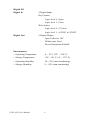
Product Warranty (2 years)
Advantech warrants to you, the original purchaser, that each of its products will be free from defects in materials and workmanship for two years
from the date of purchase.
This warranty does not apply to any products which have been repaired or
altered by persons other than repair personnel authorized by Advantech,
or which have been subject to misuse, abuse, accident or improper installation. Advantech assumes no liability under the terms of this warranty as
a consequence of such events.
Because of Advantech’s high quality-control standards and rigorous testing, most of our customers never need to use our repair service. If an
Advantech product is defective, it will be repaired or replaced at no
charge during the warranty period. For out-of-warranty repairs, you will
be billed according to the cost of replacement materials, service time and
freight. Please consult your dealer for more details.
If you think you have a defective product, follow these steps:
1.
Collect all the information about the problem encountered. (For
example, CPU speed, Advantech products used, other hardware
and software used, etc.) Note anything abnormal and list any
onscreen messages you get when the problem occurs.
2.
Call your dealer and describe the problem. Please have your manual, product, and any helpful information readily available.
3.
If your product is diagnosed as defective, obtain an RMA (return
merchandize authorization) number from your dealer. This allows
us to process your return more quickly.
4.
Carefully pack the defective product, a fully-completed Repair and
Replacement Order Card and a photocopy proof of purchase date
(such as your sales receipt) in a shippable container. A product
returned without proof of the purchase date is not eligible for warranty service.
5.
Write the RMA number visibly on the outside of the package and
ship it prepaid to your dealer.
iii
Declaration of Conformity
CE
This product has passed the CE test for environmental specifications
when shielded cables are used for external wiring. We recommend the use
of shielded cables. This kind of cable is available from Advantech. Please
contact your local supplier for ordering information.
FCC Class A
Note: This equipment has been tested and found to comply with the limits
for a Class A digital device, pursuant to part 15 of the FCC Rules. These
limits are designed to provide reasonable protection against harmful
interference when the equipment is operated in a commercial environment. This equipment generates, uses, and can radiate radio frequency
energy and, if not installed and used in accordance with the instruction
manual, may cause harmful interference to radio communications. Operation of this equipment in a residential area is likely to cause harmful interference in which case the user will be required to correct the interference
at his own expense.
Technical Support and Assistance
Step 1. Visit the Advantech web site at www.advantech.com/support
where you can find the latest information about the product.
Step 2. Contact your distributor, sales representative, or Advantech's customer service center for technical support if you need additional
assistance. Please have the following information ready before
you call:
- Product name and serial number
- Description of your peripheral attachments
- Description of your software (operating system, version, application software, etc.)
- A complete description of the problem
- The exact wording of any error messages
UNO-1019 User Manual
iv
Safety Instructions
1.
Read these safety instructions carefully.
2.
Keep this User's Manual for later reference.
3.
Disconnect this equipment from any AC outlet before cleaning.
Use a damp cloth. Do not use liquid or spray detergents for cleaning.
4.
For plug-in equipment, the power outlet socket must be located
near the equipment and must be easily accessible.
5.
Keep this equipment away from humidity.
6.
Put this equipment on a reliable surface during installation. Dropping it or letting it fall may cause damage.
7.
The openings on the enclosure are for air convection. Protect the
equipment from overheating. DO NOT COVER THE OPENINGS.
8.
Make sure the voltage of the power source is correct before connecting the equipment to the power outlet.
9.
Position the power cord so that people cannot step on it. Do not
place anything over the power cord.
10.
All cautions and warnings on the equipment should be noted.
11.
If the equipment is not used for a long time, disconnect it from the
power source to avoid damage by transient overvoltage.
12.
Never pour any liquid into an opening. This may cause fire or electrical shock.
13.
Never open the equipment. For safety reasons, the equipment
should be opened only by qualified service personnel.
14.
If one of the following situations arises, get the equipment checked
by service personnel:
a. The power cord or plug is damaged.
b. Liquid has penetrated into the equipment.
c. The equipment has been exposed to moisture.
d. The equipment does not work well, or you cannot get it to work
according to the user's manual.
e. The equipment has been dropped and damaged.
f. The equipment has obvious signs of breakage.
15.
DO NOT LEAVE THIS EQUIPMENT IN AN ENVIRONMENT
WHERE THE STORAGE TEMPERATURE MAY GO BELOW v
20° C (-4° F) OR ABOVE 60° C (140° F). THIS COULD DAMAGE THE EQUIPMENT. THE EQUIPMENT SHOULD BE IN A
CONTROLLED ENVIRONMENT.
16.
CAUTION: DANGER OF EXPLOSION IF BATTERY IS
INCORRECTLY REPLACED. REPLACE ONLY WITH THE
SAME OR EQUIVALENT TYPE RECOMMENDED BY THE
MANUFACTURER, DISCARD USED BATTERIES ACCORDING TO THE MANUFACTURER'S INSTRUCTIONS.
The sound pressure level at the operator's position according to IEC 7041:1982 is no more than 70 dB (A).
DISCLAIMER: This set of instructions is given according to IEC 704-1.
Advantech disclaims all responsibility for the accuracy of any statements
contained herein.
Safety Precaution - Static Electricity
Follow these simple precautions to protect yourself from harm and the
products from damage.
1.
To avoid electrical shock, always disconnect the power from your
PC chassis before you work on it. Don't touch any components on
the CPU card or other cards while the PC is on.
2.
Disconnect power before making any configuration changes. The
sudden rush of power as you connect a jumper or install a card may
damage sensitive electronic components.
UNO-1019 User Manual
vi
Contents
Chapter
1 Overview .......................................................... 2
1.1
1.2
1.3
1.4
Chapter
Introduction ....................................................................... 2
Features ............................................................................ 2
Hardware Specifications .................................................. 3
Chassis Dimensions.......................................................... 5
Figure 1.1:UNO-1019 Top View Dimensions ............... 5
Figure 1.2:UNO-1019 Side View Dimensions .............. 5
Figure 1.3:UNO-1019 Front View Dimensions ............ 6
Figure 1.4:UNO-1019 Bottom View Dimensions ......... 6
2 Installation ....................................................... 8
2.1
Overview ........................................................................... 8
2.2
LEDs.................................................................................. 9
2.3
2.4
Network Connections........................................................ 9
Serial Connections........................................................... 10
Figure 2.1:UNO-1019 Overview ................................... 8
Table 2.1:UNO-1019 LED Definitions ......................... 9
2.4.1
2.4.2
2.4.3
2.5
Power Connections.......................................................... 13
2.6
Digital Input/Output ........................................................ 14
2.7
2.8
CompactFlash.................................................................. 16
Mounting ......................................................................... 17
Figure 2.4:Power Pin Assignments .............................. 13
Figure 2.5:Digital I/O Pin Assignments ...................... 14
Figure 2.6:Digital Input Connection (Dry Contact) ..... 15
Figure 2.7:Digital Input Connection (Wet Contact) .... 15
Figure 2.8:Digital Output Connections (Wet Contact) 16
2.8.1
2.8.2
Chapter
Panel Mounting ............................................................ 17
Figure 2.9:Combine the Metal Mounting Kit .............. 17
Figure 2.10:Attach UNO-1019 to the Wall ................ 18
DIN-rail Mounting ....................................................... 19
Figure 2.11:Installation to DIN-rail Step 1 .................. 19
Figure 2.12:Installation to DIN -rail Step 2 ................. 20
Figure 2.13:Installation to DIN-rail Step 3 .................. 21
3 Initial Setup.................................................... 24
3.1
Chapter
Serial Type Selection ................................................... 10
Figure 2.2:COM3 & COM4 Serial Selection .............. 10
Enable Mode ................................................................ 11
Terminal Resistor ......................................................... 11
Figure 2.3: COM3& 4 Terminal Resistors (JP8& 10) . 11
Initial Procedure ............................................................. 24
4 Advanced Applications ................................. 32
4.1
4.2
Inserting a CompactFlash Card ...................................... 32
ActiveSync Connection................................................... 32
vii
Table of Contents
4.3
4.4
4.5
4.6
4.7
Remote Access Server Configuration ............................. 42
Autorun Configuration Note ........................................... 51
Application Development Procedure .............................. 55
4.5.1
4.5.2
4.5.3
Application Development Procedure ........................... 55
Watchdog Timer .......................................................... 57
DIO, LED and Buzzer ................................................. 63
Saving Your Settings...................................................... 72
UNO-1019 Network Administration User Guide .......... 72
4.7.1
4.7.2
4.7.3
4.7.4
4.7.5
UNO-1019 User Manual
Network Administration ............................................. 73
File Server .................................................................... 81
FTP Server ................................................................... 85
Telnet Server ................................................................ 89
Restart Network ........................................................... 90
viii
CHAPTER
1
2
Overview
This chapter gives background information on the UNO-1019. It shows you
the UNO-1019 overview and specifications.
Sections include:
• Introduction
• Features
• Hardware Specifications
• Safety Precautions
• Chassis Dimensions
Chapter 1 Overview
1.1 Introduction
Advantech’s UNO-1019 is a RISC-grade embedded platform that offers 2
LAN, 4 serial port and 4 Digital input and output to fulfill user’s I/O
device expansion. For data storage, UNO-1019 also provides a Compact
Flash for data storage.
UNO-1019 comes with a Windows CE.NET OS offering a pre-build
image on board. Microsoft Windows CE is a compact, highly efficient,
real-time operating system designed for embedded systems.
UNO-1019 could operate well under 0 ~ 70° C, its small size and light
weight could fit in industrial robust environment.
With these advantage, UNO-1019 is suitable for communication gateway
for converting communication protocol, IO control and data storage.
UNO-1019 is a perfect embedded ready platform that can shorten your
development time and offer a rich networking interface to fulfill your
diverse requirements.
1.2 Features
•
Intel XScale PXA-255 200 MHZ Processor
•
64 MB SDRAM on board, 16 MB Flash
•
2 RS-232, 2 RS-232/422/485 serial ports
•
Dual 10/100 Mbps Ethernet
•
1 compact flash for data storage
•
4 channel Digital input and output
•
3 channel LED for user define
•
Ready platform for WinCE.NET build in flash
•
Included remote display for easy configuration
•
Fanless design for reliable system
•
Compact size and light weight
•
0 ~ 70° C wide range operation
•
DIN-rail and wall mounting
•
Optional serial isolation protection
UNO-1019 User Manual
2
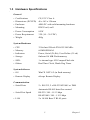
1.3 Hardware Specifications
General
• Certifications
CE, FCC Class A
• Dimensions (W*H*D)
46 x 162 x 126 mm
• Enclosure
ABS+PC with solid mounting hardware
• Mounting
DIN35 rail, wall
• Power Consumption
8.5W
• Power Requirement
3 W (10 ~ 30 VDC)
• Weight
400g
System Hardware
• CPU
32 bit Intel XScale PXA255 200 MHz
• Memory
64 MB SDRAM
• Indicators
Power, Serial (Tx,Rx), User Define (3 Led)
• Storage
Onboard 16 MB Flash memory
• SSD:
1 x internal type I/II CompactFlash slot
• Others
Real Time Clock, Watch Dog Timer
System Software
• OS
WinCE .NET 4.2 (in flash memory)
• Remote Display
uScope Remote Display
Communication
• Serial Ports
2 × RS-232, 2 x RS-232/422/485 w/ DB9
Automatic RS-485 data flow control
• Serial Port Speed
RS-232: 300 ~ 115.2 kbps
RS-422/485: 300 ~ 115.2 kbps
• LAN
2 x 10/100 Base-T RJ-45 ports
3
Chapter 1
Digital I/O
Digital In
2 Digital Input
Dry Contact
Logic level 0 : Open
Logic level 1 : Close
Wet Contect
Logic level 0: +3V max
Logic level 1: +10VDC to 30VDC
Digital Out
2 Digital Output
Open Collect to 30V
200mA max Load
Power Dissipation 450mW
Environment
• Operating Temperature
0 ~ 70° C (32° ~ 158° F)
• Storage Temperature
-20° ~ 80° C (-4° ~ 176° F)
• Operating Humidity
20 ~ 95% (non-condensing)
• Storage Humidity
0 ~ 95% (non-condensing)
UNO-1019 User Manual
4
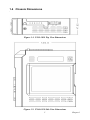
1.4 Chassis Dimensions
Figure 1.1: UNO-1019 Top View Dimensions
Figure 1.2: UNO-1019 Side View Dimensions
5
Chapter 1
Figure 1.3: UNO-1019 Front View Dimensions
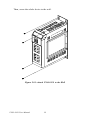
Figure 1.4: UNO-1019 Bottom View Dimensions
UNO-1019 User Manual
6
CHAPTER
2
2
Installation
In this chapter, you will be given an
overview of the UNO-1019 hardware
installation procedures.
Sections include:
• Overview:
• LED
• Network Connections
• Serial Connections
• Power Connections
• Digital Input/Output
• CompactFlash
• Mounting
Chapter 2 Installation
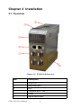
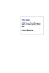
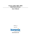
2.1 Overview
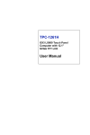
Figure 2.1: UNO-1019 Overview
Item
Description
1
Serial Port
2
Networking port
3
LED
4
CompactFlash™ slot
5
Power
6
Digital input/output
UNO-1019 User Manual
8
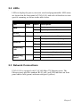
2.2 LEDs
LEDs to display the power, network, serial and programmable LED status
are located on the front panel of UNO-1019, and each of them has its own
specific meaning, as shown in the table below.
Table 2.1: UNO-1019 LED Definitions
LED
Color
Status
Description
PWR
RED
On
System power is on
Off
System power is off
D1~D3
Green
User programmable
Serial TX
Yellow
On
Serial port is transmitting data
Off
Serial port is not transmitting data
Serial RX
Green
Networking
Link
Green
Networking
Speed
Yellow
On
Serial port is receiving data
Off
Serial port is not receiving data
On
Connected to network
Off
Not connected to network
Flash
Data is transmitting/receiving
On
Link to 100 Mbps network
Off
Link to 10 Mbps network
2.3 Network Connections
UNO-1019 is equipped with 2 10/100 Mbps TX Ethernet ports. The
Ethernet ports provide standard RJ-45 jack, and LED indicator on front
panel shows link (green) and network speed (yellow).
9
Chapter 2
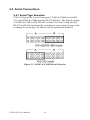
2.4 Serial Connections
2.4.1 Serial Type Selection
UNO-1019 provides 4 serial Com ports, COM1 & COM2 provide RS232, and COM3 & COM4 provide RS-232/422/485. The default settings
of COM3 & COM4 is RS-422/485, and the UNO-1019 could identify
RS-422 or RS-485 automatically according to your wiring. If users want
to change the serial type, the chassis can be opened and modified.
Figure 2.2: COM3 & COM4 Serial Selection
UNO-1019 User Manual
10
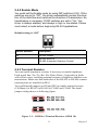
2.4.2 Enable Mode
You could set the Enable mode by using DIP switches (S10). If the
switches are set to "Off", the driver automatically senses the direction of the data flow and switches the direction of transmission. No
handshaking is necessary. If DIP switches are set to "On," the
driver is always enabled, and always in high or low status. Please
must select a mode before beginning RS-422 applications.
Default setting is “Off”
Switch position
Description
On
RS-422 master
Off
RS-422 slave or
RS-485 Automatic Direction Control
2.4.3 Terminal Resistor
You can install terminator resistors if necessary to match impedance.
Each signal line (Tx+/Tx-/Rx+/Rx-/Data+/Data-). Especially in fields
with electric noise, installing terminal resistors is helpful to stabilize communications. Make sure that both sides of the RS-422 or RS-485 communication ports are installed on BUS.
You could install jumpers on JP8 and JP10 to enable terminal resistor
(120Ohms) for RS-422 or RS-485 of COM3 and COM4. The detail
jumper setting shows as following figure.
Figure 2.3: COM3& 4 Terminal Resistors (JP8& 10)
11
Chapter 2
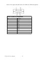
Refer to the figure and table below for COM1 & COM2 descriptions.
COM1 & COM2 Pin Assignments
Pin
RS-232
1
DCD
2
RxD
3
TxD
4
DTR
5
GND
6
DSR
7
RTS
8
CTS
9
RI
UNO-1019 User Manual
12
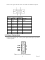
Refer to the figure and table below for COM3 & COM4 descriptions.
COM3 & COM4 Pin Assignments
Pin
RS-232
RS-422
RS-485
1
DCD
TxD-
Data-
2
RxD
TxD+
Data+
3
TxD
RxD+
-
4
DTR
RxD-
-
5
GND
GND
GND
6
DSR
-
-
7
RTS
-
-
8
CTS
-
-
9
RI
-
-
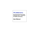
2.5 Power Connections
UNO-1019 supports +10 ~ 30 VDC power inputs, detail power pin shows
as below picture.
Figure 2.4: Power Pin Assignments
13
Chapter 2
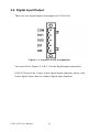
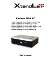
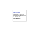
2.6 Digital Input/Output
There are two digital inputs and outputs for UNO-1019.
Figure 2.5: Digital I/O Pin Assignments
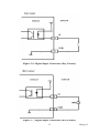
You can refer to Figures 2.6 & 2.7 for the digital input connection.
UNO-1019 provides 2 ways to use digital inputs function, please refer
below figure shows how to connect digital input function.
UNO-1019 User Manual
14
Figure 2.6: Digital Input Connection (Dry Contact)
Figure 2.7: Digital Input Connection (Wet Contact)
15
Chapter 2
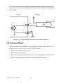
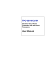
UNO-1019 also provides digital outputs connection, please refer below
figure shows how to connect digital output function.(The default DO status is high)
Figure 2.8: Digital Output Connections (Wet Contact)
2.7 CompactFlash
The procedure for installing a CompactFlash card into the UNO-1019 is
detailed below, please follow these steps carefully
1. Make sure system power is off
2. Remove the power cord
3. Remove CompactFlash the card door on the top panel of UNO-1019
4. Plug a CompactFlash card into a CompactFlash card slot.
UNO-1019 User Manual
16
2.8 Mounting
UNO-1019 supports two different mounting methods: Panel & DIN-rail.
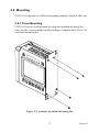
2.8.1 Panel Mounting
UNO-1019 can be wall mounted by using the included mounting kit.
First, use the screws included in the package to combine the UNO-1019
and metal mounting kit.
Figure 2.9: Combine the Metal Mounting Kit
17
Chapter 2
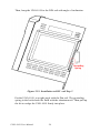
Then, screw the whole device to the wall.
Figure 2.10: Attach UNO-1019 to the Wall
UNO-1019 User Manual
18
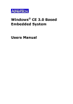
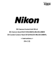
2.8.2 DIN-rail Mounting
You can also mount UNO-1019 on a standard DIN-rail by below steps.
First, pull down the kit in the back of UNO-1019
Figure 2.11: Installation to DIN-rail Step 1
19
Chapter 2
Then, hang the UNO-1019 to the DIN-rail with angle of inclination.
Figure 2.12: Installation to DIN -rail Step 2
Put the UNO-1019 at a right angle with the Din-rail. The grounding
spring in the back should be flush with the aluminum rail. Then pull up
the kit to wedge the UNO-1019 firmly into place.
UNO-1019 User Manual
20
Figure 2.13: Installation to DIN-rail Step 3
21
Chapter 2
UNO-1019 User Manual
22
CHAPTER
3
2
Initial Setup
This chapter shows how to initialize the
UNO-1019, sections include:
Sections include:
• Initial Procedure
• Configure UNO-1019
Chapter 3 Initial Setup
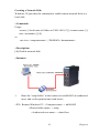
3.1 Initial Procedure
The UNO-1019 offers an easy setup feature: It takes four easy steps for
your initial setup before use. Take out the UNO-1019 from the package
and follow the steps below for initial setup:
1.
Connect all peripheral devices, such as RJ-45 connector of Ethernet
connection, RS-232 (RJ-48 connector) and RS-485 connectors.
2.
Connect the power cord to the UNO-1019 and plug the other end of
the cord into the power outlet, and then UNO-1019 boots up immediately. (IP Default setting : LAN1 is 10.0.0.1, LAN2 is 10.0.0.2)
3.
The UNO-1019 default IP is set as 10.0.0.1. Please set the IP of
your host computer to be static IP : 10.0.0.XXX for connection
with UNO-1019.
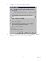
4.
Using the uScope tool to re-configure the IP of UNO-1019 to meet
your network configuration. The path of uScope Remote Display
Tool in UNO-1019 CD is “\uScope Remote Display
Tool\uScope.EXE “.
uScope Remote Display Tool
This tool works only with Ethernet connection. it's requires both of your
computer and the UNO-1019 has same Subnet Mask. The default IP
address for LAN1 is : 10.0.0.1 and the default Subnet mask is:
255.255.255.0. So you can set your computer IP address to 10.0.0.3 and
set the Subnet mask to 255.255.255.0.
UNO-1019 User Manual
24
*actually you can set any IP address that other than 10.0.0.1 and 10.0.0.2
from 10.0.0.3 to 10.0.0.255 . If you connected you computer and UNO1019 to a router, don't set your computer IP address the same as the
Router's.
Connect UNO-1019 with your computer by using a crossover Ethernet
cable. Or connect both UNO-1019 and your computer into a hub.
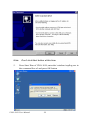
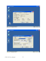
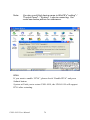
After UNO-1019 boot up, it will broadcast it's IP to the network. uScope
Remote Display tool running on you computer will detect the UDP message that send out by UNO-1019 and show the device name and IP in it's
device list. You can select and connect to the device (UNO-1019) in the
list as you want.
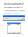
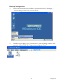
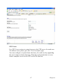
Double Click the uScope icon in configuration computer:
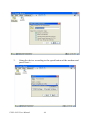
Click the “Show List” bottom :
25
Chapter 3
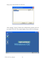
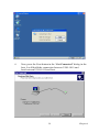
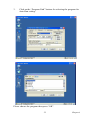
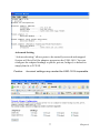
Choose the connected device in the list :
After clicking “Connect” bottom, the configuration computer will connect with UNO-1019. The remote display screen will be as following :
UNO-1019 User Manual
26
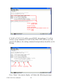
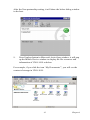
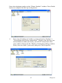
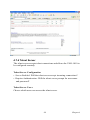
Please go to the “Command Prompt” for network IP setting
User can use “ipchange” command for IP change setting in command
prompt mode. Please type “ipchange /?” for command reference.
27
Chapter 3
If LAN1 of UNO-1019 will be set as DHCP,, the ipchange 1/1 will be
used as set up command. If LAN2 of the UNO-1019 will be set as the
specific IP address, the setting command and procedure should be as following :
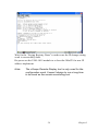
Press “Enter”, the remote display will show the following message.
UNO-1019 User Manual
28
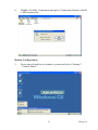
Wait for the “Saving Registry Done” to make sure the IP change setting
work is successfully done.
Re-power on the UNO-1019 module to re-boot the WinCE for new IP
address implement.
Note:
The uScope Remote Display tool is only used for the
configuration work. It wasn’t design to run a long time
to be used as the remote monitoring tool.
29
Chapter 3
UNO-1019 User Manual
30
CHAPTER
4
2
Advanced Applications
This Chapter will provide detailed
explanations of the UNO-1019’s
Advanced Applications
Sections include:
• Inserting a CompactFlash Card
• ActiveSync Connection
• Remote Access Configuration
• Autorun Configuration
• Application Development Procedure
• Saving Your Settings
• Network Administration User Guide
Chapter 4 Advanced Applications
4.1 Inserting a CompactFlash Card
The procedure for installing a CompactFlash card into the UNO-1019 is
as follows, and please follows these steps carefully.
1.
Remove the power connector to power off the UNO-1019
2.
Remove the CF slot cover.
3.
Plug a CompactFlash card with user's OS and application
program into a CompactFlash card slot on board.
4.
Plug in the CD slot cover for protecting the CF card.
5.
Connector the power connector to re-power on the UNO-1019
Note:
How to update the WinCE.NET 4.2 Image for UNO-1019?
Please follow the above steps to plug in the CF card with image
(the image file is put in the path:\UNO-1019\Image of UNO1019 CD. please copy the image file from CD to CF card and
please be noticed the format of the CF card must be FAT16)
then wait for 5 minutes for rebooting the UNO-1019 with new
image.
4.2 ActiveSync Connection
• Using a null-modem cable connect UNO-1019 COM1 with one of
COM port on your computer
• Install Microsoft ActiveSync software on your computer and make the
serial port you want connect with UNO-1019 available for ActiveSync
(see ActiveSync help for details).
Note:
UNO-1019 will use 115200 as it default BaudRate for the
ActiveSync connection. If your ActiveSync program never
accept a connection at this BaudRate before, you' might get a
timeout. Since it needs to scan from low to high BaudRate, if
that takes too long, UNO-1019 will stop trying connect to your
computer. So, its better to use another CE device which has a
display to connect to you Desktop through ActiveSync at
19200 BaudRate first. Thus ActieSync on your desktop PC will
remember this Baud Rate, and next time when UNO-1019 try
to connect to it at this Baud Rate, it'll connect easily.
UNO-1019 User Manual
32
ActiveSync Connection
The tool is used for the application program on-line programming/debug
requirement. User has to install the Microsoft ActiveSync program in
configuration computer first. For the detail operating procedure of
ActiveSync, please follow the steps by steps operating guide.
Step 1 : Setting Up ActiveSync in a Configuration Computer
1.
Insert UNO-1019 CD into the configuration computer.
2.
Install UNO-1019 Software Development Kit for eVC++ from
below path: \UNO-1019\SDK
3.
Install Microsoft ActiveSync 4.1 from below path: \ActiveSync
4.
Please connect the ActiveSync cable (Null Modem cable, Advantech part no. : 1703093000) to COM1 of UNO-1019 and the COM
port of configuration computer for ActiveSync communication.
Step 2 : Connect the UNO-1019 via uScope through Ethernet.
Step 3 : Configure COM1 of UNO-1019
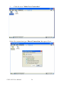
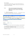
Press Start of task bar of window system and select “Settings” / “Network and Dial-up Connections”.
33
Chapter 4
1.
Click the icon “Make New Connection”
Select the connection type: Direct Connection, then press Next
UNO-1019 User Manual
34
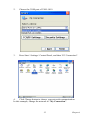
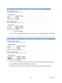
2.
Choose the COM port of UNO-1019.
3.
Press Start / Settings / Control Panel, and then “PC Connection”.
4.
Click Change button to choose your network communication.
In this example, change the network to “My Connection”.
35
Chapter 4
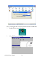
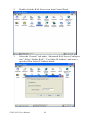
Step 4 : Setting Up the Communication Environment of the Host
1.
Double click the icon ActiveSync.
2.
Select File/Connection Settings
UNO-1019 User Manual
36
3.
Configure the connection settings as below.
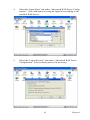
4.
After you configure the connection setting, it will show the below
dialog window when you press Get Connected
37
Chapter 4
Note:
5.
Don’t click Next button at this time.
Press Start/ Run of UNO-1019; enter the \windows\repllog.exe in
the command line of and press OK button
UNO-1019 User Manual
38
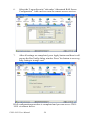
6.
Now, press the Next button in the “Get Connected” dialog in the
host. It will build the connection between UNO-1019 and
host.between UNO-1019 and host.
39
Chapter 4
7.
If the connection between UNO-1019 and the host has been
established, you will see below message in UNO-1019.
8.
If the connection between UNO-1019 and the host has been
established, you will see below message in the host.
Select No, then press Next button.
UNO-1019 User Manual
40
After the New partnership setting, it will show the below dialog window
in the host.
9.
Press Explore button in Microsoft ActiveSync window, it will pop
up the Mobile Device window to display the file resources and
information of UNO-1019 as below:
For example, if you click the icon “My Documents’”, you will see the
content of storage in UNO-1019.
41
Chapter 4
Begin Transferring Files from the PC to UNO-1019
Double click “My Computer” in “Mobile Device” for file translation.
4.3 Remote Access Server Configuration
UNO-1019 provides “Remote Access Services” which offers the possibilities for remote network and user to have TCP/IP access local mail servers, access to database, web servers or other Intranet services.
The following description introduces how to set the dial-up and dial-in
configuration.
UNO-1019 User Manual
42
Dial-up Configuration
1.
Press start of task bar of window system and select “Settings” /
“Networking and Dial-up Connections”
2.
Double click “Make New Connection”, then a dialog window will
pop out. Select Dial-Up Connection and press Next >.
43
Chapter 4
3.
Setup the device according to the specification of the modem and
press Next >.
UNO-1019 User Manual
44
Enter the telephone number in the “Phone Number” window. Press Finish
button to complete the dial-up configuration.
4.
Press start of task bar of window system and select “Setting” ‡
“Networking and Dial-up connections”. Double click the new connection that you made previously (it is RAS Connection in this
case), and it will pop out the “Dial-Up Connection” dialog window.
Enter your user name / password, then press Dial Properties.
45
Chapter 4
5.
Note:
Press Dialing Patterns button in the Dialing Properties window.
Edit the dialing pattern for each type of call to change how the
phone is dialed.
Country/Region Code, please enter “E” or “e”
Area Code, please enter “F” or “f”
Number, please enter “G” or “g”
UNO-1019 User Manual
46
6.
Double click My Connection and press Connection button to build
a PPP connection.
Dial-in Configuration
1.
Press start of task bar of window system and select “Setting” /
“Control Panel”.
47
Chapter 4
2.
Double click the RAS Server icon from Control Panel.
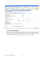
3.
Select the “General” tab under “Advantech RAS Server Configuration”. Select “Enable RAS”, “Use Static IP Address” and enter a
specified IP in Static IP Address blank.
UNO-1019 User Manual
48
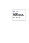
4.
Select the “Input Lines” tab under “Advantech RAS Server Configuration”. Click Add button to setup the input line according to the
available RAS device.
5.
Select the “Logon Security” tab under “Advantech RAS Server
Configuration”. Select security protocol if necessary.
49
Chapter 4
6.
Select the “Logon Security” tab under “Advantech RAS Server
Configuration”. Add a new account for remote access services.
7.
After all settings are completed, press Apply button and then it will
pop up the RasConfig dialog window. Press Yes button to save registry setting to storage card.
RAS configuration procedure is completed and you can access UNO1019 via remote device.
UNO-1019 User Manual
50
4.4 Autorun Configuration Note
This document introduces how to execute applications automatically
when you boot UNO-1019 up.
Autorun Configuration Procedure
1.
Execute the “UNO Configuration Utility”
2.
Go to the “Misc” page in UNO Configuration Utility.
51
Chapter 4
UNO-1019 User Manual
52
3.
Click on the “Program Path” bottom for selecting the program for
Auto-Run setting..
Please choose the program then press “OK”.
53
Chapter 4
4.
Click on the “Add” bottom to set the program for Auto-Run action.
The UNO Configuration Utility will add the selected program in AutoRun requirement. Please press “OK” to finish the configuration.
UNO-1019 User Manual
54
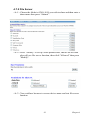
4.5 Application Development Procedure
UNO-1019 provides Software Development Kit (SDK) and a built-in
runtime library; you can use your existing windows-based programming
skills to develop applications easily and rapidly through those tools. This
document introduces how to develop custom application step by step.
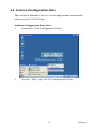
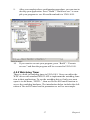
4.5.1 Application Development Procedure
1.
Install Microsoft eMbedded Visual C++ V4.00 with Service Pack 2
The Microsoft eMbedded Visual C++ tool is a desktop development environment for creating applications and system components for Windows CE .NET-powered devices. This version
features new capabilities such as C++ exception handling, Run
Time Type Information (RTTI), and a plethora of new debugger
functionalities. Before you begin to develop your application, you
must install Microsoft eMbedded Visual C++ first.
2.
Insert UNO-1019 CD into the CD-ROM in the host PC.
3.
Install UNO-1019 Software Development Kit for eMbedded Visual
C++ from below path:
\UNO-1019\SDK
4.
Install Microsoft ActiveSync 4.1 from below path:
\ActiveSync
5.
Build the connection between the host and UNO-1019 via ActiveSync. Further information about ActiveSync, please refer to
“ActiveSync Connection”.
6.
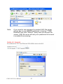
Execute eMbedded Visual C++.
7.
Select “File” ‡ “New” to open a new project. Select your project
type in the left blank of window and enter the new project name /
location in the right side of window. Please note that CPU type
must select Win32 (WCE ARMV4I).
55
Chapter 4
8.
Select “UNO-1019” in the main window of Visual C++ .
UNO-1019 User Manual
56
9.
After you complete above configuration procedure, you can start to
develop your application. Press “Build”/ “Build xxx.exe” to compile your program to .exe file and download it to UNO-1019.
10.
If you want to execute your program, press “Build” / “Execute
xxx.exe” and then the program will be executed in UNO-1019.
4.5.2 Watchdog Timer
There is a built-in watchdog timer in UNO-1019. Users can utilize the
WDT driver with standard WIN32 API to implement the watchdog function in their applications. To use the watchdog driver, firstly user must
open it via the name, “WDT1:”, then use DeviceIOControl function to
access the watchdog hardware. The introduction below includes the definition of DeviceIOControl and its parameters as well as an example.
57
Chapter 4
How to Use the Control Code
There are 6 control codes for the operation codes in the WDT driver.
1. IOCTL _WDT_ENABLE:
Enable the Watchdog timer on your application. By default, if the Watchdog timer is enabled, the WDT driver will automatically reload the timeout counter after a specified period and your application does not need to
trigger the strobe periodically for masking the timeout, unless use
IOCTL_WDT_REBOOT to stop this automatic strobe triggering.
lpInBuffer : unused.
nInBufferSize: unused.
lpOutBuffer: unused.
nOutBufferSize: unused.
2. IOCTL _WDT_DISABLE:
Disable the Watchdog time on your application.
lpInBuffer : unsed.
nInBufferSize: unused.
lpOutBuffer: unused.
nOutBufferSize: unused.
3. IOCTL_WDT_STROBE:
Trigger strobe signal to reload watchdog timeout counter. If your application uses IOCTL_WDT_ENABLE to enable the Watchdog first and then
sends IOCTL_WDT_REBOOT to the WDT driver, your application must
trigger the Watchdog once during the Watchdog timer period. If your
application has not triggered at the specified period, the device will
reboot automatically.
lpInBuffer: unused.
nInBufferSize: unused.
lpOutBuffer: unused.
nOutBufferSize: unused.
UNO-1019 User Manual
58
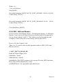
4. IOCTL_WDT_GETTIMEOUT:
Get the Watchdog timeout value.
lpInBuffer: unused.
nInBufferSize: unused.
lpOutBuffer: The DWORD pointer to your Watchdog timeout setting.
The Watchdog timeout setting is just a number. 0 means 2 seconds, 1
means 5 seconds, 2 means 10 seconds, 3 means 15 seconds, 4 means 30
seconds, 5 means 45 seconds, 6 means 60 seconds, 7 means 120 seconds,
8 means 300 seconds, 9 means 600 seconds, 10 means 900 seconds, others means the maximum 1140 seconds. The default setting is 5 seconds.
nOutBufferSize: unused.
5. IOCTL_WDT_SETTIMEOUT:
Set the Watchdog timeout value.
lpInBuffer : The DWORD pointer to your Watchdog timeout setting. The
Watchdog timeout setting is just a number. 0 means 2 seconds, 1 means 5
seconds, 2 means 10 seconds, 3 means 15 seconds, 4 means 30 seconds, 5
means 45 seconds, 6 means 60 seconds, 7 means 120 seconds, 8 means
300 seconds, 9 means 600 seconds, 10 means 900 seconds, others means
the maximum 1140 seconds. The default setting is 5 seconds.
nInBufferSize:.unused.
lpOutBuffer: unused.
nOutBufferSize: unused.
6. IOCTL_WDT_REBOOT:
If you want your application to trigger the Watchdog by itself, please use
IOCTL_WDT_REBOOT to notify the WDT driver. Otherwise, the WDT
will trigger itself automatically.
lpInBuffer :unused.
nInBufferSize: unused.
lpOutBuffer: unused.
nOutBufferSize: unused.
59
Chapter 4
DeviceIOControl
This function sends a control code directly to a specified device driver,
causing the corresponding device to perform the specified operation.
BOOL DeviceIoControl(
HANDLE hDevice,
DWORD dwIoControlCode,
LPVOID lpInBuffer,
DWORD nInBufferSize,
LPVOID lpOutBuffer,
DWORD nOutBufferSize,
LPDWORD lpBytesReturned,
LPOVERLAPPED lpOverlapped );
Parameters:
. hDevice
[in] Handle to the device that is to perform the operation. Call the CreateFile function to obtain a device handle.
. dwIoControlCode
[in] Specifies the control code for the operation. This value identifies the
specific operation to be performed and the type of device on which the
operation is to be performed. No specific values are defined for the dwIoControlCode parameter. However, the writer of a custom device driver
can define IOCTL_XXXX control codes, per the CTL_CODE macro.
These control codes can then be advertised, and an application can use
these control codes with DeviceIoControl to perform driver specific functions.
. lpInBuffer
[in] Long pointer to a buffer that contains the data required to perform the
operation. This parameter can be NULL if the dwIoControlCode parameter specifies an operation that does not require input data.
. nInBufferSize
[in] Size, in bytes, of the buffer pointed to by lpInBuffer.
. lpOutBuffer
UNO-1019 User Manual
60
[out] Long pointer to a buffer that receives the output data for the operation. This parameter can be NULL if the dwIoControlCode parameter
specifies an operation that does not produce output data.
. nOutBufferSize
[in] Size, in bytes, of the buffer pointed to by lpOutBuffer.
. lpBytesReturned
[out] Long pointer to a variable that receives the size, in bytes, of the data
stored into the buffer pointed to by lpOutBuffer. The lpBytesReturned
parameter cannot be NULL. Even when an operation produces no output
data, and lpOutBuffer can be NULL, the DeviceIoControl function makes
use of the variable pointed to bylpBytesReturned. After such an operation, the value of the variable is without meaning.
. lpOverlapped
[in] Ignored; set to NULL.
. Return Values
Nonzero indicates success. Zero indicates failure. To get extended error
information, call GetLastError.
Examples
#define IOCTL_WDT_ENABLE
CTL_CODE(FILE_DEVICE_UNKNOWN, 0x900,
METHOD_BUFFERED, FILE_ANY_ACCESS)
#define IOCTL_WDT_DISABLE
CTL_CODE(FILE_DEVICE_UNKNOWN, 0x901,
METHOD_BUFFERED, FILE_ANY_ACCESS)
#define IOCTL_WDT_STROBE
CTL_CODE(FILE_DEVICE_UNKNOWN, 0x902,
METHOD_BUFFERED, FILE_ANY_ACCESS)
#define IOCTL_WDT_GET_TIMEOUT
CTL_CODE(FILE_DEVICE_UNKNOWN, 0x903,
METHOD_BUFFERED, FILE_ANY_ACCESS)
#define IOCTL_WDT_SET_TIMEOUT
CTL_CODE(FILE_DEVICE_UNKNOWN, 0x904,
METHOD_BUFFERED, FILE_ANY_ACCESS)
61
Chapter 4
#define IOCTL_WDT_REBOOT
CTL_CODE(FILE_DEVICE_UNKNOWN, 0x905,
METHOD_BUFFERED, FILE_ANY_ACCESS)
HANDLE m_hWDT=NULL;
TCHAR szClassName[60];
// assign the WDT driver name
wsprintf(szClassName, TEXT("WDT1:"));
// Open the WDT driver
m_hWDT = CreateFile(szClassName,
GENERIC_READ|GENERIC_WRITE, 0, NULL, OPEN_EXISTING,
FILE_ATTRIBUTE_NORMAL, NULL);
if ( m_hWDT == INVALID_HANDLE_VALUE ) {
DebugMsg(CString("WDT driver fail"));
return;
}
DWORD dwTemp;
DWORD nIndex=2;
// Set the Watchdog Timer as 10 seconds. Number 2 means 10 seconds.
DeviceIoControl(m_hWDT, IOCTL_WDT_SET_TIMEOUT, &nIndex,
sizeof(nIndex), NULL, 0, &dwTemp, NULL);
// Enable the Watchdog timer
DeviceIoControl(m_hWDT, IOCTL_WDT_ENABLE, NULL, 0, NULL,
0, &dwTemp, NULL);
// Activate timeout reboot
DeviceIoControl(m_hWDT, IOCTL_WDT_REBOOT, NULL, 0, NULL,
0, &dwTemp, NULL);
UNO-1019 User Manual
62
While (1) {
// do your job here.
Sleep(8000);
DeviceIoControl(m_hWDT, IOCTL_WDT_STROBE, NULL,0, NULL,
0, &dwTemp, NULL);
}
DeviceIoControl(m_hWDT, IOCTL_WDT_DISABLE, NULL, , NULL,
0, &dwTemp, NULL);
CloseHandle(m_hWDT);
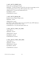
4.5.3 DIO, LED and Buzzer
UNO-1019 has 2 DI(Digital Input) , 2 DO(Digital Output), 3 LED and a
Buzzer. Users can access these resources via the built-in Advantech IO
Service driver named “ADV1:”.The follows are the descriptions and
examples of the usable DeviceIoControl codes in this driver:
How to Use the Control Code
There are 11 control codes for the operation codes in DIO, LED, and
Buzzer (driver).
1. ADV_IOCTL_READ_DI:
Read the Digital Input value.
lpInBuffer : unsed.
nInBufferSize: unused.
lpOutBuffer: The BYTE pointer to the current DI value. BIT0 indicates
DI_0 state; BIT1 indicates DI_1 state.
nOutBufferSize: User provided output buffer size.
63
Chapter 4
2. ADV_IOCTL_WRITE_DO:
Write value out the Digital Output.
lpInBuffer : The BYTE pointer to the DO value that is requesting to write
out. BIT0 indicates DO_0 state; BIT1 indicates DO_1 state.
nInBufferSize: User provided input buffer size.
lpOutBuffer: unsed.
nOutBufferSize: unsed.
3. ADV_IOCTL_READ_DO:
Read the written Digital Output value.
lpInBuffer : unsed.
nInBufferSize: unsed.
lpOutBuffer: The BYTE pointer to the current DO value. BIT0 indicates
DO_0 state; BIT1 indicates DO_1 state.
nOutBufferSize: User provided input buffer size.
4. ADV_IOCTL_TURN_ON_LED1:
Turn LED1 on.
lpInBuffer :unused.
nInBufferSize: unused.
lpOutBuffer: unused.
nOutBufferSize: unused.
5. ADV_IOCTL_TURN_OFF_LED1:
Turn LED1 off.
lpInBuffer :unused.
nInBufferSize: unused.
lpOutBuffer: unused.
nOutBufferSize: unused.
UNO-1019 User Manual
64
6. ADV_IOCTL_TURN_ON_LED2:
Turn LED2 on.
lpInBuffer :unused.
nInBufferSize: unused.
lpOutBuffer: unused.
nOutBufferSize: unused.
7. ADV_IOCTL_TURN_OFF_LED2:
Turn LED2 off.
lpInBuffer :unused.
nInBufferSize: unused.
lpOutBuffer: unused.
nOutBufferSize: unused.
8. ADV_IOCTL_TURN_ON_LED3:
Turn LED3 on.
lpInBuffer :unused.
nInBufferSize: unused.
lpOutBuffer: unused.
nOutBufferSize: unused.
9. ADV_IOCTL_TURN_OFF_LED3:
Turn LED3 off.
lpInBuffer :unused.
nInBufferSize: unused.
lpOutBuffer: unused.
nOutBufferSize: unused.
65
Chapter 4
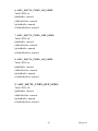
10. IOCTL_PLAY_BUZZER:
Make the buzzer start beeping.
lpInBuffer : The DWORD pointer to the number of mini-seconds to play.
nInBufferSize: User provided input buffer size.
lpOutBuffer: unsed.
nOutBufferSize: unsed.
11. IOCTL_STOP_BUZZER:
Stop the buzzer that is playing.
lpInBuffer :unused.
nInBufferSize: unused.
lpOutBuffer: unused.
nOutBufferSize: unused.
DeviceIOControl
This function sends a control code directly to a specified device driver,
causing the corresponding device to perform the specified operation.
BOOL DeviceIoControl(
HANDLE hDevice,
DWORD dwIoControlCode,
LPVOID lpInBuffer,
DWORD nInBufferSize,
LPVOID lpOutBuffer,
DWORD nOutBufferSize,
LPDWORD lpBytesReturned,
LPOVERLAPPED lpOverlapped );
UNO-1019 User Manual
66
Parameters:
. hDevice
[in] Handle to the device that is to perform the operation. Call the CreateFile function to obtain a device handle.
. dwIoControlCode
[in] Specifies the control code for the operation. This value identifies the
specific operation to be performed and the type of device on which the
operation is to be performed. No specific values are defined for the dwIoControlCode parameter. However, the writer of a custom device driver
can define IOCTL_XXXX control codes, per the CTL_CODE macro.
These control codes can then be advertised, and an application
can use these control codes with DeviceIoControl to perform driver specific functions.
. lpInBuffer
[in] Long pointer to a buffer that contains the data required to perform the
operation. This parameter can be NULL if the dwIoControlCode parameter specifies an operation that does not require input data.
. nInBufferSize
[in] Size, in bytes, of the buffer pointed to by lpInBuffer.
. lpOutBuffer
[out] Long pointer to a buffer that receives the output data for the operation. This parameter can be NULL if the dwIoControlCode parameter
specifies an operation that does not produce output data.
. nOutBufferSize
[in] Size, in bytes, of the buffer pointed to by lpOutBuffer.
. lpBytesReturned
[out] Long pointer to a variable that receives the size, in bytes, of the data
stored into the buffer pointed to by lpOutBuffer. The lpBytesReturned
parameter cannot be NULL. Even when an operation produces no output
data, and lpOutBuffer can be NULL, the DeviceIoControl function makes
use of the variable pointed to bylpBytesReturned. After such an operation, the value of the variable is without meaning.
. lpOverlapped
[in] Ignored; set to NULL.
. Return Values
67
Chapter 4
Nonzero indicates success. Zero indicates failure. To get extended error
information, call GetLastError.
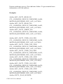
Examples
#define ADV_IOCTL_READ_DI
CTL_CODE(FILE_DEVICE_UNKNOWN, 0x900,
METHOD_BUFFERED, FILE_ANY_ACCESS)
#define ADV_IOCTL_READ_DO
CTL_CODE(FILE_DEVICE_UNKNOWN, 0x902,
METHOD_BUFFERED, FILE_ANY_ACCESS)
#define ADV_IOCTL_WRITE_DO
CTL_CODE(FILE_DEVICE_UNKNOWN, 0x904,
METHOD_BUFFERED, FILE_ANY_ACCESS)
#define ADV_IOCTL_TURN_ON_LED1
CTL_CODE(FILE_DEVICE_UNKNOWN, 0x930,
METHOD_BUFFERED, FILE_ANY_ACCESS)
#define ADV_IOCTL_TURN_OFF_LED1
CTL_CODE(FILE_DEVICE_UNKNOWN, 0x931,
METHOD_BUFFERED, FILE_ANY_ACCESS)
#define ADV_IOCTL_TURN_ON_LED2
CTL_CODE(FILE_DEVICE_UNKNOWN, 0x932,
METHOD_BUFFERED, FILE_ANY_ACCESS)
#define ADV_IOCTL_TURN_OFF_LED2
CTL_CODE(FILE_DEVICE_UNKNOWN, 0x933,
METHOD_BUFFERED, FILE_ANY_ACCESS)
#define ADV_IOCTL_TURN_ON_LED3
CTL_CODE(FILE_DEVICE_UNKNOWN, 0x934,
METHOD_BUFFERED, FILE_ANY_ACCESS)
#define ADV_IOCTL_TURN_OFF_LED3
CTL_CODE(FILE_DEVICE_UNKNOWN, 0x935,
METHOD_BUFFERED, FILE_ANY_ACCESS)
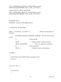
#define IOCTL_PLAY_BUZZER
UNO-1019 User Manual
68
CTL_CODE(FILE_DEVICE_UNKNOWN, 0x950,
METHOD_BUFFERED, FILE_ANY_ACCESS)
#define IOCTL_STOP_BUZZER
CTL_CODE(FILE_DEVICE_UNKNOWN, 0x951,
METHOD_BUFFERED, FILE_ANY_ACCESS)
HANDLE hDev;
DWORD i, dwGot, dwNumReturned;
// LED & IO Test Program.
hDev = CreateFile( _T("ADV1:"),
the port
// Pointer to the name of
GENERIC_READ | GENERIC_WRITE, //Access (read-write)
mode
0,
NULL,
// Share mode
// Pointer to the security attribute
OPEN_EXISTING,
0,
// How to open the serial port
// Port attributes
NULL );
// Handle to port with attribute
if (!hDev)
{
printf("Can't load ADV1 driver properly!\r\n");
return 0;
}
for(i=0; i<20; i++)
{
if( i & 0x01 )
{
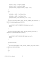
69
Chapter 4
dwGot |= 0x01; // set Dout_0 high
dwGot |= 0x02; // set Dout_1 high
printf("Set Dout_0 high, Set Dout_1 high ...\r\n");
}
else
{
dwGot &= ~0x01; // set Dout_0 low
dwGot &= ~0x02; // set Dout_1 low
printf("Set Dout_0 low, Set Dout_1 low ...\r\n");
}
if( !DeviceIoControl (hDev, ADV_IOCTL_WRITE_DO, &dwGot, 4,
NULL, 0, &dwNumReturned, NULL) )
{
printf("ADV_IOCTL_WRITE_DO failed! exit.\r\n");
break;
}
if( !DeviceIoControl (hDev, ADV_IOCTL_READ_DI, NULL, 0,
&dwGot, 4, &dwNumReturned, NULL) )
{
printf("ADV_IOCTL_READ_DI failed! exit.\r\n");
break;
}
if( dwGot & 0x01 )
{
DeviceIoControl(hDev, ADV_IOCTL_TURN_ON_LED1, NULL,
0, NULL, 0, NULL, NULL);
}
else
{
UNO-1019 User Manual
70
DeviceIoControl(hDev, ADV_IOCTL_TURN_OFF_LED1, NULL,
0, NULL, 0, NULL, NULL);
}
if( dwGot & 0x02 )
{
DeviceIoControl(hDev, ADV_IOCTL_TURN_ON_LED2, NULL,
0, NULL, 0, NULL, NULL);
}
else
{
DeviceIoControl(hDev, ADV_IOCTL_TURN_OFF_LED2, NULL,
0, NULL, 0, NULL, NULL);
}
Sleep(1000);
}
CloseHandle(hDev);
71
Chapter 4
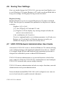
4.6 Saving Your Settings
Once you made changes for UNO-1019, you may need run RegSave.exe
to save Windows CE system Registry to CF card or on-board flash disk to
keep your settings. See Registry Saving section for detail.
Registry Saving
Running RegSave.exe to save system Registry to CF card or on-board
Flash. you can specify command line parameter for RegSave.exe shown
as below:
RegSave [-f] [-s] [-fs]
[-f] : Save Registry to Flash and CF card
[-s]: RegSave will not display any message despite whether the
action is succeeded or not.
[-fs]: combination of [-f] and [-s]
If you’re running RegSave.exe without parameter, it will only save
Registry to CF card and it will display message to notify you
whether the Registry has been successfully saved.
4.7 UNO-1019 Network Administration User Guide
Advantech’s UNO-1019 series is a built-in Windows CE solution offering
a pre-configured image with optimized onboard device drivers. WinCE
is a compact, high-efficient and hard real-time operating system that is
designed for embedded systems without HDD limitation.
UNO-1019 remote administration is a powerful function, which allow
users connect to filed-site UNO-1019 by standard browser and configure
UNO-1019’s network and system settings remotely.
UNO-1019 remote administration includes two major functions; network
administration and system administration.
Network administrationWith UNO-1019 well-configured, user can connect to local network or public network (Internet).
UNO-1019 User Manual
72
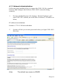
4.7.1 Network Administration
Following steps introduces how to connect the UNO-1019 by standard
browser, and configure the field-site UNO-1019’s network setting
remotely.
1.
Execute standard browser (for instance, Internet Explorer), and
enter UNO-1019 (which you would like to connect)’s IP address as
below,
IP address/networkadmin
Instance: 172.18.3.89/networkadmin
2.
Note:
System will ask you to enter password when you login UNO-1019
first time.
The default user name is ADMIN
73
Chapter 4
3.
Connect to the UNO-1019 again, and the system will ask you to
enter user name and password. After authorization, you will enter
Windows CE networking setup page.
UNO-1019 User Manual
74
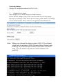
Network Settings
Change IP information about the UNO-1019.
1.
Change device name
Enter proper device name and press Submit button.
Please MUST change UNO-1019’s device name at your first usage.
But after you change UNO-1019's device name, please don't ever change
device name back to UNO-1019, it's not permitted for WinCE OS
Note: When you change the device name, UNO-1019 will need
some time to register to DNS (Domain Name Server) automatically. If you would like to search this UNO-1019 next
time, you can search it by device name instead of IP
address.
75
Chapter 4
Note:
You also could find device name in WinCE's "setting" /
"Control Panel" / "System" 's device name tag. You
could see below picture for referrence.
IPV6
If you want to enable “IPV6”, please check “Enable IPV6” and press
Submit button.
System will ask you to restart UNO-1019, the UNO-1019 will support
IPV6 after restarting.
UNO-1019 User Manual
76
Advanced Setting
“Advanced setting” allows ports to be statically reserved and mapped.
System will list all of the adapters present on the UNO-1019. You can
configure the adapter bindings as public, private, bridged, or default to
simply bind it to TCP/IP.
Caution:
Incorrect settings may render the UNO-1019 inoperable.
77
Chapter 4
User Accounts
“User Accounts” function allows you to add, modify and delete user
accounts on this UNO-1019. "ADMIN" is the only account allowed to
manage account information
Note:
The account we manage here is for network
service such as File server ,FTP,Telnet and
Web server, but NOT "ACCESS THIS ADMIN
WEBPAGE"
1.
Create a User Account
<1-A> Enter a user name in the “Create a new …” field, and press Create.
<1-B> Enter a password, and press Create Account button.
<1-C> System will create a user account according to your information.
If you would like to change the password of this user account, please
press Modify button behind the user name.
If you would like to delete the user account, please press Delete button
behind the user name.
UNO-1019 User Manual
78
2.
Create a Group
<2-A> Enter a group name in the “Create a new” field, and press Create.
<2-B> If you want to choose which users are members of group, please
press Modify button behind the group name.
Set the box next the user’s name to have them be part of this group.
79
Chapter 4
<2-C> If you want to delete a group, please press Delete button behind
the group name.
Features
Allows configuration of advanced gateway features. You can configure
the File server, FTP server, Telnet server and Web Server Administration
accordingly.
UNO-1019 User Manual
80
4.7.2 File Server
<A-1> Choose the folder in UNO-1019 you wish to share and then enter a
share name then press “Submit”.
<A-2> Press "Modify" to set up share permissions, choose the account
who will use file server function, then click "Allowed" then press
"Modify".
<A-3> You could use browser to access device name and test file server
function
81
Chapter 4
Note:
If you want to use password to protect UNO file server,
please key in your ADMIN password, chossing "PWD
Enabled" and click "Submit", every time you access file
server, UNO file sever will ask you a password of account
to enable file accessing.
UNO-1019 User Manual
82
Creating a Network Disk
Windows CE provides the command to enable remote network disk as a
local disk.
<Command>
Usage:
net use [<local name of folder on UNO-1019>|*] [<remote name>] [/
user:<username>] [/d]
or
net view <computername> | /DOMAIN:<domainname>
<Description>
[/d] Disable network disk
<Instance>
1.
Share the “temp folder” in the remote site (nb940902) to authorized
users, and set the permissions (read/write).
<EX> Remote Windows PC: <Computer name> = nb940902
<Shared folder name> = temp
<Authorized user name> = daniel.hsu
83
Chapter 4
2.
Execute the blow command by local UNO-1019’s command
prompt, and system will ask you to enter your user name, password
and domainif you would like to save your user name and password
as “default user”, please check “Update Default Credentials”.
<EX> net use UNO1019V1\\nb940902\temp /user:daniel.hsu
3.
The remote network disk (Ex:\\nb940902\temp) will launch in the
local UNO-1019’s “Network” folder.
UNO-1019 User Manual
84
If you want to delete this folder on UNO-1019 , you could execute the
command as below
<EX> net use UNO1019V1 \\nb940902\temp /user:daniel.hsu /d
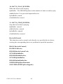
4.7.3 FTP Server
The FTP server accepts ftp connections and allows the UNO-1019 to be
configured remotely.
Basic Configuration
You can set following items in Basic Configuration field..
• Server Enabled- Will the FTP server accept incoming connections?
• Require Authentication- Will the FTP server prompt for user name and
password?
• Allow Anonymous Users- Allow users without an account on the server
to login to the server?
• Allow Anonymous Uploads- Allow anonymous users to upload and
change files?
• Allow Anonymous User to Virtual Roots- Allow anonymous users to
view and access files in virtual roots?
• Default Directory- The default directory that anonymous FTP users will
log in to.
85
Chapter 4
Logs
Use Logs section to control what information about the FTP transactions
is logged.
UNO-1019 User Manual
86
FTP Users
Use FTP Users section to control access to the FTP server for each user.
To add new user, please go to the “User Account” page.
You can configure a seprate home directory for each user by appending
the user’s name to home directory. Denying read permission to a user,
denies complete access to the FTP server for that user.
87
Chapter 4
Virtual Roots
You can add/delete virtual roots to the FTP server. Virtual roots allow you
map a physical directory to and directory with a different name.
UNO-1019 User Manual
88
4.7.4 Telnet Server
The telnet server accepts telnet connections and allows the UNO-1019 to
be configured remotely.
Telnet Server Configuration
• Server Enabled- Will the telnet server accept incoming connections?
• Require Authentication- Will the telnet server prompt for user name
and password?
Telnet Server Users
Choose which users can access the telnet server.
89
Chapter 4
4.7.5 Restart Network
Restart for network change to take effect. To make the changes you have
made take effect immediately, please press “Restart Networking” button,
and then the home gateway networking services will be restart.
UNO-1019 User Manual
90