1
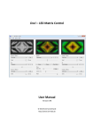
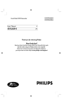
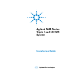
Agilent 1200 Infinity Series
Universal Interface Box
Agilent Technologies
Introduction
The Agilent 1200 Infinity Series Universal Interface Box (G1390B) is a
multipurpose accessory for the Agilent 1200 Infinity Series that extends
instrument communication capability to high quality analog and digital output
and input. It provides a general connection interface for existing and upcoming
Agilent sensors (e.g. pH-, temperature-, leak- sensors) and other accessory
equipment. Peak-based fraction collection with external detectors and
mass-based fraction collection with Agilent MS rely on the Universal Interface
Box II.
The Agilent 1200 Infinity Series Universal Interface Box (shortly referred to as
UIB II) replaces the Agilent 1100 Series Universal Interface Box (G1390A)
which is designed for peak-based fraction collection with external 3rd party
detectors via analog signal input or mass-based fraction collection with an
Agilent MS via digital signal trigger.
NOTE
The older G1390A is only needed for peak-triggering with legacy
Agilent 1100 Series LC-MSD (G1946 C/D) or Fraction Collector
Devices without RC.net drivers.
HiVijhA:9
;gdcih^YZ
>chigjbZciAVWZal^i]
HZg^VaCjbWZg
G^\]ih^YZ
GZVgh^YZ
AZ[ih^YZ
Figure 1
2
Overview of Universal Interface Box II (UIB II)
Features
Feature summary:
• Analog input for data collection from any type of 3rd-party detector such as
evaporative light scattering, laser-induced fluorescence, refractive index or
radioactivity detectors
• Analog-to-digital conversion of analog input for full data analysis through
Agilent chromatography data system, or for peak-based fraction collection
triggered by baseline threshold or peak slope (peak width > 0.2 seconds)
• Analog output to feed pump pressure traces or detector signals from Agilent
LC modules to third-party data systems
• General purpose input/output interface (GPIO/ERI) for digital mass-based
fraction triggering and general purpose use
• Low voltage output of 5 V and/or 24 V
• Four timetable programmable relay contacts for control of external devices
through close/open commands
• External leak sensor with separate input line for improved lab safety
• CAN connection to 1200 Series LC or 1200 Infinity Series LC modules
3
Deployment
The following sections describe some of the options for connecting a 1200
Infinity Series LC instrument with other modules or devices.
Additional Analog Out for every Agilent module to provide instrument or
chromatography signals to 3rd party receivers
(gYEVgin
HnhiZb
J>7>>
86CXdccZXi^dc
idhnhiZb
aZ[ih^YZ
G8#cZi89H
=EA8
A6Cid
89H
G^\]ih^YZ
6cVad\Dji7C8
Figure 2
Connection to provide additional analog out
NOTE
Use any of the following cable options depending on input device:
#061, #062, #064.
For explanations of the option numbers refer to Table 2 on page 14.
4
3rd party detector signal acquisition
(gYEVginYZiZXidg
6cVad\>c
XdccZXi^dc
J>7>>
G8#cZi89H
=EA8
86CXdccZXi^dc
idhnhiZb
aZ[ih^YZ
A6Cid
89H
G^\]ih^YZ
Figure 3
Connection to 3rd party device
NOTE
Use any of the following cable options depending on output device:
#063, #064.
For explanations of the option numbers refer to Table 2 on page 14.
5
3rd party (Peak Detection) triggered fraction collection
(gYEVgin9ZiZXidg
6cVad\>c
XdccZXi^dc
J>7>>
86CXdccZXi^dc
idhnhiZb
aZ[ih^YZ
G8#cZi89H
=EA8 ;8
A6Cid
89H
86CXdccZXi^dc
idhnhiZb
G^\]ih^YZ
Figure 4
Connection to 3rd party device for fraction triggering
NOTE
Use any of the following cable options depending on output device:
#063, #064.
For explanations of the option numbers refer to Table 2 on page 14.
6
Mass-Based fraction collection
BH
J>7>>
<E>DY^\^iVa
XdccZXi^dc
86CXdccZXi^dc
idhnhiZb
aZ[ih^YZ
G8#cZi89H
=EA8 ;8
A6CidDA
8]ZbHiVi^dc
86CXdccZXi^dc
idhnhiZb
G^\]ih^YZ
Figure 5
Connection for mass-based fraction collection
NOTE
Use following cable option for 61xx MS systems: #066.
For explanations of the option numbers refer to Table 2 on page 14.
7
External Contacts Board for time table programmable relay switching
allows control of peripheral equipment
Hl^iX]9Zk^XZh
J>7>>
86CXdccZXi^dc
idhnhiZb
aZ[ih^YZ
=EA8
G8#cZi89H
A6Cid
89H
G^\]ih^YZ
Id(gYEVgin
YZk^XZh
Figure 6
Connection to use external boards/relay switching functionality
NOTE
Use following cable option: #065.
For explanations of the option numbers refer to Table 2 on page 14.
8
Connectors of the UIB II
Overview of Connectors
:miZgcVaXdciVXih
:miZcYZYgZbdiZ
^ciZg[VXZ:G>
6cVad\>c
6cVad\Dji
Figure 7
Right side of the UIB II
86Cedgih
8dc[^\hl^iX]
:miZgcVaaZV`hZchdg
XdccZXidg
;jhZh
EdlZghl^iX]
EdlZgXdccZXidg
Figure 8
Left side of the UIB II
9
Typical Connection of UIB II to an Agilent LC Stack
6cVad\Djid[9ZiZXidg
H^\cVa6dg7
G^\]ih^YZ
6cVad\Djid[
9ZiZXidgdkZgJ>7>>
H^\cVa6dg7
86CXdccZXi^dcJ>7>>id6\^aZci>chigjbZciHiVX`
aZ[ih^YZd[i]ZJ>7>>
Figure 9
Connection UIB II to an Agilent LC stack (example)
Config Switch Settings of the UIB II
9^ehl^iX]&
9^ehl^iX]'
Figure 10
Table 1
Config Switch
Figure 11
Config Switch Settings
Dipswitch 1
Dipswitch 2
ON (1)
ON (1)
10
Function
ON (1)
OFF (0)
OFF (0)
OFF (0)
Dipswitch 1 and 2
Forced Cold Start
ON (1)
OFF (0)
Default/Standard Operation Mode
Resident Mode
Not Supported
Special Settings
Boot-Resident
Firmware update procedures may require this mode in case of firmware
loading errors (main firmware part). If you use the following switch settings
and power the instrument up again, the instrument firmware stays in the
resident mode. It is not operable as a module. It only uses basic functions of
the operating system for example, for communication. In this mode the main
firmware can be loaded (using update utilities).
Forced Cold Start
A forced cold start can be used to bring the module into a defined mode with
default parameter settings.
CAUTION
Loss of data
Forced cold start erases all methods and data stored in the
non-volatile memory. Exceptions are calibration settings,
diagnosis and repair log books which will not be erased.
➔ Save your methods and data before executing a forced cold
start.
Connector Descriptions
Analog Out / Analog In
H]^ZaY
6cVad\Dji
"
6cVad\Dji"
DjiejiKdaiV\Z/%#&"&K
Figure 12
Analog Out
Figure 13
Analog In
11
ERI / GPIO
-
&
.
&*
Figure 14
ERI / GPIO
Pin
Enh. Remote
1
IO 1
2
IO 2
3
IO 3
4
IO 4
5
IO 5
6
IO 6
7
IO 7
8
IO 8
9
1wire DATA
10
DGND
11
+5 V ERI out
12
PGND
13
PGND
14
+24 V ERI out
15
+24 V ERI out
ERI Interface (Enhanced Remote Interface) Description: This interface
contains 8 individual programmable input/output pins. In addition it provides
24 V power and 5 V power and a serial data line to detect and recognize further
add-ons that could be connected to this interface. This way the interface can
support various additional devices like sensors, triggers (in and out) and small
controllers, etc.
12
Relay / Aux.
*
&
&%
&*
Figure 15
PIN
+
&&
Relay / Aux.
Function
1
2
R1
3
4
R2
6
5
9
R3
8
7
10
R4
11
12
13
14
15
AUX 1
A-GND
AUX 2
A-GND
D-GND
13
Cables for UIB II
Cable Overview UIB II
Table 2
UIB II Cable Overview
Option
number
Cable part
number
#061
8120-8140
Description
Usage
For Analog Out
to BNC
BNC to BNC
#062
01046-60105
For Analog Out
BNC to general purpose
#063
35900-60910
For Analog
Input
C-Grid to general purpose
#064
G1390-60002
For Analog
Input/Out
BNC to C-Grid
14
Table 2
UIB II Cable Overview
Option
number
Cable part
number
#065
G1103-61611
Description
Usage
For External
Contacts
External contacts to general purpose
#066
G1968-60805
For
Mass-based
Fraction
Collection
ERI to MS RJ-45
#067
5188-8029
General
Purpose
(GPIO/ERI)
ERI to general purpose
15
Analog Cables
p/n 8120-1840
p/n G1390-60002
p/n 01046-60105
16
Contact/Lead
Signal Name
Shield
Analog -
Center
Analog +
Contact Lead
Signal Name
2
Analog -
3
Analog +
Shield
Analog -
Center
Analog +
Contact/Lead
Signal Name
Black
Analog -
Red
Analog +
Shield
Analog -
Center
Analog +
p/n G35900-60910
Contact/Lead
Signal Name
2
Analog -
3
Analog +
Black
Analog -
Red
Analog +
17
External Contact Cable
5
10
15
1
6
11
One end of this cable provides a 15-pin plug to be connected to
Agilent modules interface board. The other end is for general purpose.
Agilent Module Interface Board to general purposes
p/n G1103-61611
18
Color
Pin
Agilent
module
Signal Name
White
1
EXT 1
Brown
2
EXT 1
Green
3
EXT 2
Yellow
4
EXT 2
Grey
5
EXT 3
Pink
6
EXT 3
Blue
7
EXT 4
Red
8
EXT 4
Black
9
Not connected
Violet
10
Not connected
Grey/pink
11
Not connected
Red/blue
12
Not connected
White/gr
een
13
Not connected
Brown/gr
een
14
Not connected
White/yel
low
15
Not connected
General Purpose Cable
Table 3
GPIO General Purpose Cable (5188-8029) descriptions
Wire Color
PIN
Enh. Remote
Green
1
IO 1
Violet
2
IO 2
Blue
3
IO 3
Yellow
4
IO 4
Black
5
IO 5
Orange
6
IO 6
Red
7
IO 7
Brown
8
IO 8
Gray
9
1 wire DATA
NC
10
DGND
NC
11
+5 V ERI out
NC
12
PGND
NC
13
PGND
NC
14
+24 V ERI out
White
15
+24 V ERI out
19
Representation in the Driver Software
The representation of the UIB II in the dashboard of the Rapid Control LC
Driver provides information on the following items:
• Connectors
• Analog In
• Analog Out
• Relay contacts
• Voltage out information (if used)
Figure 16
Table 4
Item
Dashboard tile of the G1390B driver
Function of items in UIB II graphic
Function
Shows the source of the Analog Out signal (upper) or Test Signal
(lower)
Shows the current states of the four external contacts
Shows which Voltage Out voltages are currently enabled.
20
Appendix
Electrical Connections
• The CAN bus is a serial bus with high speed data transfer. The two
connectors for the CAN bus are used for internal module data transfer and
synchronization.
• The power input socket accepts a line voltage of 100 – 240 VAC ±10 % with a
line frequency of 50 or 60 Hz. Maximum power consumption varies by
module. There is no voltage selector on your module because the power
supply has wide-ranging capability. There are no externally accessible fuses,
because automatic electronic fuses are implemented in the power supply.
NOTE
Never use cables other than the ones supplied by Agilent
Technologies to ensure proper functionality and compliance with
safety or EMC regulations.
Serial Number Information 1200 Series and 1290 Infinity
The serial number information on the instrument labels provide the following
information:
Format
CCIIISSSSS
CC
CC country of manufacturing
• DE = Germany
• JP = Japan
• CN = China
III
identifier: normally only changed at significant
modifications
SSSSS
real serial number
21
Physical Specifications
Table 5
Physical Specifications
Type
Specification
Weight
0.9 kg (2 lbs)
Dimensions
(height × width × depth)
165 x 135 x 55 mm (6.5 x 5.3 x 2.2 inches)
Line voltage
100 – 240 VAC, ± 10 %
Line frequency
50 or 60 Hz, ± 5 %
Power consumption
140 VA / 65 W
Ambient operating
temperature
4–55 °C (39–131 °F)
Ambient non-operating
temperature
-40 – 70 °C (-40 – 158 °F)
Humidity
< 95 % r.h. at 40 °C (104 °F)
Operating altitude
Up to 2000 m (6562 ft)
Non-operating altitude
Up to 4600 m (15091 ft)
For storing the module
Safety standards:
IEC, CSA, UL
Installation category II, Pollution degree 2
For indoor use only.
22
Comments
Wide-ranging capability
Maximum
Non-condensing
Technical and Performance Specifications
Table 6
Performance specifications
Type
Comment
High breaking capacity fuse
2.0 A, 250 V
Signal specifications:
CAN
2-wire serial bus system
Analog-input
Input Range= -1 V to 1 V
Resolution = 24 bit A/D-Converter
Effective System Resolution = +/- 1 uV (rms)
GPIO
TTL compatible Input and Output
Open collector characteristic Input voltage range 0 V to 5 V
Relay outputs
2 contact closure outputs and 2 double throw outputs
Imax = 250 mA
Umax = 30 V DC/AC
The contacts are protected by a self-resetting PTC-fuse
23
Delivery Checklist
Ensure all parts and materials have been delivered with your module. The
delivery checklist is shown below. Please report any missing or damaged parts
to your local Agilent Technologies sales and service office.
p/n
Description
G1390-90010
1200 Infinity Series UIB-II User Manual EN
G4800-64500
Agilent 1200 Infinity Series User Documentation DVD
5181-1519
CAN cable, Agilent module to module, 1 m
Power cord
Damaged Packaging
If the delivery packaging shows signs of external damage, please call your
Agilent Technologies sales and service office immediately. Inform your service
representative that the instrument may have been damaged during shipment.
CAUTION
"Defective on arrival" problems
If there are signs of damage, please do not attempt to install the
module. Inspection by Agilent is required to evaluate if the
instrument is in good condition or damaged.
➔ Notify your Agilent sales and service office about the damage.
➔ An Agilent service representative will inspect the instrument at
your site and initiate appropriate actions.
24
Condensation
CAUTION
Condensation within the module
Condensation will damage the system electronics.
➔ Do not store, ship or use your module under conditions where
temperature fluctuations could cause condensation within the
module.
➔ If your module was shipped in cold weather, leave it in its box
and allow it to warm slowly to room temperature to avoid
condensation.
Bench Space
The module dimensions and weight (see Table 5 on page 22) allow you to place
the module on almost any desk or laboratory bench. It needs an additional
2.5 cm (1.0 inches) of space on either side and approximately 8 cm (3.1 inches)
at the left side for air circulation and electric connections.
If the bench shall carry a complete HPLC system, make sure that the bench is
designed to bear the weight of all modules.
Do not cover ventilation slots of the module.
25
Power Cords
Different power cords are offered as options with the module. The female end
of all power cords is identical. It plugs into the power-input socket at the left
side. The male end of each power cord is different and designed to match the
wall socket of a particular country or region.
WA R N I N G
Absence of ground connection or use of unspecified power cord
The absence of ground connection or the use of unspecified
power cord can lead to electric shock or short circuit.
➔ Never operate your instrumentation from a power outlet that
has no ground connection.
➔ Never use a power cord other than the Agilent Technologies
power cord designed for your region.
WA R N I N G
Use of unsupplied cables
Using cables not supplied by Agilent Technologies can lead to
damage of the electronic components or personal injury.
➔ Never use cables other than the ones supplied by Agilent
Technologies to ensure proper functionality and compliance
with safety or EMC regulations.
WA R N I N G
Unintended use of supplied power cords
Using power cords for unintended purposes can lead to personal
injury or damage of electronic equipment.
➔ Never use the power cords that Agilent Technologies supplies
with this instrument for any other equipment.
26
Power Considerations
The module power supply has wide ranging capability. It accepts any line
voltage in the range described in Table 5 on page 22. Consequently there is no
voltage selector at the left side of the module. There are also no externally
accessible fuses, because automatic electronic fuses are implemented in the
power supply.
WA R N I N G
Hazard of electrical shock or damage of your instrumentation
can result, if the devices are connected to a line voltage higher
than specified.
➔ Connect your instrument to the specified line voltage only.
WA R N I N G
The module is partially energized when switched off, as long as
the power cord is plugged in.
Repair work at the module can lead to personal injuries, e.g.
electrical shock, when the cover is opened and the module is
connected to power.
➔ Always unplug the power cable before opening the cover.
➔ Do not connect the power cable to the instrument while the
covers are removed.
CAUTION
Inaccessible power plug.
In case of emergency it must be possible to disconnect the
instrument from the power line at any time.
➔ Make sure the power connector of the instrument can be easily
reached and unplugged.
➔ Provide sufficient space behind the power socket of the
instrument to unplug the cable.
27
The Waste Electrical and Electronic Equipment Directive
Abstract
The Waste Electrical and Electronic Equipment (WEEE) Directive
(2002/96/EC), adopted by EU Commission on 13 February 2003, is introducing
producer responsibility on all electric and electronic appliances starting with
13 August 2005.
NOTE
This product complies with the WEEE Directive (2002/96/EC)
marking requirements. The affixed label indicates that you must not
discard this electrical/electronic product in domestic household
waste.
Product Category:
With reference to the equipment types in the WEEE Directive Annex I,
this product is classed as a Monitoring and Control Instrumentation
product.
NOTE
Do not dispose off in domestic household waste
To return unwanted products, contact your local Agilent office, or see
www.agilent.com for more information.
28
Safety Symbols
Table 7
Safety Symbols
Symbol
Description
The apparatus is marked with this symbol when the user
should refer to the instruction manual in order to protect
risk of harm to the operator and to protect the apparatus
against damage.
Indicates dangerous voltages.
Indicates a protected ground terminal.
Indicates eye damage may result from directly viewing
the light produced by the deuterium lamp used in this
product.
The apparatus is marked with this symbol when hot
surfaces are available and the user should not touch it
when heated up.
WA R N I N G
A WARNING
alerts you to situations that could cause physical injury or
death.
➔ Do not proceed beyond a warning until you have fully
understood and met the indicated conditions.
CAUTION
A CAUTION
alerts you to situations that could cause loss of data, or damage of
equipment.
➔ Do not proceed beyond a caution until you have fully
understood and met the indicated conditions.
29
Operation
Before applying power, comply with the installation section. Additionally the
following must be observed.
Do not remove instrument covers when operating. Before the instrument is
switched on, all protective earth terminals, extension cords,
auto-transformers, and devices connected to it must be connected to a
protective earth via a ground socket. Any interruption of the protective earth
grounding will cause a potential shock hazard that could result in serious
personal injury. Whenever it is likely that the protection has been impaired,
the instrument must be made inoperative and be secured against any intended
operation.
Make sure that only fuses with the required rated current and of the specified
type (normal blow, time delay, and so on) are used for replacement. The use of
repaired fuses and the short-circuiting of fuse holders must be avoided.
Some adjustments described in the manual, are made with power supplied to
the instrument, and protective covers removed. Energy available at many
points may, if contacted, result in personal injury.
Any adjustment, maintenance, and repair of the opened instrument under
voltage should be avoided whenever possible. When inevitable, this has to be
carried out by a skilled person who is aware of the hazard involved. Do not
attempt internal service or adjustment unless another person, capable of
rendering first aid and resuscitation, is present. Do not replace components
with power cable connected.
Do not operate the instrument in the presence of flammable gases or fumes.
Operation of any electrical instrument in such an environment constitutes a
definite safety hazard.
Do not install substitute parts or make any unauthorized modification to the
instrument.
Capacitors inside the instrument may still be charged, even though the
instrument has been disconnected from its source of supply. Dangerous
voltages, capable of causing serious personal injury, are present in this
instrument. Use extreme caution when handling, testing and adjusting.
30
When working with solvents, observe appropriate safety procedures (for
example, goggles, safety gloves and protective clothing) as described in the
material handling and safety data sheet by the solvent vendor, especially when
toxic or hazardous solvents are used.
Safety Standards
This is a Safety Class I instrument (provided with terminal for protective
earthing) and has been manufactured and tested according to international
safety standards.
General Safety Information
The following general safety precautions must be observed during all phases of
operation, service, and repair of this instrument. Failure to comply with these
precautions or with specific warnings elsewhere in this manual violates safety
standards of design, manufacture, and intended use of the instrument. Agilent
Technologies assumes no liability for the customer’s failure to comply with
these requirements.
WA R N I N G
Ensure the proper usage of the equipment.
The protection provided by the equipment may be impaired.
➔ The operator of this instrument is advised to use the
equipment in a manner as specified in this manual.
Agilent Technologies on Internet
For the latest information on products and services visit our worldwide web
site on the Internet at:
http://www.agilent.com
31
*G1390-90011*
*G1390-90011*
G1390-90011
Part Number:
G1390-90011
Edition: 02/2013
Printed in Germany
© Agilent Technologies, Inc 2012,
2013
Agilent Technologies, Inc
Hewlett-Packard-Strasse 8
76337 Waldbronn, Germany