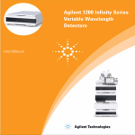
Download G1364-90010 - Agilent Technologies
Transcript
Agilent 1200 Series Analytical and Preparative Scale Fraction Collectors User Manual A Notices © Agilent Technologies, Inc. 2006 Warranty No part of this manual may be reproduced in any form or by any means (including electronic storage and retrieval or translation into a foreign language) without prior agreement and written consent from Agilent Technologies, Inc. as governed by United States and international copyright laws. The material contained in this document is provided “as is,” and is subject to being changed, without notice, in future editions. Further, to the maximum extent permitted by applicable law, Agilent disclaims all warranties, either express or implied, with regard to this manual and any information contained herein, including but not limited to the implied warranties of merchantability and fitness for a particular purpose. Agilent shall not be liable for errors or for incidental or consequential damages in connection with the furnishing, use, or performance of this document or of any information contained herein. Should Agilent and the user have a separate written agreement with warranty terms covering the material in this document that conflict with these terms, the warranty terms in the separate agreement shall control. Microsoft ® is a U.S. registered trademark of Microsoft Corporation. Manual Part Number G1364-90010 Edition 02/06 Printed in Germany Agilent Technologies Hewlett-Packard-Strasse 8 76337 Waldbronn receive no greater than Restricted Rights as defined in FAR 52.227-19(c)(1-2) (June 1987). U.S. Government users will receive no greater than Limited Rights as defined in FAR 52.227-14 (June 1987) or DFAR 252.227-7015 (b)(2) (November 1995), as applicable in any technical data. Safety Notices CAUTION A CAUTION notice denotes a hazard. It calls attention to an operating procedure, practice, or the like that, if not correctly performed or adhered to, could result in damage to the product or loss of important data. Do not proceed beyond a CAUTION notice until the indicated conditions are fully understood and met. Technology Licenses The hardware and/or software described in this document are furnished under a license and may be used or copied only in accordance with the terms of such license. Restricted Rights Legend If software is for use in the performance of a U.S. Government prime contract or subcontract, Software is delivered and licensed as “Commercial computer software” as defined in DFAR 252.227-7014 (June 1995), or as a “commercial item” as defined in FAR 2.101(a) or as “Restricted computer software” as defined in FAR 52.227-19 (June 1987) or any equivalent agency regulation or contract clause. Use, duplication or disclosure of Software is subject to Agilent Technologies’ standard commercial license terms, and non-DOD Departments and Agencies of the U.S. Government will Agilent 1200 Series Fraction Collectors User Manual WA R N I N G A WARNING notice denotes a hazard. It calls attention to an operating procedure, practice, or the like that, if not correctly performed or adhered to, could result in personal injury or death. Do not proceed beyond a WARNING notice until the indicated conditions are fully understood and met. In This Guide… This manual contains technical reference information about the Agilent 1200 Series fraction collectors analytical and preparative scale. The manual describes the following: 1 Installing the Fraction Collector This chapter provides information about the installation of the Agilent 1200 Series fraction collectors AS and PS. 2 Configuration and Operation of the Fraction Collector This chapter describes the configuration and operation of the fraction collector including guidelines to optimize the system and to avoid problems. 3 Control Module Screens of the Fraction Collector The reference to the screens of the Agilent 1200 Series control module is provided in the chapter. 4 Troubleshooting and Test Functions This chapter describes the modules built-in troubleshooting and test functions. 5 Repairing the Fraction Collector This chapter contains instructions on simple repair and maintenance procedures. 6 Parts and Materials This chapter contains lists for identification of common repair and maintenance parts. 7 Specifications This chapter contains performance specifications of the fraction collectors. A Safety Information This appendix provides a safety summary. Agilent 1200 Series Fraction Collectors User Manual 3 4 Agilent 1200 Series Fraction Collectors User Manual Contents 1 Installing the Fraction Collector Site Requirements 12 Power Consideration Power Cords 13 Bench Space 13 Environment 14 11 12 Unpacking the Fraction Collector Damaged Packaging 16 Delivery Checklist 16 Accessory Kits 17 16 Optimizing the Stack Configuration Installing the Fraction Collector 20 25 Installing a Thermostatted Fraction Collector Flow Connections to the Fraction Collector 29 34 Fraction Collector Trays 37 Installing the Fraction Collector Trays 37 Numbering of Vial, Test Tube and Well-plate Positions Configure Well-plate Types 40 Transporting the Fraction Collector 2 38 43 Configuration and Operation of the Fraction Collector 45 Configuration of the Fraction Collector 46 Configuration of the fraction collector in the ChemStation Configuring multiple fraction collectors 50 Agilent 1200 Series Fraction Collectors User Manual 46 5 Contents Delay volumes and delay calibration 52 Delay times and volumes 52 Detector signal delay 53 Performing a delay calibration with an UV detector Performing a delay calibration with an MSD 61 Making Your Own Calibration Method 66 Setting up a Fraction Collector Method Fraction Trigger Mode 68 Fraction Preview 72 57 67 Starting your run with fraction collection 74 Assignment of Start Location for fraction collection Online tick marks 77 74 Viewing your Results 78 Data Analysis 78 Report 79 Special Applications 80 Pooling 80 Sample Recovery 81 Semi-preparative operation 82 Using high test tubes in the analytical scale fraction collector Optimizing fraction collection 84 Limitations and how to avoid problems 85 Check-out Procedures 86 Check-out procedure for UV-triggered fraction collection AS Check-out procedure for UV-triggered fraction collection PS Application Notes 3 86 89 91 Control Module Screens of the Fraction Collector Major keys on the Agilent 1200 Series control module 6 83 93 94 Agilent 1200 Series Fraction Collectors User Manual Contents 4 Screens available from the Analysis view 95 Screens available from the System view 109 Troubleshooting and Test Functions 127 Status Indicators 128 Error Messages 128 Maintenance Functions 128 Transport Unit Self Alignment 128 Status Indicators 129 Power Supply Indicator 129 Instrument Status Indicator 130 Maintenance Functions 131 Transport Unit Self Alignment 133 Step Commands 135 Troubleshooting 136 5 Repairing the Fraction Collector 137 Introduction into Repairing the Fraction Collector Simple Repairs 138 Cleaning the Fraction Collector 138 Overview of Main Repair Procedures 138 139 Simple Repairs 140 Replacing the Inlet/Waste Tubings 141 Replacing the Valve to Needle Tubing 145 Exchanging the Preparative Needle Assembly 148 Exchanging the Analytical Needle Assembly 150 Exchanging the Diverter Valve 153 Exchanging the Internal Tray 156 Agilent 1200 Series Fraction Collectors User Manual 7 Contents 6 Parts and Materials 161 Supported Trays for Fraction Collectors List of Recommended Test Tubes 162 164 List of Recommended Vials and Caps 165 List of Recommended Plates and Closing Mats 168 Transport Unit Assembly (Preparative Scale) 170 Transport Unit Assembly (Analytical Scale) 171 Needle Assemblies 173 Diverter-Valve Assembly Tubing Kits 174 175 Internal Tray Assembly 176 Fraction Collector Accessory Kit 7 Specifications 177 179 Performance Specifications for the Fraction Collectors A Safety Information 180 187 Safety Information 188 General 188 Operation 189 Safety Symbols 190 Lithium Batteries Information Radio Interference 192 Test and Measurement 191 192 Sound Emission 193 Manufacturer’s Declaration 8 193 Agilent 1200 Series Fraction Collectors User Manual Contents Solvent Information Solvents 194 194 Agilent Technologies on Internet Index 195 197 Agilent 1200 Series Fraction Collectors User Manual 9 Contents 10 Agilent 1200 Series Fraction Collectors User Manual Agilent 1200 Series Fraction Collectors User Manual 1 Installing the Fraction Collector Site Requirements 12 Unpacking the Fraction Collector 16 Optimizing the Stack Configuration 20 Installing the Fraction Collector 25 Installing a Thermostatted Fraction Collector 29 Flow Connections to the Fraction Collector 34 Fraction Collector Trays 37 Configure Well-plate Types 40 Transporting the Fraction Collector 43 Agilent Technologies 11 1 Installing the Fraction Collector Site Requirements Site Requirements A suitable site environment is important to ensure optimum performance of the fraction collector. Power Consideration The fraction collector power supply has wide-ranging capability (see Table 1 on page 14). Consequently there is no voltage selector in the rear of the fraction collector. There are also no externally accessible fuses, as automatic electronic fuses are integrated in the power supply. The thermostatted fraction collector comprises two modules, the fraction collector (G1364B or G1364C) and the thermostat (G1330A). Both modules have a separate power supply and a power plug for the line connections. The two modules are connected by a control cable and both are turned on by the fraction collector module. The thermostat power supply has two externally accessible fuses. 12 WA R N I N G To disconnect the fraction collector from line power, unplug the power cord. The power supply still uses some power, even if the power switch on the front panel is turned off. WA R N I N G To disconnect the thermostatted fraction collector from line power, unplug the power cord from the fraction collector and the thermostat. The power supplies still use some power, even if the power switch on the front panel is turned off. Please make sure that it is always possible to access the power plug. WA R N I N G Shock hazard or damage of your instrumentation can result if the devices are connected to a line voltage higher than specified. Agilent 1200 Series Fraction Collectors User Manual Installing the Fraction Collector Site Requirements 1 Power Cords Your fraction collector is delivered with a power cord which matches the wall socket of your particular country or region. The plug on the power cord which connects to the rear of the instrument is identical for all types of power cord. WA R N I N G Never operate your instrumentation from a power outlet that has no ground connection. Never use a power cord other than the power cord designed for your region. WA R N I N G Never use cables other than the ones supplied by Agilent Technologies to ensure proper functionality and compliance with safety or EMC regulations. Bench Space The fraction collector dimensions and weight (see Table 1 on page 14) allow the instrument to be placed on almost any laboratory bench. The instrument requires an additional 2.5 cm (1.0 inch) of space on either side, and approximately 8 cm (3.1 inches) at the rear for the circulation of air, and room for electrical connections. Ensure the fraction collector is installed in a horizontal position. The thermostatted fraction collector dimensions and weight (see Table 2 on page 15) allow the instrument to be placed on almost any laboratory bench. The instrument requires an additional 25 cm (10 inches) of space on either side for the circulation of air, and approximately 8 cm (3.1 inches) at the rear for electrical connections. Ensure the fraction collector is installed in a horizontal position. If a complete Agilent 1200 Series LC system is to be installed on the bench, make sure that the bench is designed to carry the weight of all the modules. For a complete system including the thermostatted fraction collector it is recommended to position the modules in two stacks, see “Recommended Stack Configuration - Fraction Collector in an Analytical System (Front View)” on page 21. Make sure that in this configuration there is 25 cm (10 inches) space on either side of the thermostatted fraction collector for the circulation of air. Agilent 1200 Series Fraction Collectors User Manual 13 1 Installing the Fraction Collector Site Requirements Environment Your fraction collector will work within specifications at ambient temperatures and relative humidity as described in Table 1 and Table 2 on page 15. CAUTION Table 1 Do not store, ship or use your fraction collector under conditions where temperature fluctuations may cause condensation within the fraction collector. Condensation will damage the system electronics. If your fraction collector was shipped in cold weather, leave it in its box, and allow it to warm up slowly to room temperature to avoid condensation. Physical Specifications - Fraction Collectors (G1364B, G1364C) Type Specification Weight 13.5 kg (29.8 lbs) Dimensions (height × width × depth) 200 × 345 × 440 mm (8 × 13.5 × 17 inches) Line voltage 100 – 240 VAC, ±10 % Line frequency 50 or 60 Hz, ±5 % Power consumption (apparent power) 200 VA Maximum Power consumption (active power) 180 W Maximum Ambient operating temperature 4 – 55 °C (41 – 131 °F) Ambient non-operating temperature -40 – 70 °C (-4 – 158 °F) Humidity < 95 %, at 25 – 40 °C (77 – 104 °F) Operating Altitude Up to 2000 m (6500 ft) Non-operating altitude Up to 4600 m (14950 ft) Safety standards: IEC, CSA, UL Installation Category II, Pollution Degree 2. For indoor use only. 14 Comments Wide-ranging capability Non-condensing For storing the fraction collector Agilent 1200 Series Fraction Collectors User Manual Installing the Fraction Collector Site Requirements Table 2 1 Physical Specifications - Thermostat (G1330B) Type Specification Weight 18.5 kg (40.7 lbs) Dimensions (height × width × depth) 140 × 345 × 435 mm (5.5 × 13.5 × 17 inches) Line voltage 100 – 120 or 220 – 240 VAC, ± 10 % Line frequency 50 or 60 Hz, ± 5 % Power consumption (active power) 210 W Maximum Power consumption (apparent power) 260 VA Maximum Ambient operating temperature 4 – 40 °C (41 – 131 °F) Ambient non-operating temperature -40 – 70 °C (-4 – 158 °F) Humidity < 95 %, at 25 – 40 °C (77 – 104 °F) Operating Altitude Up to 2000 m (6500 ft) Non-operating altitude Up to 4600 m (14950 ft) Safety standards: IEC, CSA, UL, EN Installation Category II, Pollution Degree 2. For indoor use only. Agilent 1200 Series Fraction Collectors User Manual Comments Wide-ranging capability Non-condensing For storing the fraction collector 15 1 Installing the Fraction Collector Unpacking the Fraction Collector Unpacking the Fraction Collector CAUTION If you need to ship the fraction collector at a later date, always use the shipping protection foam parts (see “Transporting the Fraction Collector” on page 43). Damaged Packaging Upon receipt of your fraction collector, inspect the shipping containers for any signs of damage. If the containers or cushioning material are damaged, keep them until the contents have been checked for completeness and the fraction collector has been mechanically and electrically checked. If the shipping container or cushioning material is damaged, notify the carrier and keep the shipping material for the carrier‘s inspection. CAUTION If there are signs of damage to the fraction collector, please do not attempt to install the fraction collector. Delivery Checklist Ensure all parts and materials have been delivered with the fraction collector. For this compare the shipment content with the checklist included in each instrument box. Please report missing or damaged parts to your local Agilent Technologies sales and service office. Three models of Agilent 1200 Series fraction collector are available: • G1364B Fraction Collector, preparative scale, designed for flow rates up to 100 ml / min. and for the use with vials, deep well plates and test tubes up to 100 mm height. • G1364C Fraction Collector, analytical scale, designed for flow rates below 10 ml / min. (can be modified for higher flow rates) and for the use with vials, test tubes of up to 75 mm height, well-plates and a 40-funnel tray connecting to external locations of any size 16 Agilent 1200 Series Fraction Collectors User Manual Installing the Fraction Collector Unpacking the Fraction Collector 1 • G1364C Thermostatted Fraction Collector, analytical scale, can be created by additionally ordering and installing a G1330B Fraction Collector Thermostat. The terms (thermostatted) analytical scale fraction collector and the preparative scale fraction collector refer to these Agilent 1200 Series modules in this manual. Unless otherwise stated all information in this section is valid for all models. Table 3 Delivery Checklist for the G1364B (preparative scale) and G1364C (analytical scale) Fraction Collector Description Quantity Fraction collector module with inlet / waste tubing assembly 1 Power cord, local (Matching the sockets in your country or region) 1 Accessory kit (see below) 1 Delay Calibrant G1946-85020 1 Table 4 Delivery Checklist for the G1330B Thermostat Module (optional) Description Quantity Thermostat Module 1 Power cord, local (Matching the sockets in your country or region) 1 Accessory kit thermostat module (see below) 1 Accessory Kits Each shipment contents an Accessory kit with the necessary tools to install the system and to have an operating system. Agilent 1200 Series Fraction Collectors User Manual 17 1 Installing the Fraction Collector Unpacking the Fraction Collector Table 5 Fraction Collector Accessory Kit Contents G1364-68725 Description Quantity Part Number Wrench, open end, 4mm 1 8710-1534 Wrench, open end, 1/4-5/16 inch 1 8710-0510 Hex key 2.0 mm 1 8710-2476 Finger tight fittings, 1/16” f-120* 3 0100-1516 Waste tubing (1.2 m)† 1 5062-2463 Y-Type Fitting for waste tubing‡ 1 5065-9971 CAN cable, 1 m 1 5181-1519 Air channel adapter 1 G1329-43200 Sticking clamp for corrugated waste tubing (large)** 3 5065-9976 Sticking clamp for waste tubing (small)†† 3 5065-9976 ESD wrist strap 1 9300-1408 Tray for 15 x 6 ml vials 1 G1313-44513 Tray for 40 x 2 ml vials 1 G1313-44512 * Reorder gives pack of 2 † Reorder gives 5 m ‡ Reorder gives pack of 10 ** Reorder gives 10 clamps for corrugated waste tubing (large)) †† Reorder gives 10 clamps for waste tubing (small) • The Accessory kit (G1330-68705) shown in Table 6 is shipped with the (G1330B) thermostat module if the thermostat module was ordered. Table 6 (Optional) Thermostat Module Accessory Kit Contents G1330-68705 Description Waste tubing (1.2 m) * Cable thermostat module to fraction collector 18 Quantity Part Number 1 5062-2463 1 G1330-81600 Agilent 1200 Series Fraction Collectors User Manual Installing the Fraction Collector Unpacking the Fraction Collector 1 * Reorder gives 5 m Agilent 1200 Series Fraction Collectors User Manual 19 1 Installing the Fraction Collector Optimizing the Stack Configuration Optimizing the Stack Configuration If your fraction collector is part of a system, you can ensure optimum performance and minimum delay volume by installing the following configuration. • Figure 1 and Figure 2 on page 22 show the configuration recommended for the fraction collector in an analytical scale system. • Figure 3 on page 23 and Figure 4 on page 24 show the configuration recommended for the fraction collector with a preparative scale system. NOTE 20 Agilent 1200 Series LC purification systems can comprise many different LC modules. This section describes some common stack configurations and general considerations. On more complex systems, e.g. with two or more fraction collectors or with mass selective detector, other stack configurations might show advantages. Agilent 1200 Series Fraction Collectors User Manual Installing the Fraction Collector Optimizing the Stack Configuration 1 Solvent Compartment Degasser Pump UV-Vis Detector Autosampler Fraction Collector Column Compartment Figure 1 NOTE Recommended Stack Configuration - Fraction Collector in an Analytical System (Front View) For information about connecting an Agilent LC-MSD, a Non-1200 or Non-UV-Vis detector to the system, please refer to the “User’s Guide for Purification / High Throughput System”, PN G2262-90010 or to the “Installation Note for the Mass Based Fraction Collection Kit”. Agilent 1200 Series Fraction Collectors User Manual 21 1 Installing the Fraction Collector Optimizing the Stack Configuration Solvent Compartment Degasser GPIB or LAN to LC ChemStation UV-Vis Detector Pump Autosampler CAN Bus cable Fraction Collector Column Compartment Figure 2 22 Recommended Stack Configuration - Fraction Collector in an Analytical System (Rear View) NOTE If a G1330B ALS thermostat is part of the system it must always be installed underneath the thermostatted injector or fraction collector (see “Installing a Thermostatted Fraction Collector” on page 29). NOTE The fraction collector should never be positioned on top of a module that generates heat. This could lead to an unwanted evaporation of fractions in the fraction collector (e.g. Agilent 1200 Series thermostatted column compartment G1316A/B or Agilent 1200 Series diode-array detectors G1315B/C. Agilent 1200 Series Fraction Collectors User Manual Installing the Fraction Collector Optimizing the Stack Configuration 1 Solvent Compartment Preparative Pump A Column Organizer Preparative Pump B UV-Vis Detector Autosampler Fraction Collector Figure 3 NOTE Recommended Stack Configuration - Fraction Collector in a Preparative System (Front View) For information about connecting an Agilent LC-MSD, a Non-1200 or Non-UV-Vis detector to the system, please refer to the “User’s Guide for Purification / High Throughput System”, PN G2262-90010 or to the “Installation Note for the Mass Based Fraction Collection Kit”. Agilent 1200 Series Fraction Collectors User Manual 23 1 Installing the Fraction Collector Optimizing the Stack Configuration Solvent Compartment Preparative Pump A Column Organizer GPIB or LAN to ChemStation Preparative Pump B CAN Bus Cable UV-Vis Detector Autosampler Fraction Collector Figure 4 24 Recommended Stack Configuration - Fraction Collector in a Preparative System (Rear View) NOTE If a G1330B ALS thermostat is part of the system it must always be installed underneath the module, that is thermostatted injector or fraction collector (see “Installing a Thermostatted Fraction Collector” on page 29). NOTE The fraction collector should never be positioned on top of a module that generates heat, which can lead to an unwanted evaporation of fractions in the fraction collector (e.g. Agilent 1200 Series thermostatted column compartment G1316A/B or Agilent 1200 Series diode-array detectors G1315B/C. Agilent 1200 Series Fraction Collectors User Manual Installing the Fraction Collector Installing the Fraction Collector 1 Installing the Fraction Collector Preparation Locate bench space Provide power connections Unpack the fraction collector Parts required Fraction Collector Power cord, Chemstation and/or Control Module G1323B WA R N I N G When opening capillary or tube fittings solvents may leak out. Please observe appropriate safety procedures (for example, goggles, safety gloves and protective clothing) as described in the material handling and safety data sheet supplied by the solvent vendor, especially when toxic or hazardous solvents are used. WA R N I N G To avoid personal injury, keep fingers away from the needle area during fraction collector operation. Do not attempt to insert or remove a vial or a plate when the needle is positioned. 1 Install the LAN interface board in the fraction collector (if required). 2 Remove the adhesive tape which covers the side and front doors. 3 Open the front door and remove the left side door. 4 Remove the transport protection foam. 5 Install the corrugated waste tube in the plastic port at the front bottom center of the instrument. Slide the waste tubing coming from the internal tray (if present) through the plastic port and the corrugated waste tube (see Figure 5 on page 26). Route the corrugated waste tubing into a waste container. Agilent 1200 Series Fraction Collectors User Manual 25 1 Installing the Fraction Collector Installing the Fraction Collector 2 1 Figure 5 Installing the Corrugated Waste Tubing in the Plastic Port 6 Re-install the left side door (take care of the magnet at the back). Ensure the side door is correctly installed (its presence is sensed by a hall sensor, a missing side door will result in a NOT-READY state of the instrument). 7 Place the fraction collector in the stack or on the bench in all horizontal position. 8 Ensure the power switch at the front of the fraction collector is OFF. 9 Connect the power cable to the power connector at the rear of the fraction collector. 10 Connect the CAN cable to the other Agilent 1200 Series LC modules. 11 If an Agilent ChemStation is the controller, it must be connect to the LAN interface (should be installed to the detector). 12 Connect the APG remote cable (optional) for non Agilent 1200 Series instruments. 13 Install the tray that has been delivered for your fraction collector. The test tube trays can be adjusted in height, depending on the height of the used test tubes. To adjust the height of the trays, press against the snappers at 26 Agilent 1200 Series Fraction Collectors User Manual Installing the Fraction Collector Installing the Fraction Collector 1 the guides in the 4 corners of a tray and move the top plate of the tray up or down (see Figure 6 on page 27). NOTE The preparative scale fraction collector (G1364B) and the analytical scale fraction collector (G1364C) are shipped with two trays (40x2 ml half tray and 15 x 6ml half tray). Figure 6 Adjusting the Height of the (Full) Test Tube Trays. 14 Turn ON power by pushing the button at the lower left hand side of the fraction collector. 15 The exhaust fan will turn ON and remove potential solvent vapor from the inside of the instrument. After 2 minutes close the front door. Then the fraction collector will start the hardware initialization process. At the end of this process the status LED should be green. Agilent 1200 Series Fraction Collectors User Manual 27 1 Installing the Fraction Collector Installing the Fraction Collector CAN cable to previous module Control of Thermostat Remote CAN-DC-Out RS232C CAN-bus AC-Power CAN cable to next module Figure 7 NOTE WA R N I N G 28 Cable Connections The fraction collector is turned ON when the line power switch is pressed and the green indicator lamp is illuminated. The detector is turned OFF when the line power switch is protruding and the green light is OFF. To disconnect the fraction collector from the line, unplug the power cord. The power supply still uses some power, even if the switch at the front panel is turned OFF. Agilent 1200 Series Fraction Collectors User Manual Installing the Fraction Collector Installing a Thermostatted Fraction Collector 1 Installing a Thermostatted Fraction Collector Preparation Locate bench space Provide power connections Unpack the fraction collector and the thermostat Parts required Fraction Collector and thermostat Power cords, ChemStation and/or Control Module G1323B 1 Place the thermostat on the bench. 2 Remove the front cover and route the condensation drain tube to a waste container. WA R N I N G Make sure the condensation drain tube runs down into a waste container without any (upwards) bends or curves. Free and unrestricted flow of the condensation into a waste container must be guaranteed. Make sure that the condensation drain tube is always above the liquid level in the container. If the tube is located in liquid the condensed water cannot flow out of the tube and the outlet is blocked. Any further condensation will then remain in the instrument. This may damage the instruments electronics. CAUTION The fraction collector thermostat requires 25 cm (10 inch) space on each for sufficient air circulation. 3 Install the LAN interface board in the fraction collector (if required). 4 Remove the adhesive tape which covers the side and front doors. 5 Open the front door and remove the left side door. 6 Remove the transport protection foam. 7 Install the corrugated waste tube in the plastic port at the front bottom center of the fraction collector and route down into a waste container. Slide the waste tubing coming from the internal tray (if present) through the Agilent 1200 Series Fraction Collectors User Manual 29 1 Installing the Fraction Collector Installing a Thermostatted Fraction Collector plastic port and the corrugated waste tube (see Figure 5 on page 26). Route the corrugated waste tubing into a waste container. 8 Re-install the left side door (take care of the magnet at the back). Ensure the side door is correctly installed (its presence is sensed by a hall sensor, a missing side door will result in a NOT-READY state of the instrument). 9 Place the fraction collector on top of the thermostat. Make sure that the fraction collector is correctly engaged in the thermostat locks. 10 Remove the plastic cover from the tray base, place the air channel adapter (1) into the fraction collector tray base. Make sure the adapter is fully pressed down. This assures that the cold airstream from the thermostat is correctly guided to the tray area of the fraction collector. Place the plug channel (2) on top of the air channel adapter. Both devices must be installed correctly, to assure proper operation of the instrument. 1 Figure 8 2 Installation of Thermostat and Fraction Collector 11 The analytical scale fraction collector is delivered with a pre-installed tray compartment divider. This divider should only be used with the thermostatted fraction collector, if a (half or std.) tray is installed into the left and center positions of the instrument. If any tray is installed to the right side of the instrument, remove the tray compartment divider. The tray compartment divider optimizes the cooling performance of the instrument, if only the left and center position of the fraction collector are in use. 30 Agilent 1200 Series Fraction Collectors User Manual Installing the Fraction Collector Installing a Thermostatted Fraction Collector Figure 9 1 Removing the Tray Compartment Divider 12 Install the tray you have ordered for your fraction collector. The test tube trays can be adjusted in height, depending on the height of the used test tubes. To adjust the height of the trays, press against the snappers at the Agilent 1200 Series Fraction Collectors User Manual 31 1 Installing the Fraction Collector Installing a Thermostatted Fraction Collector guides in the 4 corners of a tray and move the top plate of the tray up or down (see Figure 6 on page 27). 13 Ensure the power switch on the front of the fraction collector is 0FF and the power cables are disconnected. 14 Connect the cable between the fraction collector and the thermostat, see Figure 10 on page 33. WA R N I N G Do not disconnect or reconnect the fraction collector to thermostat cable when the power cords are connected to either of the two modules. This will damage the electronics of the modules. 15 Connect the power cables to the power connectors. 16 Connect the CAN cable to other Agilent 1200 Series LC modules. 17 If an Agilent ChemStation is the controller, it must be connect to the LAN interface (should be installed to the detector). 18 Connect the APG remote cable (optional) for non Agilent 1200 Series instruments. 19 Turn ON power by pushing the button at the lower left hand side of the fraction collector. 20 The exhaust fan will turn ON and remove potential solvent vapor from the inside of the instrument. After 2 minutes close the front door. Then the fraction collector will start the hardware initialization process. At the end of this process the status LED should be green. 21 The fraction collector is turned ON when the line power switch is pressed and the green indicator lamp is illuminated. The detector is turned 0FF when the line power switch is protruding and the green light is 0FF. 32 WA R N I N G To disconnect the fraction collector from the line, unplug the power cord. The power supply still uses some power, even if the power switch at the front panel is turned 0FF. WA R N I N G To avoid personal injury, keep fingers away from the needle area during fraction collector operation. Do not attempt to insert or remove a vial or a plate when the needle is positioned. Agilent 1200 Series Fraction Collectors User Manual Installing the Fraction Collector Installing a Thermostatted Fraction Collector 1 Fraction Collector Thermostat cable CAN-bus Figure 10 AC Power Connections at the Rear of the Thermostatted Fraction Collector Agilent 1200 Series Fraction Collectors User Manual 33 1 Installing the Fraction Collector Flow Connections to the Fraction Collector Flow Connections to the Fraction Collector 34 Preparation Fraction Collector is installed in the LC system Parts required Parts from the accessory kit, see “Fraction Collector Accessory Kit Contents G1364-68725” on page 18 WA R N I N G When opening capillary or tube fittings, solvents may leak out. Please observe appropriate safety procedures (for example, goggles, safety gloves and protective clothing) as described in the material handling and safety data sheet supplied by the solvent vendor, especially when toxic or hazardous solvents are used. WA R N I N G Regularly inspect the inlet / waste tubing assembly and the valve to needle tubing and exchange them if they are worn out or show visible signs of damage. WA R N I N G Thoroughly follow the described installation procedures to maximize the lifetime of inlet / waste tubing assembly the valve to needle tubing and to avoid potential spills or fraction losses. Regularly inspect the tubings and exchange them if they are worn out or show visible signs of damage. WA R N I N G This instrument should only be used with solvents that have an ignition temperature higher than 200oC! Agilent 1200 Series Fraction Collectors User Manual Installing the Fraction Collector Flow Connections to the Fraction Collector To waste Figure 11 1 From flow cell Flow Connections to and from the Fraction Collector. Route the waste outlet around the instrument as shown below and into a corrugated waste tubing. Fix the waste outlet tubing and the corrugated waste tubing to the instrument with the sticking holders (part of the G1364-68725 accessory kit) as shown below. Route the corrugated waste tubing into a waste container. Agilent 1200 Series Fraction Collectors User Manual 35 1 Installing the Fraction Collector Flow Connections to the Fraction Collector Figure 12 36 Fixing and Routing the Waste Tubings Agilent 1200 Series Fraction Collectors User Manual Installing the Fraction Collector Fraction Collector Trays 1 Fraction Collector Trays Installing the Fraction Collector Trays 1 Press the front door latch-holding button located at the front of the right-side cover. 2 Lift the front door. 3 Adjust the top plate of the test tube tray for the correct tube height if required. 4 Load the fraction collector tray with fraction collector well-plates, test tubes or vials as required. 5 Slide the fraction collector tray into the fraction collector so that the rear of the tray is seated firmly against the rear of the tray area. NOTE Installed trays are automatically detected and identified. 6 Press the front of the fraction collector tray down to secure the tray in the fraction collector. 7 Close the front door. NOTE If the tray pops out of position the air channel adapter is not correctly inserted. NOTE Before starting a run, the instrument has to be correctly configured in the user interface. Agilent 1200 Series Fraction Collectors User Manual 37 1 Installing the Fraction Collector Fraction Collector Trays Numbering of Vial, Test Tube and Well-plate Positions With the 4 plates full tray Plate in the left front position: P1 Plate in the left back position: P2 Plate in the right front position: P3 Plate in the right back position: P4 Vessel: A1; A2;... B1; B2; With the 2 plates / 10 x 2ml vials or 10 funnels std. trays Plate in the front position: P1 Plate in the back position: P2 Vessel: A1; A2;... B1; B2;... Vials / funnels: 1 - 10 With the 100 vials std. tray Vial: 1 - 100 With the half-trays Left-hand 40-position tray: 1 - 40 Center 40-position tray: 101-140 Right-hand 40-position tray: 201 - 240 or Left-hand 15-position tray: 1 - 15 Center 15-position tray: 101-115 Right-hand 15-position tray: 201 - 215 38 Agilent 1200 Series Fraction Collectors User Manual Installing the Fraction Collector Fraction Collector Trays 1 With the 40, 60, 125 or 215 position test tube full trays Numbering starts in front left corner in columns to the back and then to the right. WA R N I N G If you are using flammable solvents, remove the plates from the fraction collector after turning it 0FF. You avoid the risk of building explosive gas mixtures in the instrument. WA R N I N G If you are using flammable solvents, cover the plates. You avoid the risk of building explosive gas mixtures in the instrument. WA R N I N G Closing mats with adhesive can give some contamination in the system. The adhesive is soluble in most of the solvents used in HPLC. WA R N I N G In general do not use closing mats with adhesive. The fraction collector has no prepunch needle, therefore the adhesive will clog the needle after several injections. Agilent 1200 Series Fraction Collectors User Manual 39 1 Installing the Fraction Collector Configure Well-plate Types Configure Well-plate Types If the plate you are using is not found on the “List of Recommended Plates and Closing Mats” on page 168 you may configure a custom plate. Measure the exact dimensions of the plate as marked below and enter the values in the plate configuration table of the ChemStation or the Control Module. column I G F A E B row J C D Figure 13 Well-plate Dimensions (straight) G I F E A B H J C D Figure 14 40 Well-plate Dimensions (staggered) Agilent 1200 Series Fraction Collectors User Manual Installing the Fraction Collector Configure Well-plate Types Table 7 Location 1 Configuring Well-plate Types Description Definition Limits Rows Number of rows on the plate up to 16 Columns Number of columns on the plate up to 24 Volume Volume (in µI) of a sample vessel A Row distance Distance (in mm) between the center of two rows B Column distance Distance (in mm) between the center of two columns C Plate length X size (in mm) at the bottom of the plate 127.75+/- 0.25 mm (SBS Standard) D Plate width Y size (in mm) at the bottom of the plate 85.50+/-0.25 mm (SBS Standard) E Plate height Size (in mm) from the bottom to the top of the plate. If you use well plates with inlets, caps and septa, you have to specify the distance from the bottom to the top of the caps. up to 47 mm F Column offset Distance (in mm) from the left edge (bottom) to the center of the first hole (A1) G Row offset Distance (in mm) from the back edge (bottom) to the center of the first hole (A1) H Column shift Offset (in mm) to Y when the rows are not straight but staggered J WeIl depth Distance (in mm) from the top of the plate to the bottom of the well. If you use well plates with inlets, caps and septa, you have to specify the distance from the top of the septa to the bottom of the inlets. Agilent 1200 Series Fraction Collectors User Manual up to 45 mm 41 1 Installing the Fraction Collector Configure Well-plate Types Table 7 Location NOTE Configuring Well-plate Types (continued) Description Definition Limits Well X size Size of the well in x direction (Plate length) If you use well plates with inlets, caps and septa, you have to specify the x size of the septa. min. 3.7 mm min. 3.0 mm with position accuracy alignment (micro scale) Well Y size Size of the well in y direction (Plate width). If you use well plates with inlets, caps and septa, you have to specify the y size of the septa. down to 3.7 mm min. 3.0 mm with position accuracy alignment (micro scale) Bottom size For round wells, the relative of the top and bottom of the well 1.0: cylindrical well 0.0: conical well Square Click in the field to specify whether the well is rectangular or round Yes: rectangular No: round /oval Is well plate Click in this field to specify if this is a well plate or not. Relevant for continuous flow operation. Yes: well plate or MALDI Target No: Vial Tray or Eppendorf tray The distances need to be measured with high precision. It is recommended to use a caliper. If possible contact the vendor of non-predefined well plates to obtain these dimensions. 42 Agilent 1200 Series Fraction Collectors User Manual Installing the Fraction Collector Transporting the Fraction Collector 1 Transporting the Fraction Collector When moving the fraction collector inside the laboratory, no special precautions are needed. However, if the fraction collector needs to be shipped to another location via carrier, ensure: ✔ The transport assembly is in the park position. Use the ChemStation or the Control Module for this command. To move the arm to the park position: 1 Switch to the Diagnosis view of the ChemStation and select Fraction Collector > Maintenance Positions. from the Maintenance menu 2 In the upcoming dialog box click Park Arm. ✔ The vial tray and the sample transport mechanism is secured with the transport protection foam. Agilent 1200 Series Fraction Collectors User Manual 43 1 44 Installing the Fraction Collector Transporting the Fraction Collector Agilent 1200 Series Fraction Collectors User Manual Agilent 1200 Series Fraction Collectors User Manual 2 Configuration and Operation of the Fraction Collector Configuration of the Fraction Collector 46 Delay volumes and delay calibration 52 Setting up a Fraction Collector Method 67 Starting your run with fraction collection 74 Viewing your Results 78 Special Applications 80 Limitations and how to avoid problems 85 Check-out Procedures 86 Application Notes 91 Agilent Technologies 45 2 Configuration and Operation of the Fraction Collector Configuration of the Fraction Collector Configuration of the Fraction Collector Configuration of the fraction collector in the ChemStation CAUTION Before using the preparative scale fraction collector G1364B the delay calibration adapter G1364-87301 has to be removed from the needle carrier assembly. In order to setup or change the configuration parameters of your fraction collector select More Fraction Collector > Configuration from the Instrument menu or right-click on the fraction collector icon in the graphical user interface. In the resulting Fraction Collector Configuration dialog box (Figure 15 on page 47) the configuration of the Trays, the Fraction Delay Volumes, the Collection Order, the Needle Movement and the Well-Plates can be specified. Trays In the online mode of the Agilent ChemStation the type of the installed tray is recognized automatically. In the off-line mode an appropriate tray type can be chosen from a dropdown list. For a selection of supported trays see “Supported Trays for Fraction Collectors” on page 162. Tube volume [ml] Volume of the test tube should be specified 10% less than the maximum fill volume to avoid overfill. Tube height [mm] The exact test tube height has to be specified. For preparative scale fraction collector the minimum height is 48 mm and the maximum height is 100 mm. For the analytical scale fraction collector with 50 mm needle (standard) the maximum height is 48 mm. By changing to the short 20 mm needle the maximum tube height can be in creased to 75 mm. For the part numbers of the different needle assemblies see “Needle Assemblies” on page 173. NOTE 46 In the online ChemStation the installed tray is recognized and the default settings for tube volume and tube height are loaded and displayed. Agilent 1200 Series Fraction Collectors User Manual Configuration and Operation of the Fraction Collector Configuration of the Fraction Collector Figure 15 2 Fraction Collector Configuration dialog Use for Sample Recovery This checkbox only appears, if multiple fraction collectors are configured (see Figure 34 on page 81). Then the last fraction collector can be selected for sample recovery. If four fraction collectors are configured, the fourth one will automatically used for sample recovery. To change the order of your fraction collectors select Configure 1200 Access from the Instrument menu. In the Configuration dialog box use the Up or Down button to change the configuration order and restart your ChemStation. Agilent 1200 Series Fraction Collectors User Manual 47 2 Configuration and Operation of the Fraction Collector Configuration of the Fraction Collector Fraction Delay Volumes The Fraction Delay Volume specifies the volume between the detector cell and fraction collector diverter valve. This volume has to be determined during the delay calibration. See “Delay volumes and delay calibration” on page 52 for a detailed description. Collection Order The Collection Order describes the way of capillary movement during fraction collection. Four different settings are possible: • row-by-row • column-by-column • shortest way by row • shortest way by column Shortest way by row/column is recommend, if Continuous flow is selected as Collection mode. Collection Mode The Collection Mode defines the triggering of the diverter valve. For Discrete fractions the diverter valve switches to waste while the needle moves to the next test tube, vial or well. For Continuous flow the diverter valve is not switching during needle movements, except for long movements in the row-by-row or column-by-column mode. In addition the needle cannot move Into location during continuous flow operation. Continuous flow is only available for well plates. Needle Movement Into location In the Into Location mode the needle tip moves into the well to the specified Depth (in mm). This option is only available for the analytical scale fraction collector in the Discrete fractions mode. Above location In the Above Location mode the needle tip stays at the specified Distance (in mm) above the well during fraction collection. Contact Control In this mode the needle tip moves down to the well bottom until is reaches the specified Distance (in mm) between needle tip and the vial/well bottom. This ensures that the forming droplet is in contact to the 48 Agilent 1200 Series Fraction Collectors User Manual Configuration and Operation of the Fraction Collector Configuration of the Fraction Collector 2 vial/well bottom. During the continuing filling process the needle tip moves upwards while staying in contact with the surface of the collected liquid. This option is recommend for low flow rates and small fraction volumes to avoid air bubbles and accomplish an accurate fraction volume. It is only available for the analytical scale fraction collector. Well-Plates In the Well-Plates section the type of well plates used in a well plate tray can be configured. The well plate type can be chosen from the Plate Type dropdown list. More detailed information about all pre-configured well plates can be found in the Instrument menu. Only one type of well plate can be used on the well plate tray. The checkbox Treat as 4 x 96 is available only for 384 well plates and allows to split the 384 well plate virtually into 4 separate 96-well plates. This only changes the collection order. The numbering of the wells remains as indicated on the plate. The four virtual 96 well plates start at locations A1, A13, I1 and I13, respectively. The filling order of each quarter is as specified in the Collection Order section. When the 384 well plate is split into four equal quarters the order of the four plates is the same as displayed in the Installed Plates section. In the Reserved Locations, you have the possibility to specify locations that will not be used for Fraction Collection (see Table 8). Table 8 Syntax for the definition of Reserved Locations Location Syntax Description Rows A Row A can’t be used A,B Rows A and B can’t be used A-D A, B, C and D can’t be used A-D,F Rows A, B, C, D and F can’t be used 1 Column 1 can’t be used 1,2 Columns 1, and2 can’t be used 1-4 Columns 1, 2, 3 and 4 can’t be used Columns Agilent 1200 Series Fraction Collectors User Manual 49 2 Configuration and Operation of the Fraction Collector Configuration of the Fraction Collector Table 8 Syntax for the definition of Reserved Locations (continued) Location Single locations Syntax Description 1-4,12 Columns 1, 2, 3, 4 and 12 can’t be used G12,H12 Locations G12 and H12 can’t be used Configuring multiple fraction collectors To increase the capacity of the systems up to three fraction collectors can be configured by using the Agilent 1200 Series 12-position13-port valve G1160A. In addition a fourth fraction collector can be configured for recovery collection. • The Configuration has to be edited for all fraction collectors. The last fraction collector in the configuration can be selected for sample recovery. To configure the recovery fraction collector please read “Sample Recovery” on page 81. • With multiple fraction collectors a fraction start location has to be specified to define the starting position. For further details see “Assignment of Start Location for fraction collection” on page 74. Never used the valve settings to define a start location on systems with multiple fraction collectors. • We recommend to use inlet tubing of the same length for all fraction collectors. Otherwise a Delay Calibration has to be performed for each of those fraction collectors. For the recovery fraction collector the delay volume parameter will be ignored. NOTE The Delay Calibration can only be performed for fraction collector 1 of your configured system. The calculated delay volume is used for all fraction collectors; therefore, the volume (tubing) between the selection valve and each installed fraction collector must be identical. Otherwise fraction collector 2 and fraction collector 3 have to be temporarily configured as fraction collector 1 during the delay calibration. 50 Agilent 1200 Series Fraction Collectors User Manual Configuration and Operation of the Fraction Collector Configuration of the Fraction Collector 2 • The fraction collector inlet tubings have to be connected to port 1-3 of the selection valve in the same order as configured in the ChemStation. The recovery fraction collector is always connected to the waste tubing of the main fraction collectors. The waste tubing from multiple fraction collectors and the inlet tubing to the recovery collector have to be connected through a T-Piece. • Fraction Collector 4 will always be used as a recovery fraction collector. Agilent 1200 Series Fraction Collectors User Manual 51 2 Configuration and Operation of the Fraction Collector Delay volumes and delay calibration Delay volumes and delay calibration Delay times and volumes Figure 16 shows a schematic drawing of the flow path between the detector and the fraction collector with the two delay volumes VD1 and VD2. For peak-based fraction collection the system delay times tD1 and tD2 can be · calculated by dividing the delay volumes by the flow rate ν . Figure 16 Delay Volumes and delay times The delay volume VD2 is a system parameter, it depends on the installed fraction collector tubing and the fraction collector needle. It is approximately 23 µl for the fraction collector AS and approximately 120 µl for the fraction collector PS. Delay volume VD1, which is specified in the Fraction Collector Configuration window, is determined using the Delay Volume Calibration feature of the ChemStation software. When a peak is detected during a purification run (Figure 17) the diverter valve is triggered using the following delay time calculations: Start of fraction collection: t = t0 + tD1 End of fraction collection: t = tE + tD1 + tD2 52 Agilent 1200 Series Fraction Collectors User Manual Configuration and Operation of the Fraction Collector Delay volumes and delay calibration Figure 17 2 Chromatogram with peak start t0 and peak end tE Detector signal delay Every Agilent 1200 Series detector that is used for triggering fractions has an internal signal delay caused by filtering the raw data. The signal delay depends on the Peakwidth setting of the detector and is accounted for when the diverter valve is triggered. Table 9 and Table 11 list the internal signal delay times for different Peakwidth settings. Table 9 Signal delay times for the Agilent 1200 Series DAD/MWD (G1315B/G1365B) Peakwidth (min) Response time (sec) Signal delay (sec) <0.01 0.1 0.05 >0.01 0.2 0.15 >0.03 0.5 0.5 >0.05 1.0 1.25 >0.10 2.0 2.75 >0.20 4.0 5.9 >0.40 8.0 11.9 >0.85 16.0 23.9 Agilent 1200 Series Fraction Collectors User Manual 53 2 Configuration and Operation of the Fraction Collector Delay volumes and delay calibration Table 10 Peakwidth (min) Response time (sec) Signal delay (sec) <0.0025 0.02 0.0375 >0.0025 0.05 0.0625 >0.005 0.1 0.144 >0.01 0.2 0.294 >0.03 0.5 0.619 >0.05 1.0 1.27 >0.1 2.0 2.57 >0.2 4.0 5.17 >0.4 8.0 10.4 >0.85 16.0 20.8 Table 11 54 Signal delay times for the Agilent 1200 Series DAD/MVD SL (1315C/G1365C) Signal delay times for the Agilent 1200 Series VWD G1314B Peakwidth (min) Response time (sec) Signal delay (sec) <0.005 <0.12 0.07 >0.005 0.12 0.14 >0.01 0.25 0.29 >0.025 0.5 0.58 0.05 1 1.3 0.1 2 2.8 0.2 4 6.0 0.4 8 12.3 Agilent 1200 Series Fraction Collectors User Manual Configuration and Operation of the Fraction Collector Delay volumes and delay calibration Table 12 Signal delay times for the Agilent 1200 Series VWD SL G1314C Peakwidth (min) Response time (sec) Signal delay (sec) <0.00125 <0.02 0.0182 >0.00125 0.02 0.0364 >0.0025 0.05 0.0728 >0.005 0.12 0.146 >0.01 0.25 0.328 >0.025 0.5 0.710 >0.05 1 1.49 >0.1 2 3.08 >0.2 4 6.26 >0.4 8 12.6 Table 13 2 Signal delay times for the Agilent 1200 Series FLD G1321A Peakwidth (min) Response time (sec) Signal delay (sec) <0.005 <0.12 0.018 >0.005 0.12 0.073 >0.01 0.25 0.18 >0.03 0.5 0.44 >0.05 1 0.96 >0.1 2 2.0 >0.2 4 4.2 >0.4 8 8.6 Agilent 1200 Series Fraction Collectors User Manual 55 2 Configuration and Operation of the Fraction Collector Delay volumes and delay calibration CAUTION If the internal signal delay is longer than the delay time tD1 some of the peak will be lost. The maximum allowed signal delay time can be calculated using the following equation: V D1 Signal delay time ( max ) = ---------· ν · ν = Flow rate After calculating the maximum signal delay time a Peakwidth setting can be selected that gives a signal delay time, which is shorter than the calculated maximum signal delay time. This Peakwidth setting should then be used for the LC purification run. NOTE We recommend to set the Peakwidth always to > 0.01 for the DAD and MWD or to > 0.005 for the VWD. If the Peakwidth setting cannot be reduced and the signal delay time is longer than tD1 it is also possible to increase VD1 by adding additional tubing. However this higher delay volume will increase the peak dispersion between detector and fraction collector. The stop-time of the run in the ChemStation must be set to at least: Total duration of time table (time of last entry OFF) + fraction collector delay · time ( V D1 ⁄ ν ) + 0.1min for time-based fraction collection. · End of last peak (tE) + fraction collector delay time ( V D1 ⁄ ν ) + 0.1min for peak-based fraction collection 56 Agilent 1200 Series Fraction Collectors User Manual Configuration and Operation of the Fraction Collector Delay volumes and delay calibration 2 Performing a delay calibration with an UV detector 1 Place a vial containing the Delay Sensor Calibrant (Part No. G1946-85020) in position 1 of the Autosampler. 2 Remove the installed column and connect the capillaries with a zero-dead-volume connector. 3 Install the 40 x 2ml vial tray (analytical scale) or the 15 x 6ml vial tray (preparative scale) in the fraction collector. 4 Connect a bottle of water to Channel A. 5 Switch to Diagnosis View (if necessary). 6 Open the AFC Delay Volume Calibration status window (see Figure 18) from the Fraction Collector sub-menu of the Maintenance menu: Maintenance > Fraction Collector > Delay Volume Calibration Figure 18 Delay Volume Calibration status window 7 The Info field gives the instruction to turn ON the pumps (see Figure 18). Click Continue. Agilent 1200 Series Fraction Collectors User Manual 57 2 Configuration and Operation of the Fraction Collector Delay volumes and delay calibration Figure 19 AFC Delay Volume Calibration Window When you have turned ON the pumps, click Continue again to start the delay volume calibration. The method to be used for the delay volume calibration is displayed (DGCALAS.M is the default calibration method for the analytical scale fraction collector and DGCALPS.M is the default method for the preparative fraction collector); if you want to change to a different method, click the Change Method button and select a new method. See also “Making Your Own Calibration Method” on page 66 The Info field shows the current status of the delay volume calibration, and gives instructions and warnings. 8 Install the delay calibration adapter G1364-87301 by attaching it to the needle carrier assembly (G1364B preparative scale only). The selected method is loaded, and the delay volume calibration sample is injected. 9 After the delay calibration has been finished, you are prompted to remove the delay calibration adapter (G1364B preparative scale only). 10 When the calibration run has finished, click OK. The Calibration Results panel (see Figure 20) is displayed. 58 Agilent 1200 Series Fraction Collectors User Manual Configuration and Operation of the Fraction Collector Delay volumes and delay calibration Figure 20 2 Delay Calibration Results Panel The Calibration Results panel contains a results table and the acquired chromatograms from the detector(s) and the fraction collector delay sensor. The results table contains • the name and serial number of the detector, • the current delay volume (stored in the fraction collector configuration), • the calculated delay volume from the calibration. To print the Calibration Results panel click Print. 11 If you want to store the calculated delay volume in the fraction collector configuration, click Calibrate. A confirmation dialog box is displayed when the delay volume has been stored; to close the confirmation click OK. If you do not want to store the calculated delay volume in the fraction collector configuration, click the Close button. A confirmation dialog box is displayed; click OK to close, the Confirmation or Cancel to return to the Calibration Results panel. Agilent 1200 Series Fraction Collectors User Manual 59 2 Configuration and Operation of the Fraction Collector Delay volumes and delay calibration NOTE The Delay Calibration can only be performed for fraction collector 1 of your configured system. The calculated delay volume is used for all fraction collectors; therefore, the volume (tubing) between the selection valve and each installed fraction collector must be identical. Otherwise fraction collector 2 and fraction collector 3 have to be temporarily configured as fraction collector 1 during the delay calibration. CAUTION 60 Before using the preparative scale fraction collector G1364B the delay calibration adapter G1364-87301 has to be removed from the needle carrier assembly. Agilent 1200 Series Fraction Collectors User Manual Configuration and Operation of the Fraction Collector Delay volumes and delay calibration 2 Performing a delay calibration with an MSD 1 Place a vial with the Delay Sensor calibrant (Part No. G1946-85020) in position 1 of the Autosampler. 2 Remove the installed column and connect the capillaries with a zero-dead-volume connector or a mixer (Part No. 79835-87330). 3 Install the 40 x 2ml vial tray (analytical scale) or the 15 x 6ml vial tray (preparative scale) in the fraction collector. 4 Connect a bottle of water to Channel A of the main pump. 5 Connect a bottle of water with 0.1% acetic acid or ammonium formate to the make-up pump. 6 Load the method DGCALAS.M (analytical scale) or DGCALPS.M (preparative scale) and adjust the flow in the main pump to the flow you will be using for the analysis. CAUTION Unlike for UV detectors, the delay calibration for the MSD needs to be performed whenever the flow rate is changed. 7 Set the flow of the make-up pump to the flow rate you will be using for your analysis. 8 Set the active splitter to the split ratio as used during operation. 9 Save the method to a new name. 10 Go to Diagnostics menu; select Delay volume Calibration from the Fraction Collector Sub-menu within the Maintenance menu. 11 Press Change method... to select the method you created. The new method name appears on the info line. 12 Start the active splitter. 13 Press Continue to execute the Delay Volume Calibration 14 Install the Delay Calibration Adapter G1364-87301 by attaching it to the needle carrier assembly (G1364B preparative scale only). Agilent 1200 Series Fraction Collectors User Manual 61 2 Configuration and Operation of the Fraction Collector Delay volumes and delay calibration The selected method is loaded and the Delay Calibration Sample Injected. 15 After the delay calibration has been finished, you are prompted to remove the delay calibration adapter (G1364B preparative scale only). 16 When the Calibration Run is finished, press OK. 17 Examine the value for the MSD Calculated Delay time. 62 Agilent 1200 Series Fraction Collectors User Manual Configuration and Operation of the Fraction Collector Delay volumes and delay calibration 2 The delay time should be at least 5 seconds but may, in fact, be negative (see Figure 21). Figure 21 Delay Volume Calibration results 18 If the measured delay time is greater than 5 seconds, you can skip to step 23, otherwise, continue with step 19. CAUTION If the measured delay time is significantly greater than 5 seconds, you should continue with the calibration at step 16 to avoid losing fractions at the end of the run. 19 Determine how much additional time is needed to create a 5-second delay. For example, if the time displayed is -1 sec, a six-second delay is needed. 20 Using the main pump flow rate, determine the desired additional delay volume. For example, at 3 ml/min and a six-second delay, an additional 3.0 x 6/60 or 0.3 ml is required. 21 Cut off a sufficient piece of the supplied ETFE tubing (Part No. G1968-60500) to provide the needed volume. The tubing's volume is 8.1 µl/cm. In this case, 37 cm would be required. 22 Add the tubing between the splitter and the fraction collector or, if multiple fraction collectors are installed, between the splitter and the G1160A valve. 23 Perform the calibration again. Verify the time is sufficient (>5 seconds, see Figure 22). Agilent 1200 Series Fraction Collectors User Manual 63 2 Configuration and Operation of the Fraction Collector Delay volumes and delay calibration Figure 22 Delay time greater than 5 seconds 24 Press Calibrate if you want to store the new calculated delay volume for the UV detector in the Fraction Collector Configuration (see also “Configuration of the fraction collector in the ChemStation” on page 46). 25 Press Print to get a hard copy of the report. 26 Stop the splitter. 27 Return to the Method and Run Control View and load the method you will be using to run your samples. Select Fraction Collection from the More MSD... sub-menu under the Instrument menu Press Parameters and enter the final calculated delay time that appears in the report in the Collector Delay field, first converting it to minutes. In this case you would enter 11.991/60 = 0.20 minutes (see Figure 23). 64 Agilent 1200 Series Fraction Collectors User Manual Configuration and Operation of the Fraction Collector Delay volumes and delay calibration Figure 23 2 Fraction Collection Parameters dialog box with delay volume entry 28 Save the method. NOTE If you anticipate running samples at a variety of flow rates, it is best to calibrate at the highest likely flow rate first and install the appropriate length tubing. This way, there will be sufficient delay for the lower flow rates and new lengths will not need to be cut. Agilent 1200 Series Fraction Collectors User Manual 65 2 Configuration and Operation of the Fraction Collector Delay volumes and delay calibration CAUTION Before using the preparative scale fraction collector G1364B the delay calibration adapter G1364-87301 has to be removed from the needle carrier assembly. Making Your Own Calibration Method You make your own calibration method by editing one of the default calibration methods: 1 Load the default calibration method: DGCALAS.M in the case of an analytical system and DGCALPS.M in the case of a preparative system. 2 Change the method parameters (flow, runtime, solvent composition, injection volume or detector parameters) to suit your adapted calibration procedure. 3 Save the method with a new name in the method folder for your instrument. 4 Follow the appropriate procedure as described in the previous sections for running the method. 66 Agilent 1200 Series Fraction Collectors User Manual Configuration and Operation of the Fraction Collector Setting up a Fraction Collector Method 2 Setting up a Fraction Collector Method In order to setup or change the method parameters of your fraction collector select Setup Fraction Collector from the Instrument menu or right-click on the fraction collector icon in the graphical user interface. This will open the Setup Fraction Collector dialog box as displayed in Figure 24. In the Setup Fraction Collector dialog box general method settings are specified. Figure 24 Set up Fraction Collector dialog box Agilent 1200 Series Fraction Collectors User Manual 67 2 Configuration and Operation of the Fraction Collector Setting up a Fraction Collector Method Fraction Trigger Mode Use Timetable Enables the Timetable Peak-based If Peak-based is selected, the collection of a fraction is triggered by the signal of the detector, e.g. the Agilent 1200 Series diode array detector or variable wavelength detector. The detailed trigger conditions are specified in the Peak Detectors table. In the peak-based trigger mode all entries in the Timetable are ignored. Max. Peak Duration Defines a maximum collection time in case that the signal does not reach the condition to cut the fraction as exhibited in Figure 25. The could be caused by tailing peaks or if the baseline is drifting during gradient runs. The default value is set to 0.5 minutes. If broad peaks are expected, this value should be increased without exceeding the run time. Threshold Max. Peak Duration Figure 25 Maximum Fraction Duration Peak Detectors In the Peak Detectors section a list of all Peak Detectors that are connected to the system is displayed. Agilent 1200 Series diode-array detectors, multiwavelength detectors, variable wavelength detectors and fluorescence 68 Agilent 1200 Series Fraction Collectors User Manual Configuration and Operation of the Fraction Collector Setting up a Fraction Collector Method 2 detectors are recognized automatically. Other Detectors, e.g. Agilent 6000 Series mass-selective detectors or HP1050 Detectors, are connected through the Universal Interface Box (UIB). The Peak detector table contains seven columns: Working Mode For each peak detector Threshold only, Threshold/Slope or Slope only are possible. In the Threshold only mode the settings for Up Slope, Down Slope and Upper Threshold in the subsequent columns are ignored. Fraction collection is triggered whenever the detector signal exceeds the specified threshold value. When the signal drops below the threshold value fraction collection is stopped. In the Slope only mode fraction collection is triggered on the slope of the detector signal. Adequate values for Up Slope and Down Slope can be specified in the corresponding fields. In the Threshold/Slope mode fraction collection is triggered on the corresponding values for threshold and slope. The fraction collection is started if the detector signal exceeds both the threshold and the Up Slope value. The fraction collection is stopped if the detector signal drops either below the threshold or the Down Slope value. To specify the trigger values Up Slope, Down Slope, Threshold and Upper Threshold we recommend to use the Fraction Preview tool as described in “Fraction Preview” on page 72. Upper Threshold At high absorbance values the light intensity on the detector is extremely low and consequently detector noise will be superimposed on the detector signal. In this case the detector noise might trigger fraction collection. To avoid false fraction collection triggering, we recommend setting an Upper Threshold well below the limit where this false triggering effect might occur. As soon as the detector signal exceeds the Upper Threshold, settings for Up Slope or Down Slope will be ignored until the signal drops again below the Upper Threshold. When using more than one peak detector fraction collection can be triggered either when all selected peak detectors detect a peak or when at least one selected peak detector detects a peak basing on the settings in the Peak Detectors table above. Agilent 1200 Series Fraction Collectors User Manual 69 2 Configuration and Operation of the Fraction Collector Setting up a Fraction Collector Method If an MSD is used for mass-based fraction collection, Use MSD for mass-based Fraction Collection must be checked. Timetable The Timetable can be used to program changes in the Fraction Trigger Mode during the analysis by entering a Time and specifying the trigger settings. Trigger Mode Off, Peak Based and Time Based can be selected. If the Off is selected, no fractions are collected. The last entry in the timetable has to be the command Off. Whenever the Peak Based mode is specified fractions will be collected based on the peak detection parameters given in the Peak Detector table. Additionally a Maximum Peak Duration in minutes has to be specified. This parameter is mandatory if you use Peak Controlled fraction collection, but is disabled for Time Based fraction collection. When the Time Based mode is chosen two different options are available: • The # of Fractions can be edited to collect a fixed number of equal fractions in a give time interval. This time interval is defined by the time value in the current and following timetable line. • Timeslices [min] can be edited to collect fractions with a defined collection time. With this option the collection time of the last fraction can be shorter. This depends on the overall runtime. For editing the Timetable the functions Insert, Append, Cut, Copy and Paste are offered. To access the additional sections in the Setup Fraction Collector dialog box click More. Time In the time section of the dialog box the Stoptime and the Posttime for the fraction collector can be specified. By default the Stoptime is set to as pump and the posttime is switched OFF. Rinse Fraction Collection Needle (Analytical Scale only) If Discrete Fractions is selected as Collection Mode (see also“Collection Mode” on page 48), you can setup a needle rinse step before the fraction collection and/or between fractions. Then the needle will move to the funnel 70 Agilent 1200 Series Fraction Collectors User Manual Configuration and Operation of the Fraction Collector Setting up a Fraction Collector Method 2 on the internal tray and the diverter valve will switch to flush the needle in order to avoid carry over from the previous fraction. The instrument will determine, if it is possible to rinse the needle before the next fraction is expected. If you have recovery positions in your fraction collector or if you are using one fraction collector for sample recovery in a multiple fraction collector configuration, the function rinse between fractions is ignored. Auxiliary In the Auxiliary section the Maximum fill volume per location can be specified. If as configured is selected, the pre-configured volume (see Instrument > Pre-configured Wellplate Types) is used. This ensures that the location (well, vial or tube) cannot be overfilled during fraction collection. This volume can be further reduced by defining a customized volume. Additional check boxes in this section provide the opportunity to Store the temperature signal and the UIB signal. Agilent 1200 Series Fraction Collectors User Manual 71 2 Configuration and Operation of the Fraction Collector Setting up a Fraction Collector Method Fraction Preview To determine the appropriate fraction collection parameters the Agilent ChemStation provides a valuable tool that becomes accessible by pushing the button labelled Fraction Preview Tool (Figure 26) in the Peak Detectors section. Figure 26 Fraction Preview dialog box The Fraction Preview screen allows to test the fraction collection parameters against an example chromatogram. It can also be used to optimize the fraction collection parameters interactively. With the help of this tool values for up and down slope as well as for upper and lower threshold can easily be graphically specified. To load a chromatogram e.g. a pilot run click Load Signal. Parameters can now be changed either manually in the Detector Table and Timetable or graphically in the Fraction Preview screen. By pushing the desired buttons on the right hand side of Fraction Preview screen the chromatogram can be 72 Agilent 1200 Series Fraction Collectors User Manual Configuration and Operation of the Fraction Collector Setting up a Fraction Collector Method 2 zoomed, the values for up and down slope can be specified and the upper and lower threshold level can be set-up. The graphically specified values are automatically transferred to the Peak Detector Table. Agilent 1200 Series Fraction Collectors User Manual 73 2 Configuration and Operation of the Fraction Collector Starting your run with fraction collection Starting your run with fraction collection Resetting the current fill levels To protect the collected fractions against contaminations and to avoid overfilling of single positions the Agilent 1200 Series fraction collector stores current fill levels. It will block used positions, if no fraction start location has been specified. If a new tray of the same type is inserted in the fraction collector, all fill levels can be reset (not just the well plate, vial or test tube). After re-installation of the tray a pop-up window as displayed in Figure 27 will be displayed. Click on Yes to reset all fill levels from the previous run. Figure 27 CAUTION Reset fill volumes The window (Figure 27) to reset current fill levels is not displayed, if the well plate, the vial or the test tube is removed without removing the complete tray. Consequently contaminated fractions, unwanted overfill events or split fractions might be observed during the following LC run. Assignment of Start Location for fraction collection The start location for fraction collection can either be assigned in the Sample Info (Figure 28) dialog box in the RunControl menu, in the Sequence Parameters (Figure 29) dialog box or in the Sequence Table in the Sequence menu. All fraction start locations are entered in the following formats. 74 Agilent 1200 Series Fraction Collectors User Manual Configuration and Operation of the Fraction Collector Starting your run with fraction collection 2 For vials and test tubes: fraction collector # - vessel number, e.g. 1-Vial 1 For well plates: fraction collector # - plate number - row - column, e.g. 1-P1-A-01 with fraction collector # = 1,2; plate number = P1-P4; row is A to H and column = 1-12 for 96-well plates. NOTE Note the orientation of the well plate. The starting position A1 is always in the back left corner of the plate. Figure 28 Sample Info dialog box All settings made in the Sequence Table overrule the settings made in the Sequence Parameters screen. In addition to the exact position for fraction collection start in the Sequence Table it is also possible to specify Next Plate and Next Location. In the former case fraction collection is started at the next free plate and in the latter case fraction collection is started at the next free location. If a fraction start location is specified, the collector will start at this location, even if this vessel has been used during a previous run. Agilent 1200 Series Fraction Collectors User Manual 75 2 Configuration and Operation of the Fraction Collector Starting your run with fraction collection If no fraction start location has been specified, the fraction collection starts at the first empty vessel or location. CAUTION With multiple fraction collectors a fraction start location must be specified, e.g. 1-P1-A-01 or 2-Vial 10. Otherwise the fraction collection of the next run will start at the fraction collector, where the last run stopped. Never used the valve settings to define a start location. Figure 29 Start Location in Sequence Parameters dialog box To start a single run • click on the Start button in the graphical user interface of the ChemStation. • select Run Method from the RunControl menu. • press F5 To start the sequence • click on the Start button in the graphical user interface of the ChemStation. • select Run Sequence from the RunControl menu. • press F6 76 Agilent 1200 Series Fraction Collectors User Manual Configuration and Operation of the Fraction Collector Starting your run with fraction collection 2 Online tick marks To display tick marks for fraction start and stop events in you Online Plot click on the Change button in your Online Plot window. Then check Show fraction collection ticks in the Edit Signal Plot window (Figure 30). Figure 30 Online Tick Marks Agilent 1200 Series Fraction Collectors User Manual 77 2 Configuration and Operation of the Fraction Collector Viewing your Results Viewing your Results Data Analysis In order to display the tick marks for the collected fractions on the screen, click Signal options from the Graphics menu. Then choose Separated in the Layout dropdown list. To review your chromatograms, file information and a fraction list, select the Data Analysis view and press Fraction Task as displayed in Figure 31. Purification Task Chromatogram with Fraction Tick Marks Fraction table Figure 31 78 Fraction Task button Agilent 1200 Series Fraction Collectors User Manual Configuration and Operation of the Fraction Collector Viewing your Results 2 In order to display the tick marks for the collected fractions on the screen, click Signal options from the Graphics menu. Then choose Separated in the Layout dropdown list. Report In order to create reports with a fraction table and tick marks the Specify Report box the item Add Fraction Table and Tick Marks has to be checked. Figure 32 Fraction collection report setup Agilent 1200 Series Fraction Collectors User Manual 79 2 Configuration and Operation of the Fraction Collector Special Applications Special Applications Pooling We define Pooling as collecting fractions from multiple injections into the same fraction locations. In the Agilent Chemstation, there are two ways to initiate pooling: • If you want to collect multiple injections from the one sample vial or sample well into the same fraction location, specify multiple injections in the Sequence Table. • In case you want to collect multiple injections from the several sample vials or sample wells into the same fraction location, specify the same Fract. Start for multiple samples in the Sequence Table. An example is displayed in Figure 33 on page 80. In this sequence the Sample 1 will be injected from Plate 1 Position A1 of the Agilent 1200 Series high performance autosampler and fraction collection will start at Plate 1 Position A1 of the fraction collector. For the next Sample 2, which is injected from a different location in the high performance autosampler, the fraction collection will start again at Plate 1 Position A1 of the fraction collector. Figure 33 CAUTION 80 Pooling Sequence If you specify multiple injections for pooling, the overfill protection is not activated. It is the user's responsibility to make sure that all fraction collection locations are large enough to completely collect all pooled fractions. If a fraction collection location is overfilled, an error message occurs and the pump is shut OFF. Agilent 1200 Series Fraction Collectors User Manual Configuration and Operation of the Fraction Collector Special Applications 2 Sample Recovery The Agilent 1200 Series fraction collectors offers different possibilities for sample recovery: • The preferred recovery strategy is to install multiple fraction collectors in your LC systems and use the last of those fraction collectors for recovery. This recovery fraction collector can be selected in the Configuration dialog box as displayed in Figure 34. The fourth fraction collector in your systems will always be used for sample recovery. Also read “Configuring multiple fraction collectors” on page 50. Figure 34 Sample Recovery Fraction Collector • For the following tray configurations fixed recovery location will be assigned from the ChemStation. In order to disable the recovery the tray configuration has to be changed. 1 Standard tray for two well plates + 10 2ml x vials (G2258-60011) and half tray for 40 x 2 ml vials (G1313-44512). In this configuration the forty 2 ml vials on the half will automatically be used for recovery. 2 Standard tray for two well plates + 10 x 2ml vials (G2258-60011) and half tray for 15x 6 ml vials (G1313-44513). In this configuration the fifteen 6 ml vials on the half will automatically be used for recovery. 3 Standard tray for two well plates + 10 x 2ml vials (G2258-60011) and half tray with 40 funnels (G1364-84532). In this configuration the funnels on the half will automatically be used for recovery. • The Standard tray for two well plates + 10 funnels (G1364-84522) allows two modes of operation. Agilent 1200 Series Fraction Collectors User Manual 81 2 Configuration and Operation of the Fraction Collector Special Applications 1 If well-plates are configured in the fraction collector configuration the (checkbox Plate 1 or Plate 2 are selected), the 10 funnel locations will automatically be used for recovery. 2 If the checkbox Plate 1 and Plate 2 are not selected, the 10 funnel position can be used for regular fraction collection. CAUTION With each start of a new sequence the recovery will start at the same positions. In order to avoid contamination the vessels that contain the recovery fractions have to be exchanged. CAUTION The number of recovery locations automatically defines the maximum number of injections. When using the standard tray for two well plates and 10 funnels, only ten injections per sequence are executed. Semi-preparative operation The analytical scale fraction collector G1364C can be modified for semi-preparative operation. This allows to use of external collection vessels through funnels at high flow rates above 10 ml/min. The maximum flow rate depends on the viscosity of the solvent. In order to modify the analytical fraction collector the following parts have to be installed: • 20 mm needle assembly (G1364-87202) • preparative tubing kit (G1364-68711) • internal tray preparative scale (G1364-63113) The procedures to exchange these parts are described in“Replacing the Inlet/Waste Tubings” on page 141, “Replacing the Valve to Needle Tubing” on page 145, “Exchanging the Analytical Needle Assembly” on page 150, and “Exchanging the Internal Tray” on page 156. In addition the wellplate adapter has to be removed for operation with the shorter needle. 82 Agilent 1200 Series Fraction Collectors User Manual Configuration and Operation of the Fraction Collector Special Applications 2 In the ChemStation Software the new configuration has to be specified in order to consider the new volumes for the delay calibration. In the Configuration dialog box of the fraction collector select More. Then change the Inner Capillary Diameter to 0.8 mm as well as the Needle Type to semi-prep needle as displayed in Figure 35 on page 83. For further information on delay volumes and delay volume calibration see “Delay volumes and delay calibration” on page 52. Figure 35 Fraction collector configuration parameters for semi-prep operation Using high test tubes in the analytical scale fraction collector In the standard configuration the analytical scale fraction collector G1364C the maximum test tube height is limited to 48 mm. This limitation can be extended to 75 mm if • the standard 50 mm needle assembly (G1367-87200) is replaced by the 20 mm needle assembly (G1364-87202) • the wellplate adapter is removed. Agilent 1200 Series Fraction Collectors User Manual 83 2 Configuration and Operation of the Fraction Collector Optimizing fraction collection Optimizing fraction collection Time-based fraction collection • Time slices must have a length of at least 0.05 min. Peak-based fraction collection • Set threshold and slope values such that length of fractions is at least 0.05 min. • Set # of Fractions such that length of resulting fractions is at least 0.05 min. • Unresolved peaks can be separated using appropriate threshold and slope values. If two unresolved peaks are to be collected as one fraction, collect based on threshold only. • If the baseline of the chromatogram is below or above 0 mAU, this offset is not accounted for when triggering peaks using a threshold value. The threshold value is always added to 0 mAU. 84 Agilent 1200 Series Fraction Collectors User Manual Configuration and Operation of the Fraction Collector Limitations and how to avoid problems 2 Limitations and how to avoid problems Rinse Fraction Collection Needle If Rinse Fraction Collection Needle is set to Between fraction collection, at least 0.3 min are required to perform this task. When doing time-based fraction collection rinsing the needle is only possible between two time table entries, which must have a gap of at least 0.3 min. For peak-based fraction collection a time gap of also at least 0.3 min is required. If a new peak is detected during the rinse process, it is aborted and the needle moves back to the next free fraction position. Depending on flow rate and delay volume VD1 the beginning of this peak may be lost. If you have recovery positions in your fraction collector or if you are using one fraction collector for sample recovery in a multiple fraction collector configuration, the rinse function between fraction collection is ignored. Needle Movement The option into location under Needle Movement in the fraction collector configuration must only be used for capped 2 or 5 ml vials or well-plates. Using other or open vials with this command can lead to a Movement failed error. Replacing fraction containers When replacing filled tubes, vials or well-plates from the fraction collector make sure to remove and re-insert the complete tray. Otherwise the fraction collector will not recognize that the fraction containers were emptied. Pooling • When pooling fractions, overfill protection no longer exists. It is the user's responsibility to make sure that all fraction collection locations are large enough to completely collect all pooled fractions. If a fraction collection location is overfilled, an error message occurs and the pump is shut OFF. Agilent 1200 Series Fraction Collectors User Manual 85 2 Configuration and Operation of the Fraction Collector Check-out Procedures Check-out Procedures The purpose of the check-out injection is the verification of the correct installation and configuration of the Agilent 1200 Series purification system. In addition the checkout procedure can used for troubleshooting, if the Agilent 1200 Series fraction collector doesn’t operate as expected. The checkout procedure depends on the flow range (analytical scale AS or preparative scale PS) and on the peak trigger (UV-based or mass-based). In the following sections the check-out procedures for the UV based trigger are described. For the mass-based system refer to the Agilent 1200 Series Purification system manual G2262-90010. Check-out procedure for UV-triggered fraction collection AS Prerequisites ✔ The Agilent 1200 Series LC system has been flushed thoroughly with the liquid phase as described in Table 14 and the lamp(s) of the UV detector have been switched on for at least 15 minutes to provide a stable baseline. ✔ The Agilent 1200 Series fraction collector has been installed and configured. The delay volume has been calibrated as described in “Performing a delay calibration with an UV detector” on page 57. ✔ The 40-vial tray (G1313-44512) with at least four 2ml vials is installed. ✔ All wells are empty and the fill levels, which are stored on the module, have been reset. To verify this remove and insert the 40-vial tray. Then click on Yes in displayed dialog box. 86 Agilent 1200 Series Fraction Collectors User Manual Configuration and Operation of the Fraction Collector Check-out Procedures Table 14 2 Method parameters for UV-triggered fraction collection check-out AS Agilent 1200 Series modules • • • • • standard or micro degasser isocratic, quaternary or binary pump autosampler/ well plate sampler column compartment diode-array detector, multi-wavelength detector or variable wavelength detector with analytical flow cell • fraction collector analytical scale Column ZORBAX Eclipse XDB-C18, 5 µm, 150 x 4.6mm (993967-906) or equivalent Sample Check-out sample (01080-68704) Flow 0.8 ml/min Stoptime 6 minutes Solvent A 10% (HPLC grade water) Solvent B 90% (HPLC grade acetonitrile) Wavelength VWD 254 nm Wavelength DAD/MWD Signal A: 254/16nm, Reference: 360/80nm Peakwidth (Responsetime) > 0.1min (2s) Injection volume 1 µl Column temperature 40.0 0C Fraction trigger mode Peak-based Max. peak duration 0.5 min DAD/MWD working mode Threshold/slope Upslope 5 mAU/s Downslope 10 mAU/s Threshold/Upper threshold 10 mAU/ 3000 mAU Agilent 1200 Series Fraction Collectors User Manual 87 2 Configuration and Operation of the Fraction Collector Check-out Procedures Expected result Run a single injection under the conditions as described in Table 14. You should observe a chromatogram with four peaks as displayed in Figure 36 on page 88. Four fractions should have been collected in the fraction collector vials. NOTE The retention times of the peaks could be different depending on the system configuration (e.g. flow cell type, capillary volumes, type and age of column). Figure 36 88 Chromatogram of the check-out injection with UV-based trigger Agilent 1200 Series Fraction Collectors User Manual Configuration and Operation of the Fraction Collector Check-out Procedures 2 Check-out procedure for UV-triggered fraction collection PS Prerequisites ✔ The Agilent 1200 Series LC system has been flushed thoroughly with the liquid phase as described in Table 14 and the lamp(s) of the UV detector have been switched on for at least 15 minutes to provide a stable baseline. ✔ The Agilent 1200 Series fraction collector has been installed and configured. The delay volume has been calibrated as described in “Performing a delay calibration with an UV detector” on page 57. ✔ The 15-vial tray (G1313-44513) with at least four 6ml vials is installed. ✔ All wells are empty and the fill levels, which are stored on the module, have been reset. To verify this remove and insert the 15-vial tray. Then click on Yes in displayed dialog box. Table 15 Method parameters for UV-triggered fraction collection check-out PS Agilent 1200 Series modules • preparative pump plus gradient extension (optional) • preparative autosampler/ dual-loop autosampler • diode-array detector or multi-wavelength detector with preparative flow cell* • fraction collector preparative scale Column ZORBAX SB-C18, 50 mm x 9.46mm (846975-202) or equivalent Sample Check-out sample (01080-68704) Flow 10 ml/min Stoptime 4 minutes Solvent A 35% (HPLC grade water) Solvent B 65% (HPLC grade acetonitrile) Wavelength DAD/MWD Signal A: 254/16nm, Reference: 360/80nm Peakwidth (Responsetime) > 0.1min (2s) Injection volume 50 µl Column temperature ambient Fraction trigger mode Peak-based Agilent 1200 Series Fraction Collectors User Manual 89 2 Configuration and Operation of the Fraction Collector Check-out Procedures Table 15 Method parameters for UV-triggered fraction collection check-out PS Max. peak duration 0.5 min DAD/MWD working mode Threshold/slope Upslope 5 mAU/s Downslope 10 mAU/s Threshold/Upper threshold 10 mAU/ 3000 mAU * The checkout method is tailored for the 3mm stainless steel flow cell G1315-60016. For other preparative flow cells some parameters (e.g. flow rate, injection volume, threshold/slope), should be adjusted. Expected result Run a single injection under the conditions as described in Table 15. You should observe a chromatogram with four peaks as displayed in Figure 36 on page 88. Four fractions should have been collected in the fraction collector vials. NOTE 90 The retention times of the peaks could be different depending on the system configuration (e.g. flow cell type, capillary volumes, type and age of column). Agilent 1200 Series Fraction Collectors User Manual Configuration and Operation of the Fraction Collector Application Notes 2 Application Notes More information about the Agilent 1200 Series fraction collectors and Purification Systems are available from a series of application notes. Printed versions can be ordered from Agilent or pdf-files can be downloaded from the Agilent Website http://www.chem.agilent.com Table 16 Selected Agilent Technologies Application Notes Title Publication Number An optimized system for analytical and preparative work 5988-9649EN Recovery collection with the Agilent LC purification system 5988-9650EN Solutions for preparative HPLC-Application Compendium 5988-9646EN Innovative fraction collection with the Agilent LC purification platform 5988-9250EN Automated fraction re-analysis - does it really make sense? 5988-8653EN Injection of high-concentration samples with the Agilent LC purification system 5988-8654EN Sophisticated peak-based fraction collection - working with up and down slope 5988-7895EN Strategies for purification of compounds from non-baseline separated peaks 5988-7460EN Method scale-up from analytical to preparative scale with the Agilent LC purification system PS 5988-6979EN Peak-based fraction collection with the Agilent LC purification system AS - Influence of delay volume on recovery 5988-5747EN Agilent 1200 Series Fraction Collectors User Manual 91 2 92 Configuration and Operation of the Fraction Collector Application Notes Agilent 1200 Series Fraction Collectors User Manual Agilent 1200 Series Fraction Collectors User Manual 3 Control Module Screens of the Fraction Collector Major keys on the Agilent 1200 Series control module 94 Screens available from the Analysis view 95 Screens available from the System view 109 This chapter is intended to introduce an operator to the functionality available for operation of the Agilent 1200 Series fraction collector with the Agilent 1200 Series control module. Please use the manual of Control module for further detailed reference. Agilent Technologies 93 3 Control Module Screens of the Fraction Collector Major keys on the Agilent 1200 Series control module Major keys on the Agilent 1200 Series control module 94 ESC Return to previous screen, abort any change of parameters and toggle between the last two top layer views m Open context sensitive menus i Information/Help Enter Store changed parameters or execute a choice Done (If available) Activate settings of current screen On/Off Switch on individual Instrument(s) or complete System Start Start a location range or sequence Plot View online signals Views Change between analysis - (samples)- status - system views NOTE The screens shown on the next pages are based on: Control Module (G1323B) firmware revision B.03.0x and higher LC Module firmware revision A.05.06 and higher NOTE In case the control module’s display seems to be frozen (hang-up due to a communication problem on the CAN bus), unplug the control module from the HPLC module and reconnect. Agilent 1200 Series Fraction Collectors User Manual Control Module Screens of the Fraction Collector Screens available from the Analysis view 3 Screens available from the Analysis view Analysis view This is the wake-up screen, if the Agilent 1200 Series fraction collector or thermostatted fraction collector is the only configured Agilent 1200 Series LC module. On/Off (F7) allows you to turn on the Thermostat Module of the thermostatted versions of the fraction collector. The m-key allows access to the context sensitive menus. Date&Time allows you to change time settings. Print Screen gives access to the print screen. About tells you the current firmware revision and the serial# of your control module. Setup view leads you to analysis view configuration for additional Agilent 1200 Series LC modules. Restart re-boots the control module. If multiple instruments are configured in the Analysis screen the context menu contents will vary, depending on the cursor position, when the m-key is pressed (depending on highlighted module). Agilent 1200 Series Fraction Collectors User Manual 95 3 Control Module Screens of the Fraction Collector Screens available from the Analysis view In the Setup view, modules can be added or removed to the analysis view. Select a module, you want to move, with the help of the selection-keys. Use function keys F7/F8 (Remove/Add) to move the highlighted module. Changes must be activated with Done (F6). Here, e.g. the binary pump, the injector and the detector parameters are shown on the display as well. The number of parameters for each module is reduced as additional modules are added to the display. A maximum of 4 modules can be shown simultaneously. If more modules are connected to the system, you have to choose 4 of them in Setup view. 96 Agilent 1200 Series Fraction Collectors User Manual Control Module Screens of the Fraction Collector Screens available from the Analysis view Settings 3 With the F1-key (Settings) you open a pull-down menu where you can select the fraction collector module. Within Settings you can change the fraction collector parameters like the type of fraction collection (Off, Timetable, or Peak Controlled). There are different sets of parameters available through the F1-5 navigation-keys for setting path operation of the fraction collector. F7 (Default) resets the fraction collector to default values. Changes must be acknowledged with F6 (Done). Settings screen with thermostat connected. On/Off (F8) allows you to switch the thermostat on or off. Agilent 1200 Series Fraction Collectors User Manual 97 3 Control Module Screens of the Fraction Collector Screens available from the Analysis view Use the m-key for the context sensitive menu. The Status command pulls up a module specific screen displaying details of configured trays. Reset will initialize the fraction collector. Settings More... The F1-key (More) opens a pull-down menu. By selecting More...Auxiliary on the pull-down menu you can enter the fraction collector Fill Volume Per Vessel for the currently installed trays and vessels. Leaving this value at the “DEF” value will completely fill the vessels according to their specified size. Changes must be acknowledged with F6 (Done). 98 Agilent 1200 Series Fraction Collectors User Manual Control Module Screens of the Fraction Collector Screens available from the Analysis view 3 By selecting More...Rinse Needle on the pull-down menu you can specify when the needle is rinsed. Settings can be Off (both tick marks not selected), At Start of Analysis or Between Fractions. Rinsing the needle between fractions is only available, for peak-based fraction collection with the analytical scale fraction collector G1364C. Changes must be acknowledged with F6 (Done). By selecting More...Flow on the pull-down menu you can specify the flow rate of the connected pump, in case the pump is a non-1200 Series pump or if the pump is not connected to the fraction collector via CAN. Agilent 1200 Series Fraction Collectors User Manual 99 3 Control Module Screens of the Fraction Collector Screens available from the Analysis view Settings Timetable With the F2-key (Timetable) in the Settings screen you can list the timetable for the fraction collector. Press F7-key (Insert) to edit the selected entry or F6-key (Delete) to remove the selected/highlighted entry. Edit each entry line according to your needs, by entering a time for a Setting and by selecting a Setting with the help of the pull-down menu. Use F7 (Enter) to insert the current settings. Changes must be acknowledged with F6 (Done). 100 Agilent 1200 Series Fraction Collectors User Manual Control Module Screens of the Fraction Collector Screens available from the Analysis view 3 Use the m-key for the context sensitive menu. It gives you additional tools for the timetable. In the timetable several trigger modes can be selected. Peak-based trigger can be specified for defined time frames during the run. For time-based trigger either the duration of a fraction or the number of fractions per time interval can be chosen. Agilent 1200 Series Fraction Collectors User Manual 101 3 Control Module Screens of the Fraction Collector Screens available from the Analysis view Settings Detectors Settings Thermostat 102 With the F3-key (Detectors) in the Settings screen you can configure and Enable (F8) or Disable (F7) any detector that is part of a system for peak detection. Changes must be acknowledged with F6 (Done). With the F4-key (Thermostat) in the Settings screen you can set the fraction collector thermostat temperature. Changes must be acknowledged with F6 (Done). Agilent 1200 Series Fraction Collectors User Manual Control Module Screens of the Fraction Collector Screens available from the Analysis view 3 Settings Run times With the F5-key (Runtimes) in the Settings screen you can change the stop time and the post-run time for the selected module individually. Changes must be acknowledged with F6 (Done). Method screens Use Esc to return to the Analysis screen. Use the F3-key (Method) to view the parameters in a method. Use the F8-key (Save As) to save the method in the module(s). The PC-Card-key is only active when a PCMCIA card is inserted in the control module. Module (F1) and Method (F2) give access to methods stored on the Agilent 1200Series LC module or the PC-Card. Timetable (F3) gives access to the timetable of a method (if specified). NOTE The PCMCIA card must have been inserted into the control module prior to the last start-up in order to be recognized. Agilent 1200 Series Fraction Collectors User Manual 103 3 Control Module Screens of the Fraction Collector Screens available from the Analysis view After pressing F1 or F2 use the Right/Left selection keys to switch between PC-Card and Instrument window.Use the Up/Down selection keys to select the method. Use F7/F8 (Copy) to copy a selected method from one window to the other one. Use F6 (Delete) to delete a selected method. Press the m-key to open the context sensitive menu for printing the method directory. 104 Agilent 1200 Series Fraction Collectors User Manual Control Module Screens of the Fraction Collector Screens available from the Analysis view sequence 3 In the sequence view (F4 from the Analysis Screen) you can specify the sequence’s End Actions (F1), load sequences from PC-Card (F2) (if present) or proceed to a method table (F3). F6 (Delete) and F7 (Insert) allow you to edit lines in the sequence table. Parameters that can be entered into a line in the sequence table. Agilent 1200 Series Fraction Collectors User Manual 105 3 Control Module Screens of the Fraction Collector Screens available from the Analysis view Fractions From the Analysis View press the F5-key (Views) and select Fractions. This is an example if an Agilent 1200 Series fraction collector is configured stand-alone. Here you can define a Start position for a fraction, select a collection Scheme, choose a Trigger Mode etc. status 106 From the Analysis View press the F5-key (Views) and select Status. Agilent 1200 Series Fraction Collectors User Manual Control Module Screens of the Fraction Collector Screens available from the Analysis view 3 This is an example if an Agilent 1200 fraction collector is configured stand-alone. Signal plot Press F6-key (Plot) to enter the plot screen (available also from all other screens). Here you can observe the on-line signal(s). If more than one signal is configured, use the 1-2-3 alphanumeric keys to switch between the signals. Press the m-key to open the context sensitive menu. Agilent 1200 Series Fraction Collectors User Manual 107 3 Control Module Screens of the Fraction Collector Screens available from the Analysis view Press F6-key (Select). Here you can add additional on-line signals (maximum are 3). Additional signals could be also pressure or temperature signals from other modules. Use the Right/Left selection keys to switch between ‘Available Signals’ and ‘Selected Signals’. Use the F8-key (Move) to enter available signals into the box for selected signals or vice versa. Use the F7-key (Setup) to enter the display range for the highlighted/selected signal. Use F6 (Done) to activate changes and to return to the Plot screen. 108 Agilent 1200 Series Fraction Collectors User Manual Control Module Screens of the Fraction Collector Screens available from the System view 3 Screens available from the System view System view System - Control Use the Esc-key until you receive Views on the F5-key. Choose System from the pull-down menu. This screen shows the last activities in the system. Use the F1-key (Control) to select the fraction collector. Here you receive information about the not-Ready conditions, if needed. Press F2 to Home the transport unit (e.g. for replacing trays), press F3 to Park the carrier for transportation (also requires a protective foam and cardboard holder to avoid damage to the transport unit during transportation). F7 (Reset) does a re-initialization of the fraction collector. Use the F8-key (On/Off) to turn on the thermostat (if present). Changes must be acknowledged with F6 (Done). Agilent 1200 Series Fraction Collectors User Manual 109 3 Control Module Screens of the Fraction Collector Screens available from the System view Manual Trigger 110 In this screen you can view the online signal of any connected detector. Press F6 (Select) to choose, which detector signal will be displayed for identifying the starting point and the end point of a fraction. The Manual Trigger Mode allows to manually start a fraction collection by pressing 1-Trigger (F8). Pressing 0-Trigger, again, will then stop the collection of a fraction. The fraction collector will wait for the delay-time, specified for the chosen detector, before it starts or stops the collection of a fraction. Agilent 1200 Series Fraction Collectors User Manual Control Module Screens of the Fraction Collector Screens available from the System view System Configure 3 Use the Esc-key to receive Views on the F5-key in the Analysis Screen. Choose System from the pull-down menu. Use the F2-key (Configure) to select the fraction collector. Here you define further special set points for the fraction collector operation. Changes must be acknowledged with F6 (Done). Use the F1-key (Interfaces) to access the interface settings (if required). Changes must be acknowledged with F6 (Done). Agilent 1200 Series Fraction Collectors User Manual 111 3 Control Module Screens of the Fraction Collector Screens available from the System view Configure - trays Use the F2-key (Trays) to view and configure the (automatically) detected sample trays. Different views will come up depending on the installed trays. Enter the Vessel Volume and the Vessel Height for the vessels used with your installed tray(s). Changes must be acknowledged with F6 (Done). Select/highlight a tray configuration with the help of the selection keys. F7/F8 (Add/Remove) allows you to move configurations from available Plate Formats to the Active Plates and vice versa. Press F2 (Delete Def.) to delete a user defined definition. Press F3 (Rotate Plate) to rotate the selected plate. Use F1 (Definition) to edit the user defined definition of a well-plate. Changes must be acknowledged with F6 (Done). 112 Agilent 1200 Series Fraction Collectors User Manual Control Module Screens of the Fraction Collector Screens available from the System view 3 Configure fraction F3 (Fraction) in the main Configuration screen allows you to access the Delay volume definition screen, to specify Filling Order and Reserved or Recovery Locations. Configure fraction - delays Delays in the Fraction Configuration screen allows you to configure the delay volume between each connected detector and the fraction collector. Edit (F8) allows to enter new values for the selected detector. Changes must be acknowledged with F6 (Done). Agilent 1200 Series Fraction Collectors User Manual 113 3 114 Control Module Screens of the Fraction Collector Screens available from the System view Configure fraction filling order Filling Order in the Fraction Configuration screen allows you to configure the filling order of the trays in the fraction collector. Edit (F8) allows to enter new values for the selected detector. Changes must be acknowledged with F6 (Done) Configure reserved locations Reserved Locations allows you to specify reserved locations by Rows, Columns or Single Locations, that are not used (filled) during the collection. Changes must be acknowledged with Done (F6). Agilent 1200 Series Fraction Collectors User Manual Control Module Screens of the Fraction Collector Screens available from the System view Configure recovery location 3 The Recovery Location allows you to specify a location for the collection of any mobile phase or sample that are not collected with the fractions during the study. Changes must be acknowledged with Done (F6). Configure Collection Mode In the Collection Mode View it can be specified if the valve switches to waste when the needle moves to the next vessel or if the needle Moves without Valve Switching. Configure Needle Movement The Needle Movement allows you to specify the position of the needle tip during fraction collection. With into location the needle tip moves to the specified depth in the well. With above location the needle tip stays at the specified distance above the well. In the contact control mode the needle tip moves to the specified distance above the bottom of the well. When the fraction is collected the needle will move upwards while staying in contact with the liquid surface of the collected fraction. This movement types enables the Agilent 1200 Series fraction collector to collect low volumes without carry-over or air bubbles at the bottom of the well. Changes must be acknowledged with Done (F6). Agilent 1200 Series Fraction Collectors User Manual 115 3 116 Control Module Screens of the Fraction Collector Screens available from the System view Configure Flow Path In the Flow Path configuration the diameter fraction collector capillary and the Needle Type can be defined. Configure Thermostat F4 (Therm) in the main Configuration screen allows you to configure the temperature and turn on conditions of the thermostatted fraction collector. Changes must be acknowledged with F6 (Done). Agilent 1200 Series Fraction Collectors User Manual Control Module Screens of the Fraction Collector Screens available from the System view 3 Configure Needle move Press F5 from the Configure Screen and choose how the fraction collector’s needle carrier arm moves from one location to the next one. This can either be with diverting the flow to waste (with valve switching) while moving (default) or without diverting the flow (without valve switching, optional only when neighbored well plate positions are used). With the analytical scale fraction collector it is also possible to insert the needle into a capped vial or through a closing mat of a well plate with a specified depth (Move into vessel). System - tests Press F3 from the System View and choose the fraction collector to access the fraction collector Tests screen. The Tests screen gives you access to multiple tests and features such as the automatic transport unit Alignment (F1) tool, maintenance procedures to Change (F2) parts on the fraction collector or additional test Signals (F3) to monitor various parameters during the fraction collector operation. Calibration (F4) gives you access to the delay calibration procedure. Parts Info (F5) gives you information about the type and revision of the installed transport unit assembly. The pull-down menu in the center of the screen gives you access to various step commands. Agilent 1200 Series Fraction Collectors User Manual 117 3 Control Module Screens of the Fraction Collector Screens available from the System view Use the F1-key (Align Trans) to perform an automatic alignment of the fraction collector transport unit. WA R N I N G Only the empty 4-plate tray base (G1364-84501) should be installed, when performing the alignment. The well plates must be removed from the fraction collector tray base before performing the transport unit alignment. If the well plates are installed during the alignment procedure, the transport unit might be damaged. The alignment process may take several minutes. Changes must be acknowledged with F6 (Done). EMF (Early Maintenance Feedback) 118 Use the F1-key (EMF) to set EMF limits. Choose Setup limits to select the number of injection valve cycles or number of needle movements into the needle seat at which you want to receive a warning. Changes must be acknowledged with F6 (Done). Agilent 1200 Series Fraction Collectors User Manual Control Module Screens of the Fraction Collector Screens available from the System view 3 If a set limit has been exceeded, a message box will pop up. If you press Reset, the limits will be removed. Ignore will continue to keep the EMF flag set. NOTE An exceeded limit will not stop a sequence or run (information only, to plan maintenance activities). Agilent 1200 Series Fraction Collectors User Manual 119 3 Control Module Screens of the Fraction Collector Screens available from the System view System / Error Log 120 Use the F2-key (System Log) or F3-key (Error Log) to look for errors. For troubleshooting reasons these Logbooks can be printed (F6) or saved to a file on the PCMCIA card (pressing the m-key). Agilent 1200 Series Fraction Collectors User Manual Control Module Screens of the Fraction Collector Screens available from the System view Maintenance Log 3 Use the F4-key (Maintenance Log) to look for maintenance activities performed on the instrument. A list of possible events are listed in the scroll screen (Needle replaced, Inlet/waste tubing replaced, Valve-to-needle tubing replaced, Funnel seals replaced, Rinse port seal replaced). Select the activity you have performed and press Done to create an entry in the logbook. Editing the add line with the help of the alphanumeric keys allows you to enter your own maintenance function. For troubleshooting reasons this Logbook can be printed or saved to a file on the PCMCIA card (pressing the m-key). Changes must be acknowledged with Done (F6). Agilent 1200 Series Fraction Collectors User Manual 121 3 Control Module Screens of the Fraction Collector Screens available from the System view Firmware Update Use the Esc-key to receive Views on the F5-key. Choose System from the pull-down menu. Use the F3-key (Records) to select the fraction collector. Use the F5-key (FW Update) to enter the Update section. If you want to update the resident firmware (together with specific main firmware revisions), select the a file from the PCMCIA card (RESnnnn.DLB) and press execute. If you want to update the main firmware, press F7-key (Transfer) to turn the module into the resident mode (LED on module should blink yellow). Use the Esc-key to receive Views on the F5-key. Choose System from the pull-down menu. Use the F3-key (Records) to select the fraction collector. Use the F5-key (FW Update) to enter the Update section. Select the a file from the PCMCIA card (1364nnnn.DLB for the fraction collector) and press execute. When the update has finished the update, press F8-key (Transfer) to return the module into the normal mode (LED on module should stay yellow). 122 Agilent 1200 Series Fraction Collectors User Manual Control Module Screens of the Fraction Collector Screens available from the System view 3 Use the F5-key (FW Update) to enter the Update section. Select the a file from the PCMCIA card (1364nnnn.DLB for the fraction collector) and press execute. When the update has finished, press F7-key (Transfer) to return the module into the normal mode (LED on module should stay yellow). If you have not saved your methods, please do it before continuing. Otherwise they will be overwritten during the update process. Agilent 1200 Series Fraction Collectors User Manual 123 3 Control Module Screens of the Fraction Collector Screens available from the System view Changing the serial number 124 In case the serial number of the module has to be added, use the m-key to open the menu Enter Serial#. The serial number becomes active after restart of the module. Agilent 1200 Series Fraction Collectors User Manual Control Module Screens of the Fraction Collector Screens available from the System view 3 Type in the module’s Serial# as indicated on the front or rear label of the module using the alphanumeric keys. Changes must be acknowledged with F6 (Done). Agilent 1200 Series Fraction Collectors User Manual 125 3 126 Control Module Screens of the Fraction Collector Screens available from the System view Agilent 1200 Series Fraction Collectors User Manual Agilent 1200 Series Fraction Collectors User Manual 4 Troubleshooting and Test Functions Status Indicators 129 Maintenance Functions 131 Maintenance Functions 131 Transport Unit Self Alignment 133 Step Commands 135 Agilent Technologies 127 4 Troubleshooting and Test Functions Status Indicators The fraction collector is provided with two status indicators which indicate the operational state (prerun, not ready, run, and error states) of the instrument. The status indicators provide a quick visual check of the operation of the fraction collector (see “Status Indicators” on page 129). Error Messages In the event of an electronic, mechanical or hydraulic failure, the instrument generates an error message in the user interface. For a detailed description of the failure, a list of probable causes of the problem, and a list of suggested actions refer to the Agilent 1200 Series Fraction Collectors Service Manual G1364-90110. Maintenance Functions The maintenance functions position the transport unit and needle carrier assembly on certain positions for maintenance, homing, parking or delay calibration (see “Maintenance Functions” on page 131). Transport Unit Self Alignment The transport unit alignment with the transport unit and the well-plate tray is required to compensate for larger deviations in positioning the needle carrier assembly. The transport unit self alignment is required after disassembling the system or when you exchange the transport unit, the needle carrier assembly or the MTP main board. This function is in the Diagnose screen of the ChemStation or the Control Module. WA R N I N G 128 The sample transport self alignment requires one of the 4-well-plate trays (Part Number: G1364-84501), but well plates MUST NOT be installed! Agilent 1200 Series Fraction Collectors User Manual Troubleshooting and Test Functions Status Indicators 4 Status Indicators Two status indicators are located on the front of the fraction collector. The lower left indicates the power supply status, the upper right indicates the fraction collector status. Status indicator green/yellow/ red Line power switch with green light Figure 37 Location of Status Indicators Power Supply Indicator The power supply indicator is integrated into the main power switch. When the indicator is illuminated (green) the power is ON. Agilent 1200 Series Fraction Collectors User Manual 129 4 Troubleshooting and Test Functions Status Indicators Instrument Status Indicator The instrument status indicator indicates one of four possible instrument conditions: • When the status indicator is OFF (and power switch light is on), the instrument is in a prerun condition, and is ready to begin an analysis. • A green status indicator indicates the instrument is performing an analysis (run mode). • A yellow status indicator indicates a not-ready condition. The instrument is in a not-ready state when it is waiting for a specific condition to be reached or completed (for example, front door not closed), or while a self-test procedure is running. • An error condition is indicated when the status indicator is red. An error condition indicates the instrument has detected an internal problem which affects correct operation of the instrument. Usually, an error condition requires attention (for example, leak, defective internal components). An error condition always interrupts the analysis. 130 Agilent 1200 Series Fraction Collectors User Manual Troubleshooting and Test Functions Maintenance Functions 4 Maintenance Functions Some maintenance procedures require the needle arm, and needle carrier to be moved to specific positions to enable easy access to components. The maintenance functions move these assemblies into the appropriate maintenance position. In the ChemStation the fraction collector maintenance positions can be selected from the Maintenance menu in the Diagnosis view (see Figure 38). In the Control Module the functions can be selected in the Test screens of the fraction collector. Figure 38 Fraction Collector Maintenance Positions dialog box Change Parts. If you click Start the transport unit will move upwards, the needle carrier assembly will move to the front center and then turn OFF the theta motor to allow free rotation of the theta arm. This position enables easy access to the transport unit to change: Agilent 1200 Series Fraction Collectors User Manual 131 4 Troubleshooting and Test Functions Maintenance Functions • The needle assembly • The needle carrier assembly • The valve to needle tubing. • The diverter valve. After the maintenance or repair task has been finished, click End to move the transport assembly to the Home position Home Position This maintenance function moves the arm up and to the right rear for better access and exchange of the trays. Park Arm This maintenance position moves the arm to the park position at the upper rear left side of the tray for transporting or shipping the fraction collector. 132 Agilent 1200 Series Fraction Collectors User Manual Troubleshooting and Test Functions Transport Unit Self Alignment 4 Transport Unit Self Alignment The transport unit alignment with the transport unit and the well-plate tray is required to compensate for larger deviations in positioning the needle carrier assembly. The transport unit self alignment is required after disassembling the system or when you exchange the transport unit, the needle carrier assembly or the MTP main board. This function is in the Diagnose screen of the ChemStation or the Control Module. WA R N I N G The sample transport self alignment requires one of the 4-well-plate trays (Part Number: G1364-84501), but well plates MUST NOT be installed. If the Transport Unit Self Alignment is started with well plates on the tray, the alignment procedure is aborted WITHOUT error message. When is a Transport Unit Self Alignment Necessary? The sample transport self alignment is required after disassembling the module or when you exchange: • The transport unit. • The needle/capillary carrier assembly. • The MTP main board. How to perform a Transport Unit Self Alignment? Steps Comments 1 If the transport unit has been exchanged or if it is very badly misaligned, set the 8-bit configuration switch to the Forced Cold Start Configuration. For details see: “Forced Cold Start” in the Fraction Collectors Service Manual. 2 Install the 4-well-plate tray (G1364-84501) IMPORTANT: Remove all plates! Agilent 1200 Series Fraction Collectors User Manual 133 4 Troubleshooting and Test Functions Transport Unit Self Alignment How to perform a Transport Unit Self Alignment? Steps Comments 3 Ensure that the wellplate adapter is correctly assembled On a G1364B preparative scale fraction collector install the delay calibration adapter G1364-87301 4 Select the Maintenance menu in the Diagnosis view of the Agilent ChemStation. NOTE 134 5 In the menu choose Fraction Collector > Transport Alignment... to start the automated procedure. The Transport Alignment Procedure takes approximately 10-15 minutes 6 Set the 8-bit configuration switch to the default setting. See “8-bit configuration switch” in the Fraction Collectors Service Manual. If the Transport Unit Self Alignment is started with well plates on the tray, the alignment procedure is aborted without any error message. Agilent 1200 Series Fraction Collectors User Manual Troubleshooting and Test Functions Step Commands 4 Step Commands Some movements of the fraction collection sequence can be done under Manual control. This is useful during troubleshooting where close observation of each of the fraction collection step is required to confirm a specific failure mode or verify successful completion of a repair. Each step command actually consists of a series of individual commands which move the fraction collector components to predefined positions enabling the specific step to be done. In the ChemStation the step commands can be selected from the “Test Selection Box” (see Figure 39) in the Diagnosis display. In the Control Module the step commands can be accessed from the pull-down menu in the fraction collector “Test”. Figure 39 Fraction Collector Step Commands Agilent 1200 Series Fraction Collectors User Manual 135 4 Troubleshooting and Test Functions Step Commands Table 17 Step Commands Step Action Comments Needle Up Lifts the needle arm to the upper position. Command also switches the diverter valve to waste if it is not already in that position. Needle into vessel Lowers the needle into the specified vessel. only analytical scale G1364C Needle to rinse / flush port Moves the needle to the rinse / flush port. only analytical scale G1364C Switch valve to needle Switches the diverter valve to the needle. Switch valve to waste Switches the diverter valve from needle to waste. Troubleshooting If the fraction collector is unable to perform a specific step due to a hardware failure, an error message is generated. You can use the step commands to perform a fraction collection sequence, and observe how the fraction collector responds to each command. 136 Agilent 1200 Series Fraction Collectors User Manual Agilent 1200 Series Fraction Collectors User Manual 5 Repairing the Fraction Collector Cleaning the Fraction Collector 138 Overview of Main Repair Procedures 139 Simple Repairs 140 Agilent Technologies 137 5 Repairing the Fraction Collector Introduction into Repairing the Fraction Collector Introduction into Repairing the Fraction Collector Simple Repairs The fraction collector is designed for easy repair. The most frequent repairs such as changing a needle assembly or tubings can be done from the front of the instrument with the instrument in place in the system stack. These repairs are described in “Simple Repairs” on page 140. WA R N I N G When opening capillary or tube fittings solvents may leak out. Please observe appropriate safety procedures (for example, goggles, safety gloves and protective clothing) as described in the material handling and safety data sheet supplied by the solvent vendor, especially when toxic or hazardous solvents are used. WA R N I N G To avoid personal injury, keep fingers away from the needle area during fraction collector operation. Do not bend the safety flap away from its position, or attempt to insert or remove a vial from the gripper when the gripper is positioned below the needle. WA R N I N G Regularly inspect the inlet / waste tubing assembly, and the valve to needle tubing and exchange them if they are worn out or show visible signs of damage. Cleaning the Fraction Collector The fraction collector covers should be kept clean. Cleaning should be done with a soft cloth slightly dampened with water or a solution of water and a mild detergent. Do not use an excessively damp cloth from which liquid could drip into the fraction collector. WA R N I N G 138 Do not let liquid drip into the fraction collector. It could cause a shock hazard or damage to the fraction collector. Agilent 1200 Series Fraction Collectors User Manual Repairing the Fraction Collector Overview of Main Repair Procedures 5 Overview of Main Repair Procedures BCD Board (optional) Transport unit Main board Diverter Valve Ribbon cable Inlet / waste tubings Illumination Assembly Needle carrier Internal tray with rinse port and flow delay sensor Needle Wellplate Adapter Leak plane with leak sensor Plug channel with air channel adapter underneath Tray compartment divider Figure 40 Main Assemblies (Example displays the analytical scale module G1364C. The preparative scale fraction collector G1364B contains a different needle) Agilent 1200 Series Fraction Collectors User Manual 139 5 Repairing the Fraction Collector Simple Repairs Simple Repairs The procedures described in this section can be done with the fraction collector in place in the stack. These procedures can be done on a more frequent basis. Table 18 Simple Repair Procedures Procedure Typical Frequency Notes Replacing the Inlet / waste tubings When worn out, when showing visual signs of damage, typically once per year. See “Replacing the Inlet/Waste Tubings” on page 141 Replacing the valve to needle tubing When worn out, when showing visual signs of damage, typically once per year See “Replacing the Valve to Needle Tubing” on page 145 Exchanging the preparative needle assembly When needle shows indication of damage or blockage See “Exchanging the Preparative Needle Assembly” on page 148 Exchanging the analytical needle assembly When needle shows indication of damage or blockage Or when using the short needle assembly for operation with high test tubes (>45mm) See “Exchanging the Analytical Needle Assembly” on page 150 Exchanging the diverter valve When defective (internal / external leak, valve not switching any more) See “Exchanging the Diverter Valve” on page 153 Exchanging the internal tray When flow delay sensor defective See “Exchanging the Internal Tray” on page 156 Repairing or exchanging a funnel of the internal tray or funnel tray When defective (leaky, blocked or contaminated) See “Repairing or Exchanging a Funnel of the Internal Tray” on page 158 140 Agilent 1200 Series Fraction Collectors User Manual Repairing the Fraction Collector Simple Repairs 5 Replacing the Inlet/Waste Tubings Frequency When contaminated, worn out or visibly damaged Typically once every year Tools required None Parts Required Inlet / waste tubing assembly in tubing kit preparative scale 0.8 mm ID, PN G1364-68711, analytical scale 0.25 mm ID, PN G1364-68712 or analytical scale 0.15 mm ID, G1364-68723 WA R N I N G To avoid personal injury, keep fingers away from the needle area during fraction collector operation. WA R N I N G Follow the described installation procedure exactly to maximize the lifetime of the inlet / waste tubings and to avoid potential spills or fraction losses. Regularly inspect the tubings and exchange them if they are worn out or show visible signs of damage. Agilent 1200 Series Fraction Collectors User Manual 141 5 Repairing the Fraction Collector Simple Repairs Before beginning this procedure: • Position the transport unit of the fraction collector in the “Home Position” (see “Maintenance Functions” on page 131). 1 Locate the diverter valve with the finger-tight fittings of the inlet / waste tubing assembly (the figure shows the open fraction collector seen from the front). • Remove all installed trays from the tray base. • Position the transport unit of the fraction collector in the “Change Parts Position” (see “Maintenance Functions” on page 131). • Turn OFF the instrument. • Remove the rear end of the fraction collector’s waste tubing from the waste container, unscrew the front end of the fraction collector’s inlet tubing from the flow cell of the detector. 2 Unscrew the 2 finger-tight fittings of the inlet / waste tubing assembly at the diverter valve. 3 Unplug the inlet / waste tubing assembly from the bolt carrier (located on the top center of the front cover) by moving the snapper as indicated by the arrows. Slide the tubings out to the bottom. 2 1 142 Agilent 1200 Series Fraction Collectors User Manual Repairing the Fraction Collector Simple Repairs 4 Install the new inlet / waste tubing assembly into the bolt carrier as shown below. Slide in the long ends of the tubings from bottom to top and let the snapper click into position. 5 The rear tubing (with the label with the arrow) must be connected to the flow cell of the detector. The front tubing must be inserted into the waste container . To waste 6 Connect the finger-tight fittings of the inlet / waste tubing assembly to the ports of the diverter valve. IMPORTANT: The tubings must not be bent up- or downwards. The cables must not be twisted. (View from the bottom) Agilent 1200 Series Fraction Collectors User Manual 5 From flow cell 7 A color coded ring on one of the tubings and the valve body indicates, which cable belongs to which port. IMPORTANT: It is absolutely vital to connect these tubings as described, in order to maximize their lifetime and operating security. 143 5 Repairing the Fraction Collector Simple Repairs 8 IMPORTANT: The cables must run into the ports of the diverter valve in lines parallel to the horizon. On completion of this procedure: • Re-install the tray(s) in the tray base. • Start the instrument. • Close the front cover. 144 Agilent 1200 Series Fraction Collectors User Manual Repairing the Fraction Collector Simple Repairs 5 Replacing the Valve to Needle Tubing Frequency When contaminated, worn out or visibly damaged Typically once every year Tools required Wrench, open end, 4mm, PN 8710-1534 (supplied in accessory kit) Wrench, open end, 1/4 – 5/16 inch, PN 8710-0510 (supplied in accessory kit) Parts Required Valve to needle tubing assembly included in tubing kit preparative scale 0.8 mm ID, PN G1364-68711, analytical scale 0.25 mm ID, PN G1364-68712 or analytical scale 0.15 mm ID, G1364-68723 WA R N I N G To avoid personal injury, keep fingers away from the needle area during fraction collector operation. WA R N I N G Follow the described installation procedure exactly to maximize the lifetime of the valve to needle tubing and to avoid potential spills or fraction losses. Regularly inspect the tubings and exchange them if they are worn out or show visible signs of damage. Before beginning this procedure: • Position the transport unit of the fraction collector in the “Home Position” (see “Maintenance Functions” on page 131). 1 Locate the diverter valve with the finger-tight fittings of the valve to needle tubing assembly (the figure shows the open fraction collector seen from the front). • Remove all installed trays from the tray base. • Position the transport unit of the fraction collector in the “Change Parts Position” (see “Maintenance Functions” on page 131) and turn off the instrument. • It might be more convenient to remove the needle from its carrier before unscrewing the needle tubing. Agilent 1200 Series Fraction Collectors User Manual 145 5 Repairing the Fraction Collector Simple Repairs 2 Unscrew the finger-tight fitting of the valve to needle tubing assembly at the diverter valve. 3 Using the 4 mm wrench and the 5/16“ wrench for counter-holding unscrew the valve to needle tubing from the needle. (Viewed from the bottom) 4 Un-clip the tubing from the bottom of the needle carrier assembly. 5 Slide the tubing through the hole in the needle carrier assembly (from bottom to top) and out of the holder in the z-arm assembly. 1 2 146 Agilent 1200 Series Fraction Collectors User Manual Repairing the Fraction Collector Simple Repairs 6 Install the new valve to needle tubing assembly by clipping it in to the holder in the z-arm assembly (1), Important!!!) and slide it through the hole in the z-arm (2) and out on the bottom of the needle carrier assembly (top to bottom). Screw the finger-tight fitting into the port of the diverter valve (3). 5 7 Using the 4 mm wrench and the 5/16“ wrench for counter-holding connect the valve to needle tubing to the needle. (Viewed from the bottom) 2 3 1 8 IMPORTANT: After fixing the screw clip the tubing into the guide on the bottom of the needle carrier assembly. It is absolutely vital that the tubing is installed as described, to maximize the lifetime of the tubing. On completion of this procedure: • Re-install the needle to the needle carrier assembly, if you previously removed it. Make sure to slide the needle all the way to the front of the needle carrier assembly (clicks into position). • Re-install the tray(s) in the tray base. • Start the instrument. • Close the front cover. Agilent 1200 Series Fraction Collectors User Manual 147 5 Repairing the Fraction Collector Simple Repairs Exchanging the Preparative Needle Assembly Frequency When the needle is leaky or visibly damaged When the needle is blocked or contaminated Tools required Wrench, open end, 4mm, PN 8710-1534 (supplied in accessory kit) Wrench, open end, 1/4 – 5/16 inch, PN 8710-0510 (supplied in accessory kit) Parts required Preparative needle assembly, G1364-87201 WA R N I N G To avoid personal injury, keep fingers away from the needle area during fraction collector operation. CAUTION Regularly inspect the inlet / waste tubing assembly and the valve to needle tubing and exchange them if they are worn out or show visible signs of damage. Before beginning this procedure: • Position the transport unit of the fraction collector in the “Home Position” (see “Maintenance Functions” on page 131). 1 Using the 4 mm wrench and the 5/16“ wrench for counter-holding unscrew the valve to needle tubing from the needle. (Viewed from the bottom) • Remove all installed trays from the tray base. • Position the transport unit of the fraction collector in the “Change Parts Position” (see “Maintenance Functions” on page 131). • Turn OFF the instrument. • It might be more convenient to remove the needle from its carrier before unscrewing the needle tubing. 148 Agilent 1200 Series Fraction Collectors User Manual Repairing the Fraction Collector Simple Repairs 5 2 Holding the needle assembly between your thumb and forefinger, slide out the assembly towards the rear of the needle carrier assembly. 3 Insert the new needle assembly into the holder of the needle carrier assembly. Make sure to push it all the way to the front. 4 Using the 4 mm wrench and the 5/16“ wrench for counter-holding connect the valve to needle tubing to the needle. (Viewed from the bottom ) On completion of this procedure: • Re-install the needle to the needle carrier assembly, if you previously removed it. Make sure to slide the needle all the way to the front of the needle carrier assembly (clicks into position). • IMPORTANT: After fixing the needle in the needle carrier clip the tubing into the guide on the bottom of the needle carrier assembly in case it slipped out of this guide (see 2 left arrows on the figure to the left). It is absolutely vital that the tubing is installed as described, to maximize the lifetime of the tubing. • Re-install the tray(s) in the tray base. • Start the instrument. • Close the front cover. Agilent 1200 Series Fraction Collectors User Manual 149 5 Repairing the Fraction Collector Simple Repairs Exchanging the Analytical Needle Assembly Frequency When the needle is visibly damaged When the needle is blocked or contaminated Tools required Wrench, open end, 4mm, PN 8710-1534 (supplied in accessory kit) Wrench, open end, 1/4 – 5/16 inch, PN 8710-0510 (supplied in accessory kit) Parts required Analytical needle assembly, G1367-87200 WA R N I N G To avoid personal injury, keep fingers away from the needle area during fraction collector operation. CAUTION Regularly inspect the inlet / waste tubing assembly and the valve to needle tubing and exchange them if they are worn out or show visible signs of damage. Before beginning this procedure: • Position the transport unit of the fraction collector in the “Home Position” (see “Maintenance Functions” on page 131). 1 Use the 4 mm wrench and the 5/16” wrench for counter-holding to unscrew the valve-to-needle tubing from the needle assembly. (Viewed from the bottom) • Remove all installed trays from the tray base. • Position the transport unit of the fraction collector in the “Change Parts Position” (see “Maintenance Functions” on page 131). • Turn OFF the instrument. • It might be more convenient to remove the needle from its carrier before unscrewing the needle tubing. 150 Agilent 1200 Series Fraction Collectors User Manual Repairing the Fraction Collector Simple Repairs 2 Remove the wellplate adapter by turning it clockwise (1). Hold the needle assembly between your thumb and forefinger, slide out the assembly towards the rear of the needle carrier assembly (2). 5 3 Insert the new needle assembly into the holder of the needle carrier assembly. Make sure to push it all the way to the front. Reassemble the wellplate adapter. 2. 1. 4 Use the 4 mm wrench and the 5/16“ wrench for counter-holding to connect the valve to needle tubing to the needle. Reassembly the wellplate adapter. (Viewed from the bottom) On completion of this procedure: • IMPORTANT: After fixing the needle in the needle carrier clip the tubing into the guide on the bottom of the needle carrier assembly in case it slipped out of this guide (see 2 left arrows on the figure to the left). It is absolutely vital that the tubing is installed as described, to maximize the lifetime of the tubing. • Re-install the tray(s) in the tray base. • Start the instrument. • Close the front cover. Agilent 1200 Series Fraction Collectors User Manual 151 5 152 Repairing the Fraction Collector Simple Repairs Agilent 1200 Series Fraction Collectors User Manual Repairing the Fraction Collector Simple Repairs 5 Exchanging the Diverter Valve Frequency When leaky or defective Tools required Hex key 2.0 mm, PN 8710-2438 (supplied in accessory kit) Parts required Diverter Valve, PN G1364-61901 Before beginning this procedure: • Position the transport unit of the fraction collector in the “Home Position” (see “Maintenance Functions” on page 131). 1 Locate the diverter valve with the finger tight fittings of the inlet / waste tubing assembly (the figure shows the open fraction collector seen from the front). • Remove all installed trays from the tray base. • Position the transport unit of the fraction collector in the “Change Parts Position” (see “Maintenance Functions” on page 131). • Turn OFF the instrument. 2 Unscrew the 2 finger tight fittings of the inlet / waste tubing assembly at the diverter valve. Agilent 1200 Series Fraction Collectors User Manual 3 Unscrew the finger tight fitting of the valve to needle tubing assembly at the diverter valve. 153 5 Repairing the Fraction Collector Simple Repairs 4 Disconnect the power cable of the diverter valve from the connector on the front of the z-arm . 5 Using the 2 mm hex key loosen the holding screw of the diverter valve and remove the diverter valve from the z-arm. 6 Install the new diverter valve to the z-arm with its holding screw. Plug in the new diverter valve power cable to the z-arm. 7 Install the valve to needle tubing at the new diverter valve. 2 1 154 Agilent 1200 Series Fraction Collectors User Manual Repairing the Fraction Collector Simple Repairs 8 Connect the finger tight fittings of the inlet / waste tubing assembly to the ports of the diverter valve. IMPORTANT: The tubings must not be bent up- or downwards. The cables must not be twisted. (View from the bottom) 10 IMPORTANT: The cables must run into the ports of the diverter valve in lines parallel to the horizon. 5 9 A color coded ring on one of the tubings and the valve body indicates, which cable belongs to which port. IMPORTANT: It is absolutely vital to connect these tubings as described, in order to maximize their lifetime and operating security. On completion of this procedure: • Re-install the tray(s) in the tray base. • Start the instrument. • Close the front cover. Agilent 1200 Series Fraction Collectors User Manual 155 5 Repairing the Fraction Collector Simple Repairs Exchanging the Internal Tray Frequency When defective Tools required None Parts required Internal tray analytical scale, (G1364-63113) Internal tray preparative scale,(G1364-63114) Before beginning this procedure: • Position the transport unit of the fraction collector in the “Home Position” (see “Maintenance Functions” on page 131). 1 Locate the internal tray assembly with the rinse funnel and flow delay sensor in the bottom of the right front corner of the instrument. • Remove all installed trays from the tray base. • Turn OFF the instrument. 156 Agilent 1200 Series Fraction Collectors User Manual Repairing the Fraction Collector Simple Repairs 2 Remove the internal tray by pushing down the plastic holder that holds it in position underneath the metal latch (1) and sliding the tray to the left at the same time (2). 1 5 3 Remove the corrugated waste tubing from the front of the instrument (1) and slide the internal tray’s waste tubing to the rear of the outlet (2) the before sliding the tray out. CellFrame 2 1 2 4 Install the new tray by sliding it into position underneath the metal latch that holds it. The waste tubing from the internal tray should be guided as shown. 5 Make sure that the waste tubing is slid all the way through the outlet (1). Its end should be over the edge and below the level of the laboratory desk that the system stands on to avoid any back flow of solvent. Re-install the corrugated waste tubing (2). CellFrame 2 1 On completion of this procedure: • Re-install the tray(s) in the tray base. • Start the instrument. • Close the front cover. Agilent 1200 Series Fraction Collectors User Manual 157 5 Repairing the Fraction Collector Simple Repairs Repairing or Exchanging a Funnel of the Internal Tray Frequency When leaky or contaminated Tools required None Parts required Funnel assembly, waste tubing assembly, seals (for part numbers see “Internal Tray Assembly” on page 176) Before beginning this procedure: • Position the transport unit of the fraction collector in the “Home Position” (see “Maintenance Functions” on page 131) and remove all installed trays from the tray base. • Turn OFF the instrument. 1 Remove the internal tray from the instrument, see “Exchanging the Internal Tray” on page 156. 1 2 • The procedure is almost identical for both, the preparative and the analytical scale internal tray, but it requires different parts. 2 Turn the internal tray upside down and remove the funnel’s waste tubing through the flow delay sensor. 158 3 Remove the funnel assembly from the internal tray by screwing it counter clockwise and lifting it out. Agilent 1200 Series Fraction Collectors User Manual Repairing the Fraction Collector Simple Repairs 4 Exploded view for the parts of the internal tray. Once the funnel has been removed from the internal tray, it can be disassembled and defective parts can be replaced (funnel screw (1), seals (2), tubing (3) or funnel holder (4)). 5 5 Slide the waste tubing of the newly assembled funnel assembly through the slit beside the funnel in the internal tray assembly 1 2 3 4 6 Turn the internal tray upside down. Slide the funnel’s waste tubing through the flow delay sensor. Agilent 1200 Series Fraction Collectors User Manual 7 Turn the internal tray upside down.Slide the funnel’s waste tubing through the flow delay sensor. 159 5 Repairing the Fraction Collector Simple Repairs 8 Insert the funnel into the tray and screw it tight (clockwise) 9 Re-install the plug that holds the flow delay sensor (1), pull the waste tubing tight through the flow delay sensor (2) and mount the waste tubing (3). 1 3 2 10 Re-install the internal tray and make sure to route the waste tubing out through the outlet of the instrument, correctly (see “Exchanging the Internal Tray” on page 156). On completion of this procedure: • Re-install the tray(s) in the tray base. • Start the instrument. • Close the front cover. 160 Agilent 1200 Series Fraction Collectors User Manual Agilent 1200 Series Fraction Collectors User Manual 6 Parts and Materials Supported Trays for Fraction Collectors 162 List of Recommended Test Tubes 164 List of Recommended Vials and Caps 165 List of Recommended Plates and Closing Mats 168 Transport Unit Assembly (Preparative Scale) 170 Transport Unit Assembly (Analytical Scale) 171 Needle Assemblies 173 Diverter-Valve Assembly 174 Tubing Kits 175 Internal Tray Assembly 176 Fraction Collector Accessory Kit 177 Agilent Technologies 161 6 Parts and Materials Supported Trays for Fraction Collectors Supported Trays for Fraction Collectors Table 19 NOTE 162 Trays for the Fraction Collector Item Description Part Number 1 Full tray for 215 test tubes, 12x100 mm G1364-84516 2 Full tray for 126 test tubes, 16x100 mm G1364-84525 3 Full tray for 60 round bottom tubes, 25x100 mm G1364-84524 4 Full tray for 40 round bottom tubes, 30x100 mm G1364-84523 5 Full tray for 4 well plates G1364-84521 6 Std. tray for 2 well plates + 10 2ml vials G2258-60011 7 Std. tray for 2 well plates + 10 collecting funnels G1364-84522 8 Funnel for item 7 5022-2200 9 Funnel seal kit for item 7 (pack. of 10) G1364-68730 10 Tubing kit 10T for item 7 (pack of 10) G1364-86707 11 Funnel coupler for item 7 G1364-43201 12 Std. tray for 100 x 2 ml vials Std. tray for 100 x 2 ml vials, thermostattable G1313-44510 G1329-60011 13 Half tray for 15 x 6 ml vials G1313-44513 14 Half tray for 40 x 2 ml vials G1313-44512 15 Adapter air channel (installed underneath plug channel, if the fraction collector is used with the thermostat) G1329-43200 16 Plug channel G1364-47200 17 Half Tray for 40 Funnels G1364-84532 Only one type of well-plates can be used at a time in one tray. Agilent 1200 Series Fraction Collectors User Manual Parts and Materials Supported Trays for Fraction Collectors 1 6 2 17 4 3 8 9 10 11 5 12 13 14 15 16 6,7 The items in this figure are displayed in different scaling factors! Figure 41 Trays Agilent 1200 Series Fraction Collectors User Manual 163 6 Parts and Materials List of Recommended Test Tubes List of Recommended Test Tubes Table 20 164 Round Bottom Test Tubes outer diameter height Volume recommended tray type Part Number 30 mm 100 mm 45 ml G1364-84503 (40 tubes) 5042-6459 (100/pk) 30 mm 48 mm 20 ml; G1364-84503 (40 tubes) 5042-6458 (100/pk) 25 mm 100 mm 35 ml G1364-84504 (60 tubes) 5042-6470 (100/pk) 16 mm 100 mm 19 ml G1364-84505 (126 tubes) 5022-6532 (250/pk) 16 mm 48 mm 9 ml G1364-84505 (126 tubes) 5022-6533 (100/pk) 12 mm 100 mm 11 ml G1364-84506 (215 tubes) 5022-6431 (250/pk) 12 mm 48 mm 5 ml G1364-84506 (215 tubes) 5022-6435 (100/pk) Agilent 1200 Series Fraction Collectors User Manual Parts and Materials List of Recommended Vials and Caps 6 List of Recommended Vials and Caps Table 21 Crimp Top Vials (Caps for Use with the Analytical Scale Fraction Collector, only!) Description Volume (ml) lOO/Pack lOOO/Pack Clear glass 2 5181-3375 5183-4491 Clear glass, write-on spot 2 5182-0543 5183-4492 5183-4494 Amber glass, write-on spot 2 5182-3376 5183-4493 5183-4495 Table 22 lOO/Pack (silanized) SnapTop Vials (Caps for Use with the Analytical Scale Fraction Collector, only!) Description Volume (ml) lOO/Pack lOOO/Pack lOO/Pack (silanized) Clear glass 2 5182-0544 5183-4504 5183-4507 Clear glass, write-on spot 2 5182-0546 5183-4505 5183-4508 Amber glass, write-on spot 2 5182-0545 5183-4506 5183-4509 Table 23 Screw Top Vials (Caps for Use with the Analytical Scale Fraction Collector, only!) Description Volume (ml) lOO/Pack lOOO/Pack lOO/Pack (silanized) Clear glass 2 5182-0714 5183-2067 5183-2070 Agilent 1200 Series Fraction Collectors User Manual 165 6 Parts and Materials List of Recommended Vials and Caps Table 23 Description Volume (ml) lOO/Pack lOOO/Pack lOO/Pack (silanized) Clear glass, write-on spot 2 5182-0715 5183-2068 5183-2071 Amber glass, write-on spot 2 5182-0716 5183-2069 5183-2072 Table 24 Crimp Caps (Caps for Use with the Analytical Scale Fraction Collector, only!) Description Septa 100/Pack Silver aluminum Clear PTFE/red rubber 5181-1210 Silver aluminum Clear PTFE/red rubber 5183-4498 (1000/Pack) Blue aluminum Clear PTFE/red rubber 5181-1215 Green aluminum Clear PTFE/red rubber 5181-1216 Red aluminum Clear PTFE/red rubber 5181-1217 Table 25 166 Screw Top Vials (Caps for Use with the Analytical Scale Fraction Collector, only!) (continued) Snap Caps (Caps for Use with the Analytical Scale Fraction Collector, only!) Description Septa 100/Pack Clear polypropyIene Clear PTFE/red rubber 5182-0550 BIue polypropylene Clear PTFE/red rubber 5182-3458 Green polypropylene Clear PTFE/red rubber 5182-3457 Red polypropylene Clear PTFE/red rubber 5182-3459 Agilent 1200 Series Fraction Collectors User Manual Parts and Materials List of Recommended Vials and Caps Table 26 6 Screw Caps (Caps for Use with the Analytical Scale Fraction Collector, only!) Description Septa 100/Pack BIue polypropyIene Clear PTFE/red rubber 5182-0717 Green polypropyIene Clear PTFE/red rubber 5182-0718 Red polypropylene Clear PTFE/red rubber 5182-0719 BIue polypropylene Clear PTFE/silicone 5182-0720 Green polypropylene Clear PTFE/silicone 5182-0721 Red polypropyIene Clear PTFE/silicone 5182-0722 Agilent 1200 Series Fraction Collectors User Manual 167 6 Parts and Materials List of Recommended Plates and Closing Mats List of Recommended Plates and Closing Mats Table 27 Recommended Plates and Closing Mats (Std. Well Plates and Closing Mats for Use with the Analytical Scale Fraction Collector, only!) Description Volume (ml) 96 polypropylene well-plate* 0.5 10 5042-1386 96 polypropylene well-plate* 0.5 120 5042-1385 96 polypropylene deep well pate 1.0 50 5042-6454 96 polypropylene deep well-plate with glass inserts, caps and septa pre assembled* 0.35 1 5065-4402 glass inserts for 5065-4402* 0.35 1000 5188-5321 384 polypropylene well-plate* 0.1 30 5042-1388 96 polypropylene conical-well plate* 0.18 25 5042-8502 54 x 2ml vial plate* 1.5 6 G2255-68700 15 x 6ml vial plate 4.5 1 5022-6539 Plate for 27 self lock Eppendorf tubes* 0.5, 1.5, 2 1 5022-6538 50 5042-1389 Silicon Closing mats for 96 well-plate* Package Part Number * For use with the analytical scale fraction collector, only! NOTE WA R N I N G 168 Only one type of well-plates can be used at a time in one tray. If you are using flammable solvents, remove the plates from the fraction collector after turning it 0FF. You avoid the risk of building explosive gas mixtures in the instrument. Agilent 1200 Series Fraction Collectors User Manual Parts and Materials List of Recommended Plates and Closing Mats 6 WA R N I N G If you are using flammable solvents, cover the plates. This action avoids the risk of building explosive gas mixtures in the instrument. WA R N I N G Closing mats with adhesive can give some contamination in the system. The adhesive is soluble in most of the solvents used in HPLC. WA R N I N G In general do not use closing mats with adhesive. The fraction collector has no prepunch needle, therefore the adhesive will clog the needle after several injections. Agilent 1200 Series Fraction Collectors User Manual 169 6 Parts and Materials Transport Unit Assembly (Preparative Scale) Transport Unit Assembly (Preparative Scale) Table 28 Transport Unit Assembly (Preparative Scale) Item Description Part Number 1 Transport Unit Assembly (Preparative Scale), includes items 2 and 4 G1364-60018 2a, b Tubing - diverter valve to needle, 0.8 mm ID G1364-86711 3 Diverter valve assembly G1364-61901 4 Needle carrier assembly preparative scale G1364-60011 5 Needle assembly preparative scale G1364-87201 6 Delay Calibration Adapter (not shown) G1364-87301 2a 3 4 5 2b Figure 42 170 Transport Unit Assembly (Preparative Scale), partly displayed Agilent 1200 Series Fraction Collectors User Manual Parts and Materials Transport Unit Assembly (Analytical Scale) 6 Transport Unit Assembly (Analytical Scale) Table 29 Transport Unit Assembly (Analytical Scale) Item Description Part Number 1 Transport unit assembly (analytical scale), includes items 2 and 4 G1364-60019 2a, b Tubing - diverter valve to needle, 0.25 mm ID (order full kit) G1364-68712 3 Diverter valve assembly G1364-61901 4 Needle carrier assembly analytical scale G1364-60022 5 Needle assembly analytical scale (50mm needle) Needle assembly semi-preparative scale (20mm needle) G1367-87200 G1364-87202 6 Wellplate adapter G1364-60021 Agilent 1200 Series Fraction Collectors User Manual 171 6 Parts and Materials Transport Unit Assembly (Analytical Scale) 2a 3 4 5 2b 6 Figure 43 172 Transport Unit Assembly (Analytical Scale), partly displayed Agilent 1200 Series Fraction Collectors User Manual Parts and Materials Needle Assemblies 6 Needle Assemblies Table 30 Needle Assemblies Item Description Part Number 1 Needle assembly preparative scale G1364-87201 2 Needle assembly semi preparative scale (20 mm needle) For use in the analytical scale fraction collector at flow rates > 10 ml/min. or with high test tubes (48 mm - 75mm). G1364-87202 3 Needle assembly analytical scale (50 mm needle) G1367-87200 Delay Calibration Adapter (not shown) G1364-87301 1 Figure 44 2 3 Needle Assemblies Agilent 1200 Series Fraction Collectors User Manual 173 6 Parts and Materials Diverter-Valve Assembly Diverter-Valve Assembly Table 31 Diverter-Valve Assembly (preparative and analytical scale) Item Description Part Number 1 Diverter-valve assembly G1364-61901 2 PIN screw 0515-1211 1 2 Figure 45 174 Diverter-Valve Assembly Agilent 1200 Series Fraction Collectors User Manual Parts and Materials Tubing Kits 6 Tubing Kits Table 32 Tubing Kits Item Description Part Number 1 Tubing kit preparative scale 0.8 mm ID (consists of items 2,and 3) G1364-68711 2 Inlet/waste tubing assembly preparative scale 0.8 mm ID Order Item 1 3 Diverter valve to needle tubing preparative scale 0.8 mm ID Order Item 1 4 Tubing kit analytical scale 0.25 mm ID (consists of items 5,and 6) G1364-68712 5 Inlet/waste tubing assembly analytical scale 0.25 mm ID Order Item 4 6 Injection valve to needle tubing analytical scale 0.25 mm ID Order Item 4 7 Low dispersion tubing kit analytical scale 0.15 mm ID for flow rates < 1 ml/min G1364-68723 8 Inlet/waste tubing assembly analytical scale 0.15 mm ID Order Item 7 9 injection valve to needle tubing analytical scale 0.15 mm ID Order Item 7 10 Finger tight fitting (pack of 2) 0100-1516 10 2, 5, 8 3, 6, 9 Figure 46 Tubing Kits Agilent 1200 Series Fraction Collectors User Manual 175 6 Parts and Materials Internal Tray Assembly Internal Tray Assembly Table 33 Internal Tray Assembly (Analytical and Preparative Scale) Item Description Part Number 1 Internal tray assembly analytical scale, includes items 2 – 7 Internal tray assembly preparative scale, includes items 2 – 7 G1364-63114 G1364-63113 2 Screw-seat-adapter 5022-2200 3 Seal funnel (reorder No., pack. of 10) G1364-68730 4a Waste Tubing Kit 0.5T (analytical scale) G1364-86708 4b Waste Tubing Kit 0.8T (preparative scale) G1364-86719 5 Funnel coupler G1364-43201 6 Tray internal Order Item 1 7 Flow delay sensor (not shown) Order Item 1 2 6 3 4 a,b 5 Figure 47 176 Internal Tray Assembly (Analytical Scale) Agilent 1200 Series Fraction Collectors User Manual Parts and Materials Fraction Collector Accessory Kit 6 Fraction Collector Accessory Kit Table 34 Fraction Collector Accessory Kit Contents G1364-68725 Description Quantity Part Number Wrench, open end, 4mm 1 8710-1534 Wrench, open end, 1/4-5/16 inch 1 8710-0510 Hex key 2.0 mm 1 8710-2476 Finger tight fittings, 1/16” f-120* 3 0100-1516 Waste tubing (1.2 m)† 1 5062-2463 Y-Type Fitting for waste tubing‡ 1 5065-9971 CAN cable, 1 m 1 5181-1519 Air channel adapter 1 G1329-43200 Sticking clamp for corrugated waste tubing (large)** 3 5065-9976 Sticking clamp for waste tubing (small)†† 3 5065-9976 ESD wrist strap 1 9300-1408 Tray for 15 x 6 ml vials 1 G1313-44513 Tray for 40 x 2 ml vials 1 G1313-44512 * Reorder gives pack of 2 † Reorder gives 5 m ‡ Reorder gives pack of 10 ** Reorder gives 10 clamps for corrugated waste tubing (large)) †† Reorder gives 10 clamps for waste tubing (small) Agilent 1200 Series Fraction Collectors User Manual 177 6 178 Parts and Materials Fraction Collector Accessory Kit Agilent 1200 Series Fraction Collectors User Manual Agilent 1200 Series Fraction Collectors User Manual 7 Specifications Performance Specifications for the Fraction Collectors 180 Agilent Technologies 179 7 Specifications Performance Specifications for the Fraction Collectors Performance Specifications for the Fraction Collectors Table 35 180 performance Specifications Agilent 1200 Series PREPARATIVE SCALE Fraction Collector (G1364B) Type Specification trigger modes Time slices, Peak (threshold, up- / downslope), Timetable (combination of time intervals and peak) and Manual trigger (supported only with G1323B Control Module) Agilent 1200 Series DAD/MWD detectors (G1315A/B/C, G1365 A/B/C), the Agilent 1200 Series fluorescence detector and the Agilent G1946C/D, G1956A/B LC-MSD are fully supported other detectors can be used but are not supported for fraction collection. operating modes Discrete fractions: default mode for all vessels. The flow is diverted to waste, while moving from one vessel position to the next vessel position Continuous flow: optional, available only when using well plates. It is possible to move from one well plate position to the next one without diverting the flow into the well plate to waste Fraction capacities and trays 4 x well-plates full tray (MTP)* (for use with deep well plates, only) 2 × well-plates std. tray (MTP) (for use with deep well plates, only) + 10 × 2 ml vials* (+ 1 half tray) 100 x 2 ml in std. tray (+ 1 half tray)* 3 x 40 x 2 ml in half tray* 3 x 15 x 6 ml in half tray* Full tray with 40 test tubes (30 mm OD, max. height 100 mm, ~45 ml / tube) Full tray with 60 test tubes (25 mm OD, max. height 100 mm, ~25 ml / tube) Full tray with 126 test tubes (16 mm OD, max. height 100 mm, ~12 ml / tube) Full tray with 215 test tubes (12 mm OD, max. height 100 mm, ~7 ml / tube) Installed trays are automatically detected and identified. For the with uncapped vials, tests tubes and well plates, only! test tube / plate sizes Minimum 48 mm to 100 mm maximum Maximum tube volume ca. 45 ml Agilent 1200 Series Fraction Collectors User Manual Specifications Performance Specifications for the Fraction Collectors Table 35 7 performance Specifications Agilent 1200 Series PREPARATIVE SCALE Fraction Collector (G1364B) (continued) Type Specification Maximum flow rate 100 ml / min (depending on viscosity and generated back pressure, max. 6 bar at the diverter valve) Delay volumes [μl] Fraction collector inlet to diverter valve: ~500 (typical, depends on length of the tubing) Diverter valve: ~15 Diverter valve to needle: ~110 Needle: ~5 Delay calibration sensor Single wavelength absorbance detector working at 654 nm, consisting of a LED and a photo diode Diverter valve 3/2 Diverter valve with low internal volume (15 μl), switching time < 100 ms, maximum operating pressure 6 bar cooling Optional (with additional G1330B), performance depending on ambient conditions and the volume of collected fractions maximum capacity 3 fraction collectors in parallel plus one recovery fraction collector connected via 12-Position, 13-Port Selector valve (PN G1160A) GLP features Early maintenance feedback (EMF), electronic records of maintenance and errors Interfaces Controller-area network (CAN). optional; LAN or external contacts interface RS232C, APG-remote (for remote start / stop signals to / from other modules) Interface to G1330A Thermostat CAN-DC-out for operation of Agilent approved external devices like valves Safety features Leak detection and safe leak handling, error detection and display, exhaust fan for fume extraction of hazardous vapors * Vials can be used as recommended by Agilent Technologies (see “List of Recommended Vials and Caps” on page 165 and “List of Recommended Plates and Closing Mats” on page 168) but must be uncapped. Only the 96 deep well-plates can be used (without closing mats, see “List of Recommended Plates and Closing Mats” on page 168) Agilent 1200 Series Fraction Collectors User Manual 181 7 Specifications Performance Specifications for the Fraction Collectors NOTE 182 Only one type of well-plates can be used at a time in one tray. Agilent 1200 Series Fraction Collectors User Manual Specifications Performance Specifications for the Fraction Collectors Table 36 7 Performance Specifications Agilent 1200 Series ANALYTICAL SCALE Fraction Collector (G1364C) Type Specification trigger modes Time slices, Peak (threshold, up- / downslope), Timetable (combination of time intervals and peak) and Manual trigger (supported only with G1323B Control Module) Agilent 1200 Series DAD/MWD detectors (G1315A/B/C, G1365 A/B/C), the Agilent 1200 Series fluorescence detector and the Agilent G1946C/D, G1956A/B LC-MSD are fully supported other detectors can be used but are not supported for fraction collection. operating modes Discrete fractions: default mode for all vessels. The flow is diverted to waste, while moving from one vessel position to the next vessel position Continuous flow: optional, available only when using the deep well plates. It is possible to move from one well plate position to the next one without diverting the flow into the well plate to waste Needle into location: Needle pushes into the vessel as deep as specified, for the use with capped vials and test tubes and well plates with closing mats Droplet setup mode: The tip of the fraction collector needle will initially move down to the bottom of the well. Then it will slowly move upwards while the fraction is collected. The droplet setup mode enables the fraction collector to collect small fractions without bubbles. Agilent 1200 Series Fraction Collectors User Manual 183 7 Specifications Performance Specifications for the Fraction Collectors Table 36 184 Performance Specifications Agilent 1200 Series ANALYTICAL SCALE Fraction Collector (G1364C) (continued) Type Specification fraction vessel capacities and trays • 4 x well-plates full tray (MTP)* • 2 x well-plates std. tray + 10 funnels with external containers* (+ 1 half tray) • 2 × well-plates std. tray (MTP) + 10 × 2 ml vials* (+ 1 half tray) • 100 x 2 ml in std. tray (+ 1 half tray)* • 3 x 40 x 2 ml in half tray* • 3 x 40 funnels in half tray • 3 x 15 x 6 ml in half tray* • Full tray with 40 test tubes (30 mm OD, max. height 48 mm, ~20 ml vol.) • Full tray with 60 test tubes (25 mm OD, max. height 48 mm) • Full tray with 126 test tubes (16 mm OD, max. height 48 mm) • Full tray with 215 test tubes (12 mm OD, max. height 48 mm) Installed trays are automatically detected and identified. Installed plates and vials can be detected when operating in the needle into location mode * max. height can be extended by using the short needle assembly G1364-87202 maximum tube / plate height 48 mm with long needle assembly G1367-87200 75 mm with short needle assembly G1364-87202 Maximum tube volume ca. 20 ml with 48 mm test tubes, ca. 30 ml with 75 mm test tubes or unlimited, if funnels are used with external containers. Maximum flow rate 10 ml / min (depending on viscosity and generated back pressure, max. 6 bar at the diverter valve). The analytical scale fraction collector can be modified for flow rates > 10 ml/min. delay volumes [μl] Fraction collector inlet to diverter valve: ~50 (typical, depends on the length of the tubing) Diverter valve: ~15 Diverter valve to needle: ~10 Needle: ~4 delay calibration sensor Single wavelength absorbance detector working at 654 nm, consisting of a LED and a photo diode diverter valve 3/2 Diverter valve with low internal volume (15 μl), switching time < 100 ms, maximum operating pressure 6 bar Agilent 1200 Series Fraction Collectors User Manual Specifications Performance Specifications for the Fraction Collectors Table 36 7 Performance Specifications Agilent 1200 Series ANALYTICAL SCALE Fraction Collector (G1364C) (continued) Type Specification cooling Optional (with additional G1330B), performance depending on ambient conditions and the volume of collected fractions maximum capacity 3 fraction collectors in parallel plus one recovery fraction collector connected via 12-Position, 13-Port Selector valve (PN G1160A) GLP features Early maintenance feedback (EMF), electronic records of maintenance and errors interfaces - Controller-area network (CAN). - optional; LAN or external contacts interface - RS232C, - APG-remote (for remote start / stop signals to / from other modules) - Interface to G1330A Thermostat - CAN-DC-out for operation of Agilent approved external devices like valves safety features Leak detection and safe leak handling, error detection and display, exhaust fan for fume extraction of hazardous vapors * Vials and well-plates and capped vials and well plates with closing mats can be used as recommended by Agilent Technologies (see “List of Recommended Vials and Caps” on page 165 and “List of Recommended Plates and Closing Mats” on page 168) NOTE Only one type of well-plates can be used at a time in one tray. Agilent 1200 Series Fraction Collectors User Manual 185 7 186 Specifications Performance Specifications for the Fraction Collectors Agilent 1200 Series Fraction Collectors User Manual Agilent 1200 Series Fraction Collectors User Manual A Safety Information Safety Information 188 Lithium Batteries Information 191 Radio Interference 192 Sound Emission 193 Solvent Information 194 Agilent Technologies on Internet 195 Agilent Technologies 187 A Safety Information Safety Information Safety Information The following general safety precautions must be observed during all phases of operation, service, and repair of this instrument. Failure to comply with these precautions or with specific warnings elsewhere in this manual violates safety standards of design, manufacture, and intended use of the instrument. Agilent Technologies assumes no liability for the customer’s failure to comply with these requirements. General This is a Safety Class I instrument (provided with terminal for protective earthing) and has been manufactured and tested according to international safety standards. WA R N I N G If you are using flammable solvents, remove the well-plates from the tray when you turn off the sampler. You avoid the risk of building explosive gas mixtures in the tray compartment. WA R N I N G If you are using flammable solvents, cover the well-plates with closing mats to avoid the risk of building explosive gas mixtures. WA R N I N G After a leak in the sampler, make sure the leak plane is cleaned and dry. 188 Agilent 1200 Series Fraction Collectors User Manual Safety Information Safety Information A Operation Before applying power, comply with the installation section. Additionally the following must be observed. Do not remove instrument covers when operating. Before the instrument is switched on, all protective earth terminals, extension cords, auto-transformers, and devices connected to it must be connected to a protective earth via a ground socket. Any interruption of the protective earth grounding will cause a potential shock hazard that could result in serious personal injury. Whenever it is likely that the protection has been impaired, the instrument must be made inoperative and be secured against any intended operation. Make sure that only fuses with the required rated current and of the specified type (normal blow, time delay, and so on) are used for replacement. The use of repaired fuses and the short-circuiting of fuseholders must be avoided. WA R N I N G Any adjustment, maintenance, and repair of the opened instrument under voltage is forbidden. WA R N I N G Disconnect the instrument from the line and unplug the power cord before maintenance. Do not operate the instrument in the presence of flammable gases or fumes. Operation of any electrical instrument in such an environment constitutes a definite safety hazard. Do not install substitute parts or make any unauthorized modification to the instrument. Capacitors inside the instrument may still be charged, even though the instrument has been disconnected from its source of supply. Dangerous voltages, capable of causing serious personal injury, are present in this instrument. Use extreme caution when handling, testing and adjusting. Agilent 1200 Series Fraction Collectors User Manual 189 A Safety Information Safety Information Safety Symbols Table 37 shows safety symbols used on the instrument and in the manuals. Table 37 Symbol ! Safety Symbols Description The apparatus is marked with this symbol when the user should refer to the instruction manual in order to prevent risk of harm to the operator and to protect the apparatus against damage. Indicates dangerous voltages. Indicates a protected conductor terminal. Eye damage may result from directly viewing the light produced by the Xenon flash lamp used in this product. Always turn the xenon flash lamp off before removing it. WA R N I N G A warning alerts you to situations that could cause physical injury or damage to the equipment. Do not proceed beyond a warning until you have fully understood and met the indicated conditions. CAUTION A caution alerts you to situations that could cause a possible loss of data. Do not proceed beyond a caution until you have fully understood and met the indicated conditions. 190 Agilent 1200 Series Fraction Collectors User Manual Safety Information Lithium Batteries Information A Lithium Batteries Information WA R N I N G Danger of explosion if battery is incorrectly replaced. Replace only with the same or equivalent type recommended by the equipment manufacturer. Lithium batteries may not be disposed-off into the domestic waste. Transportation of discharged Lithium batteries through carriers regulated by IATA/ICAO, ADR, RID, IMDG is not allowed. Discharged Lithium batteries shall be disposed off locally according to national waste disposal regulations for batteries. WA R N I N G Lithiumbatteri - Eksplosionsfare ved fejlagtic handtering. Udskiftning ma kun ske med batteri af samme fabrikat og type. Lever det brugte batteri tilbage til leverandoren. WA R N I N G Lithiumbatteri - Eksplosionsfare. Ved udskiftning benyttes kun batteri som anbefalt av apparatfabrikanten. Brukt batteri returneres appararleverandoren. NOTE Bij dit apparaat zijn batterijen geleverd. Wanneer deze leeg zijn, moet u ze niet weggooien maar inleveren als KCA. Agilent 1200 Series Fraction Collectors User Manual 191 A Safety Information Radio Interference Radio Interference Never use cables other than the ones supplied by Agilent Technologies to ensure proper functionality and compliance with safety or EMC regulations. Test and Measurement If test and measurement equipment is operated with equipment unscreened cables and/or used for measurements on open set-ups, the user has to assure that under operating conditions the radio interference limits are still met within the premises. 192 Agilent 1200 Series Fraction Collectors User Manual Safety Information Sound Emission A Sound Emission Manufacturer’s Declaration This statement is provided to comply with the requirements of the German Sound Emission Directive of 18 January 1991. This product has a sound pressure emission (at the operator position) < 70 dB. • Sound Pressure Lp < 70 dB (A) • At Operator Position • Normal Operation • According to ISO 7779:1988/EN 27779/1991 (Type Test) Agilent 1200 Series Fraction Collectors User Manual 193 A Safety Information Solvent Information Solvent Information Observe the following recommendations on the use of solvents. WA R N I N G This instrument should only be used with solvents that have an ignition temperature higher than 200oC! Solvents Brown glass ware can avoid growth of algae. Always filter solvents, small particles can permanently block the capillaries. Avoid the use of the following steel-corrosive solvents: • Solutions of alkali halides and their respective acids (for example, lithium iodide, potassium chloride, and so on). • High concentrations of inorganic acids like nitric acid, sulfuric acid especially at higher temperatures (replace, if your chromatography method allows, by phosphoric acid or phosphate buffer which are less corrosive against stainless steel). • Halogenated solvents or mixtures which form radicals and/or acids, for example: 2CHCl3 + O2 →2COCl2 + 2HCl This reaction, in which stainless steel probably acts as a catalyst, occurs quickly with dried chloroform if the drying process removes the stabilizing alcohol. • Chromatographic grade ethers, which can contain peroxides (for example, THF, dioxane, di-isopropylether) such ethers should be filtered through dry aluminium oxide which adsorbs the peroxides. • Solutions of organic acids (acetic acid, formic acid, and so on) in organic solvents. For example, a 1-% solution of acetic acid in methanol will attack steel. 194 Agilent 1200 Series Fraction Collectors User Manual Safety Information Agilent Technologies on Internet A • Solutions containing strong complexing agents (for example, EDTA, ethylene diamine tetra-acetic acid). • Mixtures of carbon tetrachloride with 2-propanol or THF. Agilent Technologies on Internet For the latest information on products and services visit our worldwide web site on the Internet at: http://www.agilent.com Select “Products” - “Chemical Analysis” It will provide also the latest firmware of the Agilent 1200 Series modules for download. Agilent 1200 Series Fraction Collectors User Manual 195 A 196 Safety Information Agilent Technologies on Internet Agilent 1200 Series Fraction Collectors User Manual Index A above location, 48 accessory kit, 177 accessory kit contents, 18 adjusting the tray height, 27 Agilent on internet, 195 air circulation, 13 analytical needle assembly, 150 application notes, 91 arm length calibration, 135 B battery safety information, 191 bench space, 13 C cable connecting APG remote, 22, 24 connecting CAN, 22, 24 connecting GPIB, 22, 24 connecting LAN, 22, 24 connecting the ChemStation, 22, 24 connecting the power, 22, 24 cable connections, 28 capacities, 180, 184 capillaries, 34 changing the serial number, 124 check-out procedure, 86 ChemStation configuration, 46 cleaning the fraction collector, 138 closing mats, 168 collection mode, 48, 115 collection order, 48 condensation, 14 configuration, 46 collection order, 48 fraction delay volumes, 48 multiple fraction collectors, 50 needle movement, 48 trays, 46 well plates, 49 Configure - Needle move, 117 configuring well-plate types, 40 contact control, 48 control module analysis view, 95 changing the serial number, 124 configure screens, 111 control screens, 109 detectors, 102 EMF, 118 error log, 120 firmware update screens, 122 fraction, 113 fraction - delays, 113 fraction - filling order, 114 fractions, 106 introduction to AFC views and screens, 93 maintenance log, 121 manual trigger, 110 method screens, 103 recovery location, 115 reserved locations, 114 run times screen, 103 sequence, 105 serial number, 124 settings screens, 97 signal plot screens, 107 status, 106 system view, 109 Agilent 1200 Series Fraction Collectors User Manual tests, 117 thermostat screen, 102 timetable screens, 100 trays, 112 cooling, 181, 185 corrugated waste tubing, 26 D damaged packaging, 16 data analysis, 78 delay calibration sensor, 181, 184 delay volume, 48 configuration, 48 delay volumes, 181, 184 delivery checklist, 16 detectors, 68 diverter valve, 181, 184 diverter valve assembly, 174 E electrical connections thermostat, 33 EMF, 118 environment, 12, 14 error messages, 128, 131 F failure, 128 fill levels reset, 74 fill volume maximum, 71 firmware update, 122 flow connections, 34 fraction, 113 197 Index fraction - delays, 113 fraction - filling order, 114 fraction capacities and trays, 180 fraction delay volumes, 48 fraction list, 78 fraction preview, 72 fraction vessel capacities and trays, 184 funnel, 158 fuses, 12 G GLP features, 181, 185 H half-tray combinations, 38 height, 27 home position, 132 I inlet / waste tubings, 141 inner capillary diameter, 83 installing corrugated waste tubing, 26 trays, 36 waste tubings, 36 installing the fraction collector, 25 flow connections, 34 interface cables, 25 power cable, 25 safety, 25 installing the thermostatted fraction collector interface cables, 29 power cable, 29 preparation, 29 safety, 25, 29 instrument status indicator, 130 interfaces, 181, 185 internal tray, 156, 176 internet, 195 into location, 48 198 L liquid contact control, 48 M maintenance functions, 128, 131 home position, 132 park arm position, 132 parts exchange position, 131 transport unit self alignment, 133 maximum capacity, 181, 185 flow rate, 181, 184 height, 184 sizes, 180 tube volume, 180, 184 method, 49 setup, 49, 67 missing parts, 16 N Needle, 173 needle, 148, 150 needle assemblies, 173 needle movement, 48, 85, 115 needle type, 83 O Online tick marks, 77 operating modes, 180, 183 optimization, 84 P park arm position, 132 park transport unit assembly, 43 parts and materials, 16, 161 accessory kit, 177 closing mats, 168 diverter valve assembly, 174 internal tray, 176 needle assemblies, 173 plates, 168 recommended tubes, 164 recommended vials and caps, 165 sheet metal kit, 177 test tubes, 164 transport unit assembly, 170, 171 trays, 162 tubing kits, 175 vials and caps, 165 parts exchange position, 131 peak based, 68 peak detectors, 68 performance specifications, 179, 180 analytical scale, 183 preparative scale, 180 physical specifications, 14 fraction collector, 14 thermostat, 15 plates, 168 pooling, 80, 85 power consideration, 12 power cords, 13 power requirements, 12 power supply indicator, 129 preparative needle assembly, 148 preview, 72 R recommended tubes, 164 recommended vials and caps, 165 recovery, 81 recovery fraction collector, 51 recovery location, 115 removing tray compartment divider, 31 repairing the fraction collector, 137 repairs analytical needle assembly, 150 cleaning the fraction collector, 138 funnel, 158 inlet / waste tubings, 141 internal tray, 156 main procedures overview, 139 needle, 148, 150 Agilent 1200 Series Fraction Collectors User Manual Index preparative needle assembly, 148 simple repairs, 138, 140 valve to needle tubings, 145 report, 79 reserved locations, 49, 114 reset fill volumes, 74 rinsing, 70, 85 S safety features, 185 safety information on lithium batteries, 191 sample recovery, 47, 81 semi-preparative operation, 82 serial number, 124 sheet metal kit, 177 shipping, 43 simple repairs, 138, 140 site requirements, 12 slope only, 69 Specifications, 179 specifications, 14, 179, 180 stack configuration, 22, 24 rear view, 22, 24 start location, 74 start run, 76 start sequence, 76 status indicators, 128, 129 storage, 14 T temperature, 14, 180 test tube height, 83 test tubes, 83, 164 tests, 117 thermostat electrical connections, 33 threshold upper, 69 tick marks, 79 time based, 70 timetable, 68, 70 transport, 43 transport unit assembly, 43, 170, 171 analytical scale, 171 preparative scale, 170 transport unit self alignment, 128, 133 transporting the fraction collector, 43 tray combinations, 38 tray compartment divider, 31 tray height adjustment, 27 trays, 46, 112, 162, 180, 184 installing, 36 numbering of vessel positions, 38 trigger modes, 180, 183 troubleshooting and test functions, 127 tube height, 46 tube volume, 46 tubes, 164 tubing kits, 175 U UIB, 69 universal interface box, 69 unpacking the fraction collector, 16 upper threshold, 69 V valve to needle tubings, 145 vial contents temperature, 180 vials and caps, 165 W waste tubings, 36 weight, 13 well plates, 38, 49 configuration, 49 working mode, 69 Agilent 1200 Series Fraction Collectors User Manual 199 Index 200 Agilent 1200 Series Fraction Collectors User Manual www.agilent.com In This Book This manual contains technical reference information about the Agilent 1200 Series fraction collectors. The manual describes the following: • configuration and operation of the fraction collector, • troubleshooting and test functions, • simple repairs • parts and materials, • specifications, • safety information. © Agilent Technologies 2006 Printed in Germany 02/06 *G1364-90010* *G1364-90010* G1364-90010 Agilent Technologies