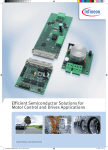
1
XMC 750 Watt Motor Control Application Kit Getting Started PMSM Motor Sensorless dual shunt Field Oriented Control (FOC) (PMSMFOCSL02) Agenda (1/2) Kit Overview Tooling Overview Getting Started Chapter 1: Generate PMSMFOCSL02 template Chapter 2: Configure CCU4 as Debugging feature Chapter 3: Motor Electrical Parameters Measurement Chapter 4: Driving Ventilation Fan Application Chapter 5: Driving Ceiling Fan Application 2014-09-26 Copyright © Infineon Technologies AG 2014. All rights reserved. Page 2 Agenda (2/2) Summary General Information References Where to find Apps documentation? Where to download example projects? How to load Example project in DAVE? How to improve compiler performance? 2014-09-26 Copyright © Infineon Technologies AG 2014. All rights reserved. Page 3 Agenda (1/2) Kit Overview Tooling Overview Getting Started Chapter 1: Generate PMSMFOCSL02 template Chapter 2: Configure CCU4 as Debugging feature Chapter 3: Motor Electrical Parameters Measurement Chapter 4: Driving Ventilation Fan Application Chapter 5: Driving Ceiling Fan Application 2014-09-26 Copyright © Infineon Technologies AG 2014. All rights reserved. Page 4 Kit Overview (1/3) XMC1300 Drive Card with galvanic isolation 2014-09-26 Copyright © Infineon Technologies AG 2014. All rights reserved. Page 5 Kit Overview (2/3) XMC4400 Drive Card with galvanic isolation 2014-09-26 Copyright © Infineon Technologies AG 2014. All rights reserved. Page 6 Kit Overview (3/3) 3 Phase Power Inverter 750W 2014-09-26 Copyright © Infineon Technologies AG 2014. All rights reserved. Page 7 Agenda (1/2) Kit Overview Tooling Overview Getting Started Chapter 1: Generate PMSMFOCSL02 template Chapter 2: Configure CCU4 as Debugging feature Chapter 3: Motor Electrical Parameters Measurement Chapter 4: Driving Ventilation Fan Application Chapter 5: Driving Ceiling Fan Application 2014-09-26 Copyright © Infineon Technologies AG 2014. All rights reserved. Page 8 Tooling Overview – Boot Modes (1/2) Boot Modes available UART Bootstrap-Loader Mode User Mode (Halt After Reset) User Mode (Debug) Default Mode of device on Drive Card User Mode (Productive) Boot Modes can be configured via: DAVE ― Download DAVE http://www.infineon.com/DAVE MemTool ― Download MemTool http://www.infineon.com/cms/en/product/channel.html?channel=ff80808112ab681d0112ab6b50fe07c9 For more information on how to configure the BMI value, please refer to the XMC1000 Tooling Guide. 2014-09-26 Copyright © Infineon Technologies AG 2014. All rights reserved. Page 9 Tooling Overview – DAVETM (2/2) Download DAVETM installer package from: http://www.infineon.com/cms/en/product/promopages/aim-mc/DAVE_3_Download.html Note: For users who have downloaded DAVETM as a zipped file package, DAVETM can be started via DAVE-*.exe in the eclipse folder. 2014-09-26 Copyright © Infineon Technologies AG 2014. All rights reserved. Page 10 Agenda (1/2) Kit Overview Tooling Overview Getting Started Chapter 1: Generate PMSMFOCSL02 template Chapter 2: Configure CCU4 as Debugging feature Chapter 3: Motor Electrical Parameters Measurement Chapter 4: Driving Ventilation Fan Application Chapter 5: Driving Ceiling Fan Application 2014-09-26 Copyright © Infineon Technologies AG 2014. All rights reserved. Page 11 Getting Started Following these steps to get started with XMC 750 Watt Motor Control Application Kit: 1. Read through Board Users Manual 3phase Power Inverter 750W 2. Connect the power board to a AC input power supply 3. Connect XMC1300 drive card to power board 4. Using the USB cable included in the kit with 750W Motor Control Application Kit. The user can program the Drive Card to drive the motor after connecting USB cable between a PC & kit 2014-09-26 Copyright © Infineon Technologies AG 2014. All rights reserved. Page 12 Block Diagram of Infineon Sensorless Field Oriented Control In general, FOC is a method to generate a 3-phase sinusoidal signal which can easily be controlled in frequency and amplitude in order to minimize the current which means to maximize the efficiency 2014-09-26 Copyright © Infineon Technologies AG 2014. All rights reserved. Page 13 Agenda (1/2) Kit Overview Tooling Overview Getting Started Chapter 1: Generate PMSMFOCSL02 template Chapter 2: Configure CCU4 as Debugging feature Chapter 3: Motor Electrical Parameters Measurement Chapter 4: Driving Ventilation Fan Application Chapter 5: Driving Ceiling Fan Application 2014-09-26 Copyright © Infineon Technologies AG 2014. All rights reserved. Page 14 Chapter 1: Generate PMSMFOCSL02 template (1/12) 1. Open DAVETM 3. 2. In DAVETM workspace, create a new “Empty Main” project: File->New->DAVE Project Give the project a name e.g. “PMSMFOCSL02_Example01” Select “DAVE CE Project” as Project Type 2014-09-26 Select the device accordingly, select “XMC1300-TO38X0200” as controller, depending on your hardware Copyright © Infineon Technologies AG 2014. All rights reserved. Page 15 Chapter 1: Generate PMSMFOCSL02 template (2/12) Click on “App Selection View” on your right 2014-09-26 Copyright © Infineon Technologies AG 2014. All rights reserved. Page 16 Chapter 1: Generate PMSMFOCSL02 template (3/12) Look for “PMSMFOCSL02” under App Selection View Click “OK” to create New Instance for ADC Double click on “PMSMFOCSL02” in the S/W App Connectivity View 2014-09-26 Copyright © Infineon Technologies AG 2014. All rights reserved. Page 17 Chapter 1: Generate PMSMFOCSL02 template (4/12) Configure PMSMFOCSL02 settings Open PMSMFOCSL02 UIEditor by double-clicking or right-click->UIEditor on the app in S/W Connectivity View Control Algorithm tab, ― Keep default settings 2014-09-26 Copyright © Infineon Technologies AG 2014. All rights reserved. Page 18 Chapter 1: Generate PMSMFOCSL02 template (5/12) Control Panel tab, In PMSMFOCSL02, motor run in open loop (V/F control) and switch to closed loop In open loop motor start with Start Speed Reference and ramp up the motor until speed reaches as Start Speed Threshold The control switch to closed loop at Start Speed Threshold The motor will ramp up until it reaches End Speed Reference Configuration Options: In Default Mode PI and V/F parameters will be calculated based on motor parameters. Select User Defined to fine-tune Use For V/F Start-up only 2014-09-26 Copyright © Infineon Technologies AG 2014. All rights reserved. Page 19 Chapter 1: Generate PMSMFOCSL02 template (6/12) Motor Parameters tab, ― Parameters can be found in motor datasheet ― User can measure motor Phase to Phase Resistance/Inductance manually by own measurement devices ― Refer to Chapter 3 for Motor Electrical Parameter Measurement 2014-09-26 Copyright © Infineon Technologies AG 2014. All rights reserved. Page 20 Chapter 1: Generate PMSMFOCSL02 template (7/12) Power Board tab, ― Dead Time and Switch Delay is set to 750ns and 800ns. ― The gate driver (6EDL04I06NT) is negative logic, user need to set Passive Level Configuration to HIGH. ― The gate driver enable signal is inverted in order to provide active low ― User may refer to Board Users Manual 750W to check the power board behavior for more info. XMC1300 VADC = 5V DC link voltage divider ratio 2014-09-26 Copyright © Infineon Technologies AG 2014. All rights reserved. Page 21 Chapter 1: Generate PMSMFOCSL02 template (8/12) Label the apps instance, Under App Dependency TreeView ― Right click on IO002/0 app -> Add User Label ― Type U_H in the field provided Repeat the steps to label other apps App Feature IO002/0 [U_H] High side Phase U IO002/1 [U_L] Low side Phase U IO002/2 [V_H] High side Phase V IO002/3 [V_L] Low side Phase V IO002/4 [W_H] High side Phase W IO002/5 [W_L] Low side Phase W IO004/0 [Enable_Pin] Enable Pin Gate Driver IC IO002/6 [Trap_Pin] Trap Pin IO001/0 [I_U] Current Phase U IO001/1 [I_V] Current Phase V 2014-09-26 Copyright © Infineon Technologies AG 2014. All rights reserved. Page 22 Chapter 1: Generate PMSMFOCSL02 template (9/12) Manual Pin Assignment for XMC1300 Drive Card, Assign Pin ― ― ― ― Click Assign Pins accordingly Solve and Save Close App Pin Number IO002/0 [U_H] P0.0 IO002/1 [U_L] P0.1 IO002/2 [V_H] P0.7 IO002/3 [V_L] P0.6 IO002/4 [W_H] P0.8 IO002/5 [W_L] P0.9 IO004/0 [Enable_Pin] P0.11 IO002/6 [Trap_Pin] P0.12 IO001/0 [I_U] P2.9 IO001/1 [I_V] P2.10 2014-09-26 Copyright © Infineon Technologies AG 2014. All rights reserved. Page 23 Chapter 1: Generate PMSMFOCSL02 template (10/12) To Generate Code, Click Start the motor by calling the API function PMSMFOCSL02_MotorStart(&PMSMFOCSL02_Handle0) in Main.c 2014-09-26 Copyright © Infineon Technologies AG 2014. All rights reserved. Page 24 Chapter 1: Generate PMSMFOCSL02 template (11/12) Optimize DAVE generated code: 1. Go to Project -> Active Project Properties 2. Under ARM-GCC C Compiler -> Optimization – Optimize most (O3) 3. Under ARM-GCC Linker -> General -> enable Remove unused section 2014-09-26 Copyright © Infineon Technologies AG 2014. All rights reserved. Page 25 Chapter 1: Generate PMSMFOCSL02 template (12/12) Build project 1. Click 2. Wait for Build to finish Code Size: 15.5K Download code 1. Click 2. First time download, double Tasking C/C++ Debugger in Debug Configuration 3. Select Infineon Boot Kit for XMC1300 and click Debug 4. Click 2014-09-26 Copyright © Infineon Technologies AG 2014. All rights reserved. Page 26 Agenda (1/2) Kit Overview Tooling Overview Getting Started Chapter 1: Generate PMSMFOCSL02 template Chapter 2: Configure CCU4 as Debugging feature Chapter 3: Motor Electrical Parameters Measurement Chapter 4: Driving Ventilation Fan Application Chapter 5: Driving Ceiling Fan Application 2014-09-26 Copyright © Infineon Technologies AG 2014. All rights reserved. Page 27 Chapter 2: Configure CCU4 as Debugging feature (1/7) The feature enable the user to visualize and analyze real-time variables, facilitating control loop adjustment Function of CCU4_Debug3Output(): User can use P0.4, P0.5 and P1.2 on HW board to output variables through PWM duty cycle change 1. Set Oscilloscope Acquisition Mode (Press [Acquire] key on the front panel) to “High Resolution” mode (oscilloscope effectively acts like a low-pass filter) √ 2. Or, use RC filters to attenuate HF 2014-09-26 Copyright © Infineon Technologies AG 2014. All rights reserved. Page 28 Chapter 2: Configure CCU4 as Debugging feature (2/7) User may SKIP the steps if debugging feature is not required ln04 is positive integer Tmp_CRS = 2014-09-26 𝑰𝒏𝟎𝟒 𝟐𝑵 * CCU4_PWM_PERIOD Copyright © Infineon Technologies AG 2014. All rights reserved. Page 29 Chapter 2: Configure CCU4 as Debugging feature (3/7) ln04 is either positive or negative integer Tmp_CRS = 2014-09-26 𝑰𝒏𝟎𝟒 𝟐𝑵+𝟏 * CCU4_PWM_PERIOD Copyright © Infineon Technologies AG 2014. All rights reserved. Page 30 Chapter 2: Configure CCU4 as Debugging feature (4/7) Tmp_CRS= 𝐼𝑛04 2𝐼𝑛04_𝑁 × 𝐶𝐶𝑈4_𝑃𝑊𝑀_𝑃𝐸𝑅𝐼𝑂𝐷 (𝐼𝑛04+ 2𝑙𝑛04_𝑁 ) Tmp_CRS = × 𝐶𝐶𝑈4_𝑃𝑊𝑀_𝑃𝐸𝑅𝐼𝑂𝐷 2𝑁+1 Set 1 if sample +ve and –ve signals Variable Name 2014-09-26 Scale it to 29 Copyright © Infineon Technologies AG 2014. All rights reserved. Page 31 Chapter 2: Configure CCU4 as Debugging feature (5/7) 1. Initialize the CCU4 PWM period to 100Khz, 50% duty cycle 2. Configure 3 I/O on board as CCU4 outputs P0.5 – CCU40.OUT0 P0.4 – CCU40.OUT1 P1.2 – CCU40.OUT2 3. Create software handle function in Main.c 4. Call CCU4_Init() to initialize CCU4 configuration before start the motor operation 5. Call the CCU4_Debug3Output() to sample desire signals in PMSMFOCSL02_PWMPeriodMatchISR0(). PMSMFOCSL02_Handle0.H_Ptr->Ialpha PMSMFOCSL02_Handle0.H_Ptr->Ibeta PMSMFOCSL02_Handle0.H_Ptr->Angle 2014-09-26 Copyright © Infineon Technologies AG 2014. All rights reserved. Page 32 Chapter 2: Configure CCU4 as Debugging feature (6/7) 1. To avoid DAVE3 erase user function when user click Regenerate code, please go to: Model -> PMSMFOCSL02 -> 1.0.6 -> Templates -> PMSMFOCSL02c.jet Paste the user function into PMSMFOCSL02_PWMPeriodMatchISR0() in PMSMFOCSL02c.jet, click SAVE and CLOSE it. 2. Copy the content of attached main.c, and paste to user DAVE generated main.c 3. Save and close the PMSMFOCSL02c.jet 2014-09-26 Copyright © Infineon Technologies AG 2014. All rights reserved. Page 33 Chapter 2: Configure CCU4 as Debugging feature (7/7) Click to regenerate code after modifying *.jet file, with Solve and re-generate code then click OK Now CCU4Debug3Output() has been included in PMSMFOCSL02.c under PMSMFOCSL02_PWMPeriodMatchISR0() 2014-09-26 Copyright © Infineon Technologies AG 2014. All rights reserved. Page 34 Agenda (1/2) Kit Overview Tooling Overview Getting Started Chapter 1: Generate PMSMFOCSL02 template Chapter 2: Configure CCU4 as Debugging feature Chapter 3: Motor Electrical Parameters Measurement Chapter 4: Driving Ventilation Fan Application Chapter 5: Driving Ceiling Fan Application 2014-09-26 Copyright © Infineon Technologies AG 2014. All rights reserved. Page 35 Chapter 3: Motor Electrical Parameters Measurement (1/4) The proposed measurement techniques determine: Number of pole pairs Phase to phase stator resistances, inductances The electrical parameters are needed to be configured in DAVE apps to calculate torque, flux PI controller and etc 2014-09-26 Copyright © Infineon Technologies AG 2014. All rights reserved. Page 36 Chapter 3: Motor Electrical Parameters Measurement (2/4) Equipments required to measure motor pole pairs: Driving motor Oscilloscope, voltage probe Following steps describe the method to determine number of motor pole pairs: 1. Connect the Phase U to signal probe, phase V/Phase W to ground 2. Rotate the motor manually in 1 mechanical revolution (360˚) and capture the waveform in oscilloscope 1 2 3 Phase U Back EMF Phase U 0˚ 2014-09-26 Phase V/W Copyright © Infineon Technologies AG 2014. All rights reserved. Page 37 Chapter 3: Motor Electrical Parameters Measurement (3/4) The number of pole pairs = 3 The number of pole pairs can be obtained from the motor specification sheet. Using measured frequency value, the speed can be calculated using below equation: Speed (RPM) = 2014-09-26 𝟔𝟎 𝒙 𝑭𝒓𝒆𝒒𝒖𝒆𝒏𝒄𝒚 𝒎𝒆𝒂𝒔𝒖𝒓𝒆𝒅 𝒊𝒏 𝑯𝒆𝒓𝒕𝒛 𝒏𝒐.𝑷𝒐𝒍𝒆 𝑷𝒂𝒊𝒓𝒔 Copyright © Infineon Technologies AG 2014. All rights reserved. Page 38 Chapter 3: Motor Electrical Parameters Measurement (4/4) Equipment required to measure phase to phase stator resistances and inductances: Digital Multimeter /LCR meter Following steps describe the method to measure phase to phase resistances and inductances: Phase to Phase Resistance – Use multimeter and measure the DC resistance across the two phase wires of PMSM. Phase to Phase Inductance – Use LCR to measure the inductance at 1Khz across the two phase wires of PMSM 2014-09-26 Copyright © Infineon Technologies AG 2014. All rights reserved. Page 39 Agenda (1/2) Kit Overview Tooling Overview Getting Started Chapter 1: Generate PMSMFOCSL02 template Chapter 2: Configure CCU4 as Debugging feature Chapter 3: Motor Electrical Parameters Measurement Chapter 4: Driving Ventilation Fan Application Chapter 5: Driving Ceiling Fan Application 2014-09-26 Copyright © Infineon Technologies AG 2014. All rights reserved. Page 40 Chapter 4: Driving Ventilation Fan Application (1/17) Ventilation Fan Application Overview: Microcontroller: Infineon XMC1302-T038X0200 Algorithm: Dual Shunt Sensorless FOC (PMSMFOCSL02) Hardware: XMC 750 Watt Motor Control Application Kit (KIT_XMC750WATT_MC_AK_V1 ) DC Link Voltage: 320 VDC Fan Motor Specification: Phase to Phase Resistance: 19.6 Ω Phase to Phase Inductance: 154 mH ~ 174 mH Pole Pairs: 3 Tested Speed range: 500 rpm to 1000 rpm 2014-09-26 Copyright © Infineon Technologies AG 2014. All rights reserved. Page 41 Chapter 4: Driving Ventilation Fan Application (2/17) This chapter provides a guideline on how to run ventilation Fan application using PMSMFOCSL02 TP1, TP2 and TP3 are test points to probe with oscilloscope Connect the motor phases to XMC 750 Watt Motor Control Application Kit as shown: TP = Test Point 230Vac/50Hz P0.4 (TP1) PC USB P0.5 MCU CTRL (TP2) FAN Motor 2014-09-26 Copyright © Infineon Technologies AG 2014. All rights reserved. P1.2 (TP3) Page 42 Chapter 4: Driving Ceiling Fan Application (3/17) 2014-09-26 Copyright © Infineon Technologies AG 2014. All rights reserved. Page 43 Chapter 4: Driving Ceiling Fan Application (4/17) 2014-09-26 Copyright © Infineon Technologies AG 2014. All rights reserved. Page 44 Chapter 4: Driving Ventilation Fan Application (5/17) 1. Create DAVE CE project - (page 15) 2. Configure Pin Assignment – (page 23) 3. Configure Motor, power board, control profile parameters in DAVE GUIs Keep default setting value in Control Algorithm tab Click on Motor Parameters tab, 2014-09-26 Configure Motor Nominal Voltage as 320V Nominal Speed set to 1000 rpm Phase to phase resistance set to 19.6 Ω Phase to phase inductance set to 164 mH Pole Pairs of motor = 3 Copyright © Infineon Technologies AG 2014. All rights reserved. Page 45 Chapter 4: Driving Ventilation Fan Application (6/17) Click on Power Board tab, 2014-09-26 Refer to page 16 or 750W Board User Manual for hardware details Copyright © Infineon Technologies AG 2014. All rights reserved. Page 46 Chapter 4: Driving Ventilation Fan Application (7/17) Click on Control Panel tab, user should configure start-up parameters for V/F control 2014-09-26 Copyright © Infineon Technologies AG 2014. All rights reserved. Page 47 Chapter 4: Driving Ventilation Fan Application (8/17) 4. Generate Application Code Template – click 5. Configure CCU4 as Debugging Feature – (page 27 – page 29) Copy the attached main.c and paste into user’s main.c 6. Fine-tuning Start-up in V/F control V/F control principle consist in feeding the motor winding with a 3phase sinusoidal voltage whose amplitude is proportional to the frequency and time. Under C/C++ projects -> Dave -> Generated -> src -> PMSMFOCSL02.c, search for PMSMFOCSL02_SpeedRampup() API function. Grey out the 5 code lines as shown: 2014-09-26 Copyright © Infineon Technologies AG 2014. All rights reserved. Page 48 Chapter 4: Driving Ventilation Fan Application (9/17) Place 3 signal probes on P0.4, P0.5, P1.2 on hardware Take note that the start-up current would be HIGH if user configure motor start-up parameters wrongly. User can always limit the current in power supply It’s recommended to start with LOW V/F constant & Voltage Offset. (V/F constant = 1.0 V/Hz, Voltage Offset = 1000 mV) The start-up response will be affected by Speed Slew Rate, Start Speed Threshold, V/F Constant, Voltage Offset 2014-09-26 Copyright © Infineon Technologies AG 2014. All rights reserved. Page 49 Chapter 4: Driving Ventilation Fan Application (10/17) 7. Evaluate the motor start-up response, repeat fine-tuning steps if necessary. User may reconfigure the 4 parameters in App GUI, regenerate code is needed for every changes in GUI 2014-09-26 Copyright © Infineon Technologies AG 2014. All rights reserved. Page 50 Chapter 4: Driving Ventilation Fan Application (11/17) User may change the RED highlighted variables to improve the startup response in PMSMFOCSL02_Config.c The main advantage: Save up compilation time during fine-tuning 2014-09-26 Refer to page 25 to set code optimization level in DAVE before user download hex code into XMC1300 Copyright © Infineon Technologies AG 2014. All rights reserved. Page 51 Chapter 4: Driving Ventilation Fan Application (12/17) Below shows CCU4 output waveform of Ventilation Fan while running in V/F control Start-up Motor Speed = 100 rpm Channel 1 (yellow):- PMSMFOCSL02_Handle0.H_Ptr-> 𝐼𝛼 Channel 2 (green): - PMSMFOCSL02_Handle0.H_Ptr -> Iu Channel 3 (blue): - PMSMFOCSL02_Handle0.H_Ptr -> Angle Channel 4 (pink): Current of fan motor Phase U (measured by current probe, 0.1V/A) 2014-09-26 Copyright © Infineon Technologies AG 2014. All rights reserved. Page 52 Chapter 4: Driving Ventilation Fan Application (13/17) Screenshot of typical V/F parameters value in DAVE App The Start-up parameters shown are mainly for references purpose. Due to differences between various motor, the V/F control parameters needs to be tuned to drive every new motor model 2014-09-26 Copyright © Infineon Technologies AG 2014. All rights reserved. Page 53 Chapter 4: Driving Ventilation Fan Application (14/17) 8. The FOC Closed Loop operation can be ENABLED by uncommenting the 5 lines highlighted as below: Under C/C++ projects -> Dave -> Generated -> src -> PMSMFOCSL02.c, search for PMSMFOCSL02_SpeedRampup() API function. Skip the following page 50 to page 52 if user is using PMSMFOCSL02[1.0.8] and above Id and Iq KpKI values in App GUI are calculated based on motor resistance and inductance values. Speed PI Kp and KI are not calculated, it is hardcoded values. 2014-09-26 Copyright © Infineon Technologies AG 2014. All rights reserved. Page 54 Chapter 4: Driving Ventilation Fan Application (15/17) Build project (At this stage, the motor will be driven in FOC Closed Loop mode 1. Click Download code 1. Click 2014-09-26 , Wait for Build to finish & click to run the motor Copyright © Infineon Technologies AG 2014. All rights reserved. Page 55 Chapter 4: Driving Ventilation Fan Application (16/17) 9. Below shows CCU4 output waveforms of Ventilation Fan while from V/F Open Loop to FOC Closed loop V/F Control Start-up Transition Open Loop to Closed Loop at 100 rpm Transition at 11W Channel 1 (yellow):- PMSMFOCSL02_Handle0.H_Ptr-> 𝐼𝛼 Channel 2 (green): - PMSMFOCSL02_Handle0.H_Ptr -> Iu Channel 3 (blue): - PMSMFOCSL02_Handle0.H_Ptr -> Angle Channel 4 (pink): Current of fan motor Phase U (measured by current probe, 0.1V/A) 2014-09-26 Copyright © Infineon Technologies AG 2014. All rights reserved. Page 56 Chapter 4: Driving Ventilation Fan Application (17/17) 10. Below shows CCU4 output waveforms of Ventilation Fan running in FOC during steady state End Speed Reference = 1000 rpm Speed Slew Rate = 30 rpm/s Speed = 60 𝑥 51 𝐻𝑧 3 = 1020 𝑟𝑝𝑚 Channel 1 (yellow):- PMSMFOCSL02_Handle0.H_Ptr-> 𝐼𝛼 Channel 2 (green): - PMSMFOCSL02_Handle0.H_Ptr -> Iu Channel 3 (blue): - PMSMFOCSL02_Handle0.H_Ptr -> Angle Channel 4 (pink): Current of fan motor Phase U (measured by current probe, 0.1V/A) 2014-09-26 Copyright © Infineon Technologies AG 2014. All rights reserved. Page 57 Agenda (1/2) Kit Overview Tooling Overview Getting Started Chapter 1: Generate PMSMFOCSL02 template Chapter 2: Configure CCU4 as Debugging feature Chapter 3: Motor Electrical Parameters Measurement Chapter 4: Driving Ventilation Fan Application Chapter 5: Driving Ceiling Fan Application 2014-09-26 Copyright © Infineon Technologies AG 2014. All rights reserved. Page 58 Chapter 5: Driving Ceiling Fan Application (1/20) Ceiling Fan Application Overview: Microcontroller: Infineon XMC1302-T038X0200 Algorithm: Dual Shunt Sensorless FOC (PMSMFOCSL02) Hardware: XMC 750 Watt Motor Control Application Kit (KIT_XMC750WATT_MC_AK_V1 ) DC Link Voltage: 320 VDC Fan Motor Specification: Phase to Phase Resistance: 71.2 Ω Phase to Phase Inductance: 483 mH ~ 174 mH Pole Pairs: 6 Tested Speed range: 30 rpm to 220 rpm Blade Size: 22.5” 2014-09-26 Copyright © Infineon Technologies AG 2014. All rights reserved. Page 59 Chapter 5: Driving Ceiling Fan Application (2/20) This chapter provides a guideline on how to run Ceiling Fan application using PMSMFOCSL02 TP1, TP2 and TP3 are test points to probe with oscilloscope Connect the motor phases to XMC 750 Watt Motor Control Application Kit as shown: TP = Test Point 230Vac/50Hz P0.4 (TP1) PC USB P0.5 MCU CTRL (TP2) FAN Motor 2014-09-26 Copyright © Infineon Technologies AG 2014. All rights reserved. P1.2 (TP3) Page 60 Chapter 5: Driving Ceiling Fan Application (3/20) 2014-09-26 Copyright © Infineon Technologies AG 2014. All rights reserved. Page 61 Chapter 5: Driving Ceiling Fan Application (4/20) 2014-09-26 Copyright © Infineon Technologies AG 2014. All rights reserved. Page 62 Chapter 5: Driving Ceiling Fan Application (5/20) 1. Create DAVE CE project - (page 15) 2. Configure Pin Assignment – (page 23) 3. Configure Motor, power board, control profile parameters in DAVE GUI Keep default setting value in Control Algorithm tab Click on Motor Parameters tab, 2014-09-26 Configure Motor Nominal Voltage as 320V Nominal Speed set to 300 rpm Phase to phase resistance set to 71.2Ω Phase to phase inductance set to 483mH Pole Pairs of motor = 6 Copyright © Infineon Technologies AG 2014. All rights reserved. Page 63 Chapter 5: Driving Ceiling Fan Application (6/20) Click on Power Board tab, 2014-09-26 Refer to page 16 or 750W Board User Manual for hardware details Copyright © Infineon Technologies AG 2014. All rights reserved. Page 64 Chapter 5: Driving Ceiling Fan Application (7/20) Click on Control Panel tab, user should configure start-up parameters for V/F control Starting with lower start-up power 2014-09-26 Copyright © Infineon Technologies AG 2014. All rights reserved. Page 65 Chapter 5: Driving Ceiling Fan Application (8/20) 4. Generate Application Code Template – Click 5. Configure CCU4 as Debugging Feature – (page 27 – page 29) Following the steps to enable CCU4 debugging pin Copy the attached main.c and paste into user’s main.c 6. Fine-tuning Start-up in V/F control V/F control principle consist in feeding the motor winding with a 3phase sinusoidal voltage whose amplitude is proportional to the frequency and time. Under C/C++ projects -> Dave -> Generated -> src -> PMSMFOCSL02.c, search for PMSMFOCSL02_SpeedRampup() API function. Grey out the 5 code lines as shown: 2014-09-26 Copyright © Infineon Technologies AG 2014. All rights reserved. Page 66 Chapter 5: Driving Ceiling Fan Application (9/20) Place 3 signal probes on P0.4, P0.5, P1.2 on hardware Take note that the start-up current would be HIGH if user configure motor start-up parameters wrongly. User can always limit the current in power supply It’s recommended to start with LOW V/F constant & Voltage Offset. (V/F constant = 1.0 V/Hz, Voltage Offset = 1000 mV) The start-up response will be affected by Speed Slew Rate, Start Speed Threshold, V/F Constant, Voltage Offset 2014-09-26 Copyright © Infineon Technologies AG 2014. All rights reserved. Page 67 Chapter 5: Driving Ceiling Fan Application (10/20) 7. Evaluate the motor start-up response, repeat fine-tuning steps if necessary. User may reconfigure the 4 parameters in App GUI, regenerate code is needed for every changes in GUI 2014-09-26 Copyright © Infineon Technologies AG 2014. All rights reserved. Page 68 Chapter 5: Driving Ceiling Fan Application (11/20) User may change the RED highlighted variables to improve the start-up response The main advantage: Save up compilation time during fine-tuning High inertia motor requires higher start-up power 2014-09-26 Refer to page 21 to set code optimization level in DAVE before user download hex code into XMC1300 Copyright © Infineon Technologies AG 2014. All rights reserved. Page 69 Chapter 5: Driving Ceiling Fan Application (12/20) Below shows CCU4 output waveform of Ventilation Fan while running in V/F control Start-up Motor Speed = 30 rpm Channel 1 (yellow):- PMSMFOCSL02_Handle0.H_Ptr-> 𝐼𝛼 Channel 2 (green): - PMSMFOCSL02_Handle0.H_Ptr -> Iu Channel 3 (blue): - PMSMFOCSL02_Handle0.H_Ptr -> Angle Channel 4 (pink): Current of fan motor Phase U (measured by current probe, 0.1V/A) 2014-09-26 Copyright © Infineon Technologies AG 2014. All rights reserved. Page 70 Chapter 5: Driving Ceiling Fan Application (13/20) Screenshot of typical V/F parameters value in DAVE App The Start-up parameters shown are mainly for references purpose. Due to differences between various motor, the V/F control parameters needs to be tuned to drive every new motor model 2014-09-26 Copyright © Infineon Technologies AG 2014. All rights reserved. Page 71 Chapter 5: Driving Ceiling Fan Application (14/20) 8. The FOC Closed Loop operation can be ENABLED by uncommenting the 5 lines highlighted as below: Under C/C++ projects -> Dave -> Generated -> src -> PMSMFOCSL02.c, search for PMSMFOCSL02_SpeedRampup() API function. Skip the following page 50 to page 52 if user is using PMSMFOCSL02[1.0.8] and above Id and Iq KpKI values in App GUI are calculated based on motor resistance and inductance values. Speed PI Kp and KI are not calculated, it is hardcoded values. 2014-09-26 Copyright © Infineon Technologies AG 2014. All rights reserved. Page 72 Chapter 5: Driving Ceiling Fan Application (15/20) 9. Fine-tune PT12 Filter Constant for better performance The integration of the induced voltage during the calculation of the flux Ψ is calculated by a low pass filter of first order which is realized by a PT12 controller. Given PT12 controller formula as: Y[n] = Y[n-1] + Z1 * X[n] – Z2 * Y[n-1] For example, assume X[1] = 1, user can fine-tune the Z1 value and Z2 value. The response time can be modified. Z1 = 6367, Z2 = 636 2014-09-26 Z1 = 636, Z2 = 63 Copyright © Infineon Technologies AG 2014. All rights reserved. Page 73 Chapter 5: Driving Ceiling Fan Application (16/20) User would require to modify the PMSMFOCSL02_Config.c to change the response time to drive different motors. To fine-tune the PT12 filter gain, additional user code needs to be added as shown below: 2014-09-26 User can fine-tune Z1_MULTIPLY variable for other PMSM motors. Copyright © Infineon Technologies AG 2014. All rights reserved. Page 74 Chapter 5: Driving Ceiling Fan Application (17/20) Besides, user needs to change -2 to -4 for both PMSMFOCSL02_Handle0.H_Ptr->Ia and PMSMFOCSL02_Handle0.H_Ptr->Ib in PMSMFOCSL02.c 2014-09-26 Copyright © Infineon Technologies AG 2014. All rights reserved. Page 75 Chapter 5: Driving Ceiling Fan Application (18/20) 10. In this stage, the motor will be driven in FOC Closed Loop. Build project 1. Click , Wait for Build to finish Download code 1. Click 2014-09-26 & click to run the motor User should monitor the transition current waveform to fine-tune Z1_MULTIPLY to reduce vibration, current spike and etc Copyright © Infineon Technologies AG 2014. All rights reserved. Page 76 Chapter 5: Driving Ceiling Fan Application (19/20) Below shows CCU4 output waveforms of Ceiling Fan while from V/F Open Loop to FOC Closed loop V/F Control Start-up Transition Open Loop to Closed Loop at 30 rpm Channel 1 (yellow):- PMSMFOCSL02_Handle0.H_Ptr-> 𝐼𝛼 Channel 2 (green): - PMSMFOCSL02_Handle0.H_Ptr -> Iu Channel 3 (blue): - PMSMFOCSL02_Handle0.H_Ptr -> Angle Channel 4 (pink): Current of fan motor Phase U (measured by current probe, 0.1V/A) 2014-09-26 Copyright © Infineon Technologies AG 2014. All rights reserved. Page 77 Chapter 5: Driving Ceiling Fan Application (20/20) Below shows CCU4 output waveforms of Ceiling Fan running in FOC during steady state End Speed Reference = 220 rpm Speed Slew Rate = 13 rpm/s Speed = 60 𝑥 22.7 𝐻𝑧 6 = 227 𝑟𝑝𝑚 Channel 1 (yellow):- PMSMFOCSL02_Handle0.H_Ptr-> 𝐼𝛼 Channel 2 (green): - PMSMFOCSL02_Handle0.H_Ptr -> Iu Channel 3 (blue): - PMSMFOCSL02_Handle0.H_Ptr -> Angle Channel 4 (pink): Current of fan motor Phase U (measured by current probe, 0.1V/A) 2014-09-26 Copyright © Infineon Technologies AG 2014. All rights reserved. Page 78 Agenda (2/2) Summary General Information References Where to find Apps documentation? Where to download example projects? How to load Example project in DAVE? How to improve compiler performance? 2014-09-26 Copyright © Infineon Technologies AG 2014. All rights reserved. Page 79 Summary This document provides effective techniques for tuning the PMSMFOCSL02 App in DAVE for running high voltage PMSM motor This procedure are more robust and should cover the requirements of most ventilation fan and ceiling fan applications 2014-09-26 Copyright © Infineon Technologies AG 2014. All rights reserved. Page 80 Agenda (2/2) Summary General Information References Where to find Apps documentation? Where to download example projects? How to load Example project in DAVE? 2014-09-26 Copyright © Infineon Technologies AG 2014. All rights reserved. Page 81 General Information Where to buy kit: http://www.ehitex.de/XMC-750-Watt-Motor-Control-ApplicationKit_detail_469.html Order Number: KIT_XMC750WATT_MC_AK_V1 Kit documentation: KIT_XMC750WATT_MC_AK_V1 Infineon parts utilized on kit: Infineon Parts Order Number XMC1300 Microcontroller XMC1302-T038X-0200 LDO 500mA IFX1763 Standalone PFC Controller ICE3PCS02 Offline SMPS Current Mode Controller ICE3B0365JG (Discontinued) ICE3BR4765JG (Replacement) Gate Drive IC 6ED003L06-F High Speed DuoPack IGBT IKB20N60H3 IGBT with integrated diode IKD10N60R 2014-09-26 Copyright © Infineon Technologies AG 2014. All rights reserved. Page 82 Agenda (2/2) Summary General Information References Where to find Apps documentation? Where to download example projects? How to load Example project in DAVE? How to improve compiler performance? 2014-09-26 Copyright © Infineon Technologies AG 2014. All rights reserved. Page 83 References – Where to find App Documentation? Go to Help -> Help Contents Go to DAVE Apps -> Expand topics -> Clck on IO004 (latest version) Click on IO004 App -> Overview Usage information found under xx App -> “Deployment and usage view” 2014-09-26 Copyright © Infineon Technologies AG 2014. All rights reserved. Page 84 References – Where to download Example Projects? (1/2) Two sets of Example Projects available Additional Application Examples ― Can be downloaded directly from the web DAVETM Project Library Examples ― Can be downloaded from library in DAVETM ― Can also be downloaded directly from the web 2014-09-26 Copyright © Infineon Technologies AG 2014. All rights reserved. Page 85 References – Where to download Example Projects? (2/2) Additional Application Examples available Running LEDs Example (Simple_XMC1100_RunningLEDs.zip) UART Example (Simple_XMC1100_UART.zip) 2014-09-26 Copyright © Infineon Technologies AG 2014. All rights reserved. Page 86 References – How to load Example Project in DAVETM? (1/5) Download Example Projects via DAVETM library store Help Install DAVE Example Library 2014-09-26 Copyright © Infineon Technologies AG 2014. All rights reserved. Page 87 References – How to load Example Project in DAVETM? (2/5) Select DAVE Project Library Manager in the drop-down menu 2014-09-26 Copyright © Infineon Technologies AG 2014. All rights reserved. Page 88 References – How to load Example Project in DAVETM? (3/5) Select Examples in the Libraries window and click Next 2014-09-26 Copyright © Infineon Technologies AG 2014. All rights reserved. Page 89 References – How to load Example Project in DAVETM? (4/5) Accept terms of the license agreements and click Finish DAVE Example Projects are installed 2014-09-26 Copyright © Infineon Technologies AG 2014. All rights reserved. Page 90 References – How to load Example Project in DAVETM? (5/5) Download Example Projects from the web http://www.infineon.com/cms/en/product/promopages/aim-mc/dave_downloads.html Download the project zip file Download the project zip file Open DAVE™ and go to File Import Infineon DAVE Project Check “Select Archive File” Browse to the downloaded DAVE project zip file Press “Open” Home 2014-09-26 Copyright © Infineon Technologies AG 2014. All rights reserved. Page 91 References – How to improve compiler performance? Please refer to Infineon official XMC forum to explore how to speed up DAVE compilation time. It provides a couple of options that give perceivable improved speed. How to improve compiling feature discussion thread: http://www.infineonforums.com/threads/1647-Improve-compilerperformance 2014-09-26 Copyright © Infineon Technologies AG 2014. All rights reserved. Page 92