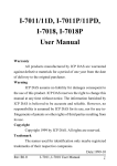
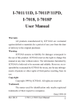
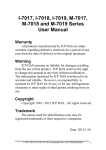
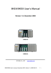
1
DCON for DASYLab DCON Remote I/O Modules Driver for DASYLab User Manual Warranty All products manufactured by ICP DAS are warranted against defective materials for a period of one year from the date of delivery to the original purchaser. Warning ICPDAS assumes no liability for damages consequent to the use of this product. ICP DAS reserves the right to change this manual at any time without notice. The information furnished by ICP DAS is believed to be accurate and reliable. However, no responsibility is assumed by ICP DAS for its use, not for any infringements of patents or other rights of third parties resulting from its use. Copyright Copyright 2004 by ICP DAS. All rights are reserved. Trademark The names used for identification only may be registered trademarks of their respective companies. DCON diver for DASYLab user manual (Ver1.2, Oct/2005 ) ---------1 Table of Content 1. DASYLab Introduction .............................................................3 1.1. Product List For DASYLab ......................................................... 4 2. DCON Driver Installation..........................................................5 3. Configuration ...........................................................................6 3.1. 3.2. Configuration of the modules ..................................................... 6 Configuration of the Serial Port .................................................. 8 4. Demo Application ...................................................................13 DCON diver for DASYLab user manual (Ver1.2, Oct/2005 ) ---------2 1. DASYLab Introduction DASYLab is popular and an Easy-To-Use software in the Data Acquisition System with all kinds of interfaces to connect to the hardware, such as to the RS232, IEEE USB, Parallel port, ISA bus, PCI bus, and so on. Furthermore, a variety of functional modules for measurement and control are supplied by DASYLab. For DCON remote I/O modules, users only need to install the drivers from ICPDAS. Thus the I-7000 series modules can be applied to the environments of measurement and control by using DASYLab. The following section is part of an application interface by DASYLab along with it’s bundled driver. DASYLab6-Net -Cycle memory.DSB - [Worksheet] Figure 1.1 DASYLab Worksheet DCON diver for DASYLab user manual (Ver1.2, Oct/2005 ) ---------3 1.1. Product List for DASYLab The following table displays some of the current products supported by ICPDAS remote I/O modules for use with DASYLab software. It includes AD/DA, digital I/O and Counter modules. If users want to find out more information about ICPDAS remote I/O modules, please visit the ICPDAS website (http://www.icpdas.com). Table 1.1 Current supported products for ICPDAS remote I/O modules. Module Type Digital I/O Counter Description Provides Digital Input, Output or Counter functions. Analog Input Provides Analog Input Analog Output Provides Analog Output Card Model I-7041, I-7042, I-7043, I-7044, I-7050, I-7052, I-7053, I-7055, I-7060, I-7063, I-7065, I-7067, I-7080 I-7005,I-7011, I-7011P, I-7012, I-7013, I-7014, I-7016, I-7017, I-7018, I-7018P, I-7033,I-7015 , I-7016/D , I-7019R I-7021, I-7022, I-7024 DCON diver for DASYLab user manual (Ver1.2, Oct/2005 ) ---------4 2. DCON Driver Installation Before using the DCON remote I/O modules in DASYLab 8x, please refer to the following steps in order to correctly install the DCON driver for DASYLab. Step 1. Download the driver “DCON_DASYLab.exe” from the ICPDAS website: http://www.icpdas.com/products/Software/DASYLab/download_1.htm Step 2. Execute the DCON_DASYLab.exe to extract the install files. Step 3. Execute Setup.exe to install the DCON driver into DASYLab. Step 4. Open the DASYLab 8x environment and the “ICP-CON” folder will be added into the menu bar as follows. Step 5. After completing the above steps, please refer to next chapter to set the configurations for the serial ports and modules. Then you can start to use the I-7000 series modules in DASYLab. DCON diver for DASYLab user manual (Ver1.2, Oct/2005 ) ---------5 3. Configuration 3.1. Configuration of the modules Users need to set up the baud rate, check sum, address of the hardware modules via the “DCON Utility” software provided by ICPDAS. For information on how to use the DCON Utility, please refer to the GetStart.pdf. (http://www.icpdas.com/download/7000/manual.htm). Note: Users can download the DCON Utility from the ICPDAS website: http://www.icpdas.com/download/7000/7000.htm Address : All modules connected to the same interface must be set to different addresses to become unambiguously identified in the network. The default setting is set to address 1. Always use addresses greater than 1. So you will be able to add new modules without any problems into your network. DCON diver for DASYLab user manual (Ver1.2, Oct/2005 ) ---------6 Baud Rate The baud rates for all hardware modules connected to one interface have to be the same. So, if you want to change the baud rate, only one module is allowed to be connected to the interface. Moreover, the pin Default (INT*) of the module has to be connected to the ground (B) GND. Otherwise the commands to change the baud rate will not be accepted. The Default setting is at the 9600 baud rate. Check Sum For each I-7000 series module, you can enable the check sum option to verify communication with the module. If an error occurs in the data flow, a check sum error is generated and the transferred data will be skipped. In the hardware driver this option is automatically used, if the module is configured to use check sums. To change the Baud rate or activate the check sum option, the pin Default (INT*) of the module has to be connected with the ground (B) GND. DCON diver for DASYLab user manual (Ver1.2, Oct/2005 ) ---------7 3.2. Serial Port Configuration The interfaces used by the I-7000 series modules have to be defined and configured via the “Serial Port Configuration” item. Before using the I-7000 series modules, please refer to the following steps to configure the serial interface with the specific COM port, baud rate, data bits, stop bits, …etc. Step 1. Select the “Serial Port Configuration” item in the ICP-CON menu. Step 2. Click the “Add” button to define a new interface. DCON diver for DASYLab user manual (Ver1.2, Oct/2005 ) ---------8 Step 3. Select the correct parameters for your interface then click the “OK” button. The baud rate has to be selected as the rate set in the connected hardware modules. The data bits, stop bit, parity must be the same as in all the other modules. The buffer size (4 Kbyte) should always be just big enough because a larger buffer will not increase performance. Step 4. After completing this process, the “Serial Port Configuration” dialog will display a specific serial port. Then click the “OK” button to finish the serial port configuration. If the option RS232 Monitor has been activated, then the last 256 commands sent to the interfaces will be stored. This option is useful to check the interface for errors. Use the monitor only if problems occur, because performance will decrease when using it. DCON diver for DASYLab user manual (Ver1.2, Oct/2005 ) ---------9 Step 5. Once the above steps have been completed, you can start to use the I-7000 series modules in DASYLab 8x. Step 6. In the I-7000 series modules dialog box, users must select the same COM Port with a defined interface. Furthermore the address must be the same as the address ID of the modules. Select COM Port and Address I/O channels DCON diver for DASYLab user manual (Ver1.2, Oct/2005 ) ---------10 Step 7. The user can click the “Test” button to test the communication status of the module. Step 8. Users can also click the “Measurement” button to set the measurement parameters for each module. Output Data Type That setting selects, whether data is sent to output with global settings or with one value on each channel list. If the global setting is DCON diver for DASYLab user manual (Ver1.2, Oct/2005 ) ---------11 selected, the block length will be the same as that selected in the data acquisition program (Menu: Experiment: Experiment Setup). All block data will have the same value. Behaviour resulting from an Error Condition This entry allows users to select the behavior on errors occurring in running measurement. If the option Continue after pause is chosen, the module that causes the error will be skipped over in the channel list during the time defined in the edit field. If it is necessary the error message may be written into a global string. If in the meanwhile the module is replaced or fixed, then measurement will run normally until the waiting time has expired. If another error occurs then the waiting time will start up again. This waiting time only affects the defective module. Scanning of the other modules will run for the normal sample distance. If a new module is created on a worksheet, all the parameters in the last module that was created are used. The button Copy from ... will allow users to copy the parameters from other modules in the worksheet. DCON diver for DASYLab user manual (Ver1.2, Oct/2005 ) ---------12 4. Demo Application In this section, we provide a demo for the I-7017 within DASYLab 8.0. Before you start running this demo project, you should refer to the above section to install the DCON driver and configure the serial port correctly. Please follow the below steps to start a DASYLab project. Step 1. Select the item “I-7017” from the “ICP-CON” menu”, and an I-7017 icon will be created in the worksheet. Then double click the I-7017 icon to open the I-7017’s configuration box. Step2. Select the correct COM port, address and Analog input range. Select COM Port and Address Select the AI range Double click to add a channel DCON diver for DASYLab user manual (Ver1.2, Oct/2005 ) ---------13 Step3. Click the “Test” button to check that the module is communicating. Click here to test the module. Step 4. In addition, click the “Measurement” button to set the measurement parameters. DCON diver for DASYLab user manual (Ver1.2, Oct/2005 ) ---------14 Step 5. This demo applies to “write data” modules to record data from the I-7017 in specific files. Users can add a “write data” module from the “Files” folder in the “Modules” menu as in the following figure. Step 6. Double click the “Write Data” icon to be able to configure the general settings in the “Write Data” module. In this demo, we set file format to ASCII and file name is written as DEFWRITE. The name for the data file would be DERWRITE.ASC. For the advanced settings, double click the “Option” button. DCON diver for DASYLab user manual (Ver1.2, Oct/2005 ) ---------15 Step 7. In the “ASCII Option” dialog box, users can set the specific format of files. Step 8. After finishing the settings for the “Write Data” module, add 8 analog input channels. Step 9. Add the , , and modules to the worksheet, and then every module will connect to 2 channels on the I-7017. The result of these settings can be seen in the below screenshot. DCON diver for DASYLab user manual (Ver1.2, Oct/2005 ) ---------16 DCON diver for DASYLab user manual (Ver1.2, Oct/2005 ) ---------17 Step 10. Click the experiment. , or button to start, stop or pause the The result of the above is shown in the following figure. Step 11. The analog input data resulting from the above program will be saved into the DEFWRITE.ASC file. DCON diver for DASYLab user manual (Ver1.2, Oct/2005 ) ---------18