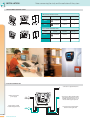
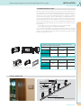
1
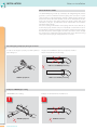
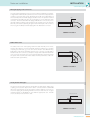
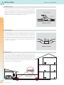
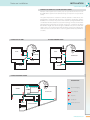
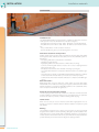
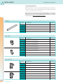
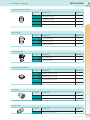
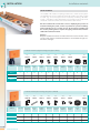
SINCE 1993
www.sistemair.com
Quick installation guide
Notes on installation
INSTALLATION
NOTES ON INSTALLATION
The SISTEM-AIR piping is made up of antistatic, self-extinguishing PVC, built to
guarantee a perfect combination between piping and connections. In particular, the piping is: Self-extinguishing, antistatic, calibrated, with thickness of
between 2.2 mm for Ø 50 mm diameter and 3 mm for Ø 63/80/100 mm diameter. All connections of the piping network are glued together with special
self-adhesive cold glue. Its particular technical characteristics ensure that the
glued parts stick perfectly.
The correct setting and installation of the piping network ensures that the system works properly and this is why it is undoubtedly considered the most important stage for obtaining optimum running of the centralised vacuum system.
We advise all operators to stick rigidly to the advice provided in order to simplify
the operations for compiling the piping network and ensure optimum running
of the system, thus keeping a steady performance over time.
Cut of the piping and proper joining of connectors
In order to cut the pipes properly, use ONLY cylindrical
pipe cutting tool.
The pipes should ALWAYS be placed correctly: they should always be inserted till it reaches the ledge.
RIGHT cut and WRONG positioning
PROPER equipment
RIGHT cut and RIGHT positioning
Examples of WRONG pipe cutting
UNSUITABLE tool for cutting.
!
Example of cut made with an unsuitable tool.
!
WRONG Equipment
1
www.sistemair.com
WRONG Installation
Notes on installation
INSTALLATION
central vacuum systems
Gluing the piping to the connectors
The stage of gluing the piping to the connectors is without a doubt the most delicate stage of the central vacuum system because if it is not carried out properly, there
could be a loss in flow of the system. Overtime, this would cause sedimentation of
the vacuumed product inside the piping located into chase. The operation is carried
out properly by spreading the glue only on the piping or on the male part of the
connector. This ensures that when the piping is fitted to the connector, any excess
glue will overflow creating an extra hold ring. If the operation were to be done the
other way round, that is, spreading the glue onto the female part of the connector,
the excess glue would drip inside the piping when it is fitted to the connector.
Glue
CORRECT Installation
Radius of the curve
The radius of the curve of the piping network located externally or into chase,
must be done with 45° connectors that will guarantee as little force as possible
of passing vacuumed air, e.g.: a 90° curve can be made in two different ways,
firstly with a male female and female female curve connector; secondly with a
female female curve connector, a small piece of pipe and another female female
curve connector. The fewer curve connectors installed in the system the greater
the speed of the vacuumed air and the better the final performance of the centralised vacuum system will be.
45°
45°
CORRECT Installation
Linear junction of the pipe
The junction of the piping must be made with the appropriate double stop
coupling connector; the stop found in all the connectors with a SISTEM-AIR
label is the element that ensures the piping combines with the connector. To
ensure the piping fits perfecting with the connectors and there are no gaps
inside the piping, it is ESSENTIAL to cut it with the appropriate tool. This will
ensure an exact, linear cut with no burr.
Perfect internal fit
CORRECT Installation
2
www.sistemair.com
Notes on installation
INSTALLATION
Direction of suction
For the branching of more inlet valve points, use the female female 45° derivation
connectors, or male female 45° derivation. This connector is used both for the derivation of a socket pipe line on the same floor and for the stable implementation of
upright pipes on several floors. It is essential that the derivation is always installed
correctly in relation to the system’s direction of suction (see figure). The incorrect
installation of the derivation will inevitably block the system.
Direction of suction
o the central
vacuum unit
CORRECT Installation
Special situations
During installation you may encounter obstacles that cannot be overcomed because the foundation is not properly levelled: this problem can be resolved with
a so called underground passage. The underground passage should be done
with a male female 45° curve connector, a female female 45° connector, a small
piece of pipe, another male female 45° elbow connector and another female
female 45° elbow connector. This operation should be carried out as few times
as possible on the same system, as it would produce a considerable strain on the
speed of the vacuumed air.
CORRECT Installation
Expansion joint
Under system conditions like those shown in the figure below, attention should focus on expansion of the ground: SISTEM-AIR resolves this problem by using special
expansion joints (see chapter on “Installation”) to be installed: one right at the outlet
of the piping in the first structure and a second one before the inlet of the second
structure. The piping located in the ground should be insulated in order to reduce
condensation inside the piping as much as possible, as this could create incrustation
if it were to come into contact with the dust.
Expansion joint
3
www.sistemair.com
Notes on installation
INSTALLATION
central vacuum systems
Standard mounting plate with elbow connector
Standard mounting plate with straight connector
The standard mounting plate with elbow connector,
only 7 cm thick, can be installed in any kind of wall. The
mounting plate is fitted with an elbow connector that
rotates at 360° in order to position itself to the connector, wherever it may be. IMPORTANT: the mounting plate should always be installed flat into the wall.
The standard mounting plate with straight connector
should be regarded as a suitable part for all those unusual
jobs (restoration, false walls, partitions etc.). IMPORTANT:
the mounting plate should always be installed flat into the
wall.
CORRECT Installation
CORRECT Installation
Fitting the mounting plate with elbow connector
Fitting the mounting plate with straight connector
Fitting the mounting plate with elbow connector
to the wall or outside requires maximum precision
so that when the inlet valve is fitted, the holding elements adhere perfectly. It is especially important the
mounting plate box is completely flat into the wall.
Fitting the mounting plate with straight connector to the
wall or outside requires maximum precision so that when
the inlet valve is fitted, the holding elements adhere perfectly. It is especially important the mounting plate box is
completely flat into the wall.
INCORRECT Installation
INCORRECT Installation
4
www.sistemair.com
Notes on installation
INSTALLATION
EXAMPLE OF BASE CONNECTIONS
Example of base connection to install the inlet valve.
ARTICLE
PRODUCT DESCRIPTION
1
1850.0
Ø 50 mm thick PVC pipe 2,2
2
4050.1
Ø 50 mm 45° F.F. PVC derivation
3
3050.0
Ø 50 mm 45° MF PVC elbow connector
4
1450.0
Standard mounting plate, straight connector with cover
5
9016.7
2x1 25 m pre-wired conduit
5
9016.0
2x1 50 m pre-wired conduit
5
9016.1
2x1 100 m pre-wired conduit
EXAMPLE OF CONNECTION TO INLET VALVES
Example of connection to inlet valves.
Rectangular mounting plate
on the wall
Clamps
SISTEM-AIR inlet valve
Decorative plaque (not provided)
5
www.sistemair.com
Notes on installation
INSTALLATION
central vacuum systems
EXAMPLE OF DOMESTIC SYSTEM ON THREE FLOORS
Example of sized system to be used by only one operator at the most on each
floor (NB: all the systems in the domestic range can only have one operator at
a time).
The system in question is created in a domestic structure on three floors. The
piping will be exclusively Ø 50 mm both as regards the upright pipe and the
distribution on each floor. The position of the vacuum openings should take into
consideration the fact that the hose used for cleaning is 7 metres: it is therefore
important when positioning the vacuum openings to consider the problems
that furniture might cause and not forget to add balconies, terraces and other
surface areas. The central vacuum units should be selected according to the
surface area to be cleaned, in order to ensure long life and the best performance
over time.
PLAN OF FIRST FLOOR
PLAN OF GROUND FLOOR
STUDY
ROOM
A
A
BATHROOM
LIVING ROOM
A
WC
CHANGING ROOM
BATHROOM
ROOM
A
A
A
ROOM
KITCHEN
PLAN OF BASEMENT FLOOR
DESCRIPTION
STOCK ROOM
GARAGE
SYSTEMS
Ø 50 mm PVC piping
A
Micro switch line
STOCK ROOM
A
A
Inlet valve
LAUNDRY
A
A
A
STOREROOM
Upright pipe
A
CENTRAL HEATING AREA
Central vacuum unit
GREENHOUSE
6
www.sistemair.com
Installation materials
INSTALLATION
INSTALLATION
Installation area
The SISTEM-AIR installation material in PVC is suitable for all kinds of central vacuum systems and can be divided into four product categories:
- Grey Ø 50 mm, 2.2 mm thick . Ø 63 - Ø 80 - Ø 100mm, 3.0 mm thick piping
- Grey Ø 50 mm, 2.2 mm thick. Ø 63 - Ø 80 - Ø 100mm, 3.0 mm thick connectors
- Grey conduit with 2, 1 mm2 conductors inserted.
- Special self-adhesive glue to join the piping to the connectors.
Particular characteristics of the product
Quality, sturdy system products that meet with the strictest safety and quality
homologations and certifications that satisfy even the most difficult system requirements.
- PVC piping with static load reduced to a minimum.
- UNI approved grey piping.
- Rigid piping with connectors that have a wide radius of curving.
- Connectors with angular reference notches for a correct coupling between
piping and connectors.
- PVC plastic material that can be welded cold using a special glue.
- Fire resistant PVC material in compliance with M1 resistance cat. and IEC regulations.
- Grey Ø 16 mm pre-wired conduit with CE, IMQ labelling, suitable for ordinary
and unusual environments where you need to use non toxic products.
- Certification from the Italian Institute of Plastics in compliance with UNI regulations.
Main charcteristics
Rigid piping with connectors that have a wide radius of curving. PVC plastic
material that can be welded cold using a special glue. Certification of the Italian
Institute of Plastics in compliance with UNI regulations. Fire resistant PVC material in compliance with CEI 23-29 regulations.
Criteria for choosing the piping network
The PVC piping and connectors are suitable for all kinds of centralised vacuum
system installations. Aluminium piping can be used where there are particular
mechanical resistance problems, or, when installing visible piping.
Technical note
When it is necessary to cross an external section with a rigid pipeline it is opportune to prepare a suitable isolation with the addition of expansion joints
(art. 5050.0).
Warning
The installation material, such as pipes and connectors, has been specifically
designed and created for central vacuuming. Using the specific installation material allows you to create systems with a maximum guarantee on performance
and the assurance that it will not block. Any other material would jeopardise the
system’s warranty and could create blocking in the piping network.
7
www.sistemair.com
Installation materials
INSTALLATION
central vacuum systems
SISTEM CASE
Sistem Case is a new case to build in Sistem Air central units, especially developed
to save space and to aesthetically integrate the vacuum unit in the wall. It is
realized in strong zinc-coated steel and thanks to its telescopic structure it fits
any MINI and MEDIA Sistem Air vacuum unit. With a single code you can match
different installation needs. The cover, made of plastic material in aluminium
colour, has a futuristic and at the same time simple design. It is available in two
different versions, depending on the kind of central unit to be installed. Sistem
Case is only 23 cm deep and allows the connection to the piping system from
the left or from the right.
BUILD IN CASE FOR TA/TE MINI AND MEDIA UNITS
ARTICLE
7100.0
Packaging (pieces)
PRODUCT DESCRIPTION
Universal case to build in units TA/TE MINI e MEDIA
1
CASE COVER
ARTICLE
7100.1
Case cover for units MINI
1
7100.2
Case cover for units MEDIA
1
DIMENSIONS
Solution for the installation
of units TE/TE Media
1000
Solution for the installation
of units TA/TE Mini
850
EXAMPLE OF POSITIONING
Packaging (pieces)
PRODUCT DESCRIPTION
55
0
23
0
55
0
23
0
8
www.sistemair.com
Installation materials
INSTALLATION
INSTALLATION MATERIAL
Rigid PVC piping and connectors especially designed for central vacuum systems with a view to create a perfect fit between the piping and connectors;
only 45° connectors are provided to allow for the best air flow possible without
creating the possibility of the system blocking.
NB: It is extremely important that the rigid PVC piping is cut using the
appropriate tool (pipe cutter) and that the hold between the joints is
guaranteed by using the special SISTEM-AIR glue in abundance, spreading
it on the male and never on the female connector.
PVC PIPING
ARTICLE
DESCRIPTION
PACKING m
1850.0
Ø 50 2.2 mm thick PVC PIPE (2 m bars)
20
1863.0
Ø 63 3 mm thick PVC PIPE (2 m bars)
25
1880.0
Ø 80 3 mm thick PVC PIPE (2 m bars)
10
1810.0
Ø 100 3 mm thick PVC PIPE (2 m bars)
10
ARTICLE
DESCRIPTION
3050.0
Ø 50 45° male / female PVC elbow
60
3063.0
Ø 63 45° male / female PVC elbow
30
3080.0
Ø 80 45° male / female PVC elbow
1
3010.0
Ø 100 45° male / female PVC elbow
1
3050.1
Ø 50 45° female / female PVC elbow
60
3063.1
Ø 63 45° female / female PVC elbow
30
3080.1
Ø 80 45° female / female PVC elbow
1
3010.1
Ø 100 45° female / female PVC elbow
1
ARTICLE
DESCRIPTION
4050.0
Ø 50 45° male / female / female PVC DERIVATION
20
4063.0
Ø 63 45° male / female / female PVC DERIVATION
15
4080.0
Ø 80 45° male / female / female PVC DERIVATION
1
4010.0
Ø 100 45° male / female / female PVC DERIVATION
1
4050.1
Ø 50 45° female / female / female PVC DERIVATION
20
4063.1
Ø 63 45° female / female / female PVC DERIVATION
15
4080.1
Ø 80 45° female / female / female PVC DERIVATION
1
4010.1
Ø 100 45° female / female / female PVC DERIVATION
1
PVC 45° ELBOW
PACKING pcs.
PVC 45° DERIVATION
9
www.sistemair.com
PACKING pcs.
Installation materials
INSTALLATION
central vacuum systems
PVC COUPLING FOR LINEAR JUNCTIONS
ARTICLE
DESCRIPTION
PACKING pcs.
1150.1
ø 50 PVC stop coupling
100
1163.1
ø 63 PVC stop coupling
40
1180.1
ø 80 PVC stop coupling
1
1110.1
ø 100 PVC stop coupling
1
ARTICLE
DESCRIPTION
6063.3
ø 50/63 hose adaptor
1
8080.3
ø 63/80 hose adaptor
1
1010.3
ø 80/100 hose adaptor
1
ARTICLE
DESCRIPTION
5050.0
ø 50 expansion joint
1
5050.2
ø 63 expansion joint
1
ARTICLE
DESCRIPTION
5050.1
ø 50 PVC inspection screw cap
1
6063.1
ø 63 PVC inspection screw cap
1
8080.1
ø 80 PVC inspection screw cap
1
1010.1
ø 100 PVC inspection screw cap
1
ARTICLE
DESCRIPTION
5050.4
ø 50 exhaust vent
1
5063.4
ø 63 exhaust vent
1
ARTICLE
DESCRIPTION
110001
standard ø 50 / 2” PVC silencer
PVC PIPE ADAPTER
PACKING pcs.
PVC EXPANSION JOINTS
PACKING pcs.
PVC SCREW CAPS FOR INSPECTING
PACKING pcs.
AIR VENT GRATE
PACKING pcs.
AIR VENT SILENCER
PACKING pcs.
1
10
www.sistemair.com
Installation materials
INSTALLATION
SPECIAL GLUE FOR PVC PIPES
PRE-WIRED CONDUIT 2 X 1 MM
ARTICLE
DESCRIPTION
PACKING pcs.
9225.1
250 g of special glue with brush
5
9225.2
500 g of special glue with brush
5
9500.0
500 g of special glue without brush
4
ARTICLE
DESCRIPTION
9016.7
2x1 mm2 (25 m) pre-wired conduit
1
9016.0
2x1 mm2 (50 m) pre-wired conduit
1
9016.1
2x1 mm2 (100 m) pre-wired conduit
1
ARTICLE
DESCRIPTION
2050.0
ø 50 ball valve for manual division
1
2050.1
ø 63 ball valve for manual division
1
2050.2
ø 80 ball valve for manual division
1
2050.3
ø 100 ball valve for manual division
1
ARTICLE
DESCRIPTION
1150.3
ø 50 fire stop coupling
1
1163.2
ø 63 fire stop coupling
1
1180.2
ø 80 fire stop coupling
1
ARTICLE
DESCRIPTION
5050.5
Screw cap for testing domestic system installations
ARTICLE
DESCRIPTION
1850.0A
Alluminium pipe alloy 6060; Ø 50 - 2,2 mm Thick (3 m Bars)
9
1863.0A
Alluminium pipe alloy 6060; Ø 63 - 2,2 mm Thick (3 m Bars)
9
2
PACKING pcs.
BALL VALVE FOR MANUAL DIVISION
PACKING pcs.
Fire stop coupling
PACKING pcs.
Screw cap for testing installation
PACKING pcs.
5
ALLUMINIUM PIPE
11
www.sistemair.com
PACKING pcs.
Installation materials
INSTALLATION
central vacuum systems
ZINC-COATED STEEL INSTALLATION MATERIAL
Rigid steel pipes and connections, built
to guarantee endurance and electric
transmission in all the contexts where
these characteristics are essential for the
correct installation.
STEEL PIPE
ARTICLE
DESCRIPTION
PACKING pcs.
1850.0F
Steel pipe Ø 50 (2 m bars)
1
1863.0F
Steel pipe Ø 60 (2 m bars)
1
ARTICLE
DESCRIPTION
3050.1F
Elbow pipe 45° Male /Male Ø 50
3
3063.1F
Elbow pipe 45° Male /Male Ø 60
3
ARTICLE
DESCRIPTION
3050.0F
Elbow pipe 90° Male /Male Ø 50
5
3063.0F
Elbow pipe 90° Male /Male Ø 60
5
ARTICLE
DESCRIPTION
4050.0F
Derivation pipe 45° Male /Male / Male Ø 50
2
4063.0F
Derivation pipe 45° Male /Male / Male Ø 60
2
ARTICLE
DESCRIPTION
1150.1F
Junction group steel pipe Ø 50
5
1163.1F
Junction group steel pipe Ø 60
5
ARTICLE
DESCRIPTION
6050.0F
Steel adapter Ø 50/60
45° ELBOW PIPE
PACKING pcs.
90° ELBOW PIPE
PACKING pcs.
45° DERIVATION PIPE
PACKING pcs.
JUNCTION GROUPS
PACKING pcs.
STEEL ADAPTER
PACKING pcs.
1
12
www.sistemair.com
Installation materials
INSTALLATION
INSTALLATION KIT
The installation kit includes everything needed to fit a central vacuum system.
The installation kits can be combined to obtain the number of sockets you wish
to install. (e.g.: an 8 socket system can be created by combining 1 kit with 3
sockets + 1 kit with 5 sockets; alternatively, 2 4 socket kits can be used). The list
of material contained in the kit can be checked in the tables below.
N.B. The installation kit is made with a view to simplifying the purchase of
material for fitting the system, as much as possible. For systems in buildings
with standard layout, it is possible to have all the material available with
the certainty of being able to complete the piping network without further
additional installation material.
Warning
Only the installation material is included in the kit because the inlet valves
are part of the system and should therefore be selected from the right section of the catalogue.
Installation kit with rectangular mounting plates (parts no.1450.0)
Art.
1450.0
Art.
1850.0
Art.
3050.0
Art.
3050.1
Art.
4050.1
Art.
1150.1
Art.
5050.4
Art.
9225.1
Coupling
Pieces
Vent grate
Pieces
Conduit
(m)
Special glue
Pieces
TO
AL
ARTICLE
No. of sockets
EC mounting
plate Pieces
PVC pipe
(m)
MF elbow
Pieces
FF elbow Pieces FF derivation
Pieces
7030.3
3
3
20
9
12
3
9
1
25
1
7030.4
4
4
28
12
16
4
12
1
37,5
1
7030.5
5
5
36
15
20
5
15
1
50
1
Art.
1150.1
Art.
5050.4
Coupling
Pieces
Vent grate
Pieces
Conduit
(m)
Special glue
Pieces
Installation kit with square mounting plates (parts no.1450.4B)
Art.
1450.4B
Art.
1850.0
Art.
3050.0
Art.
3050.1
Art.
4050.1
ARTICLE
No. of sockets
EC mounting
plate Pieces
PVC pipe
(m)
MF elbow
Pieces
7030.3E
3
3
20
9
12
3
9
1
25
1
7030.4E
4
4
28
12
16
4
12
1
37,5
1
7030.5E
5
5
36
15
20
5
15
1
50
1
13
www.sistemair.com
FF elbow Pieces FF derivation
Pieces
Art.
9225.1
Installation materials
INSTALLATION
central vacuum systems
TECHNICAL CHARACTERISTICS OF THE INSTALLATION MATERIAL
PIPING
Ø 50x2.2 mm, Ø 63x3 mm, Ø 80 x3 mm, Ø 100x3 mm
PVC piping (non plastic polyvinyl chloride, PVC-U) for air suction.
Self-extinguishing piping, cat. 1 according to material classification
in the D.M 26.06.1984 (Ministerial Degree) based on ISO 1182, UNI
8457 test methods.
Grey
Compliance with legislation:
Ø 50 pipes – Specification based on former UNI 7443:1985 + F.A.
178:1987
P.I.I.P. certification issued by the Italian Institute of Plastics.
Ø 63-80-100 pipes - UNI EN 1329:2000
P.I.I.P. certification issued by the Italian Institute of Plastics.
Applied compliance label: Piip/c 261.
The SISTEM-AIR rigid piping with circular section is for use on centralised vacuum systems and for discharge that is not under pressure or
compressed ventilation.
Ideal for glued joints.
CONNECTORS
PVC connectors for air suction.
The connectors have a calibrated coupling diameter to obtain the
best coupling with the piping.
Available in numerous forms and connections, in Ø 50 , Ø 63 , Ø 80, Ø
100 diameters as well as the numerous accessories.
Colour: grey.
Self-extinguishing.
Fire resistance level: behavioural category according to RSN-M1 legislation (superior standard quality in the field of plastic fire resistance).
STEEL PIPES AND CONNECTORS
Pipes’ thickness: Ø 50x2 mm, Ø 60x1,8 mm.
Material: P02
Caracteristics: welded and seamed without internal welding, with
deep drawing.
ALUMINIUM PIPES
Pipes’ thickness: Ø 50x1,5 mm, Ø 63x1,5 mm.
Material: alluminium UNI EN 573 - 3
EN AW - 6060 (ALMGSI) heat treated and aged.
Chemical characteristics: UNI EN 573 - 3
Mechanical characteristics: UNI EN 755 - 2
PRE-WIRED CONDUIT
Pre-wired, protective, folding insulating conduit.
Grey with Ø 16 mm diameter.
CE, IMQ labelling.
IMQ certification.
Complies with the following regulations:
-EN 50086-1:1993
-EN 50086-2-2:1995 +A11:1998
Products conform to the essential requirements found in the B.T.
73/23/CEE directive and later changes.
Pipe with C1 base classification. 3422, corrugated, DOES NOT propagate flames.
Further C1 classification. 32-0-010.
Product has no halogen as required by law:
IEC EN 50267-2-1:1999 and IEC EN 50267-2-2:1999.
This kind of conduit is suitable for all those places requiring non toxic
characteristics and non emission of fumes or toxic gases.
Reference document:
IEC EN 50267-1:1999 -Cat. IEC 20-37/2-0- F. 5325
IEC EN 50267-2-1:1999-Cat. IEC 20-37/2-1- F. 5326
The same as IEC 60754-1
IEC EN 50267-2-2:1999-Cat. IEC 20-37/2-2- F. 5327
The same as IEC 60754-2.
Suitable in cases where particular mechanical resistance is needed.
Crush resistance (pipe): Cat. 3 average (greater than 750 N on 5 cm
at +20°C)
Blow resistance (pipe): Cat. 3 average (2 joules at -5°C)
Minimum working temperature (pipe): Cat. 2 (-5°C)
Maximum working temperature (pipe): Cat. 1 (+60°C)
For the cables:
The conduction wires are IMQ certified, red and No7VK type, do not
propagate fire, with 1 mm2 section
Legislation:
IEC 20-20, 20-22, 20-37
IEC-UNEL 35752
CENELEC H D 21
FIRE FIGHTING COUPLINGS
To be applied everywhere that fire prevention legislation is in effect.
Fire resistance cat.: REI 180 certified (180 min).
The fire fighting couplings are used to seal the crossings of engineering resin pipes (PVC, PE, PP,..) in fire prevention compartments.
At a temperature of approx. 150°C, the internal intumescent material
starts to expand thus increasing its own volume by about 10 times,
developing a considerable pressure, enough to activate the fire resistance closure system that keeps in burning gases.
Read the safety instructions before use.
To use them, the fire stop couplings must be used in compliance with
fire resistance certificates both in number and orientation as well as fixing system.
GLUE
Certified PVC based glue dissolved in solvent.
Basic ingredients: PVC resins.
Special ingredients: organic solvents.
Solder the glued junction.
Gluing is equally resistant to chemical agents and has the same mechanical properties as hard PVC.
Its controlled viscosity means it can easily be applied without gluing.
Ideal for longitudinal junctions on hard PVC pipes and the assembling of PVC
pipes and connectors.
14
www.sistemair.com
Notes concerning the study and the realisation of the system
INSTALLATION
TABLE REMOTE CONTROL PANEL
TABLE REMOTE CONTROL OANEL
ARTICLE
COLOUR
MATERIAL
PACKING (pcs)
4200.2
ALUMINIUM
PLASTIC
1
4200.3
ANTHRACITE
PLASTIC
1
MATERIAL
PACKING (pcs)
PLASTIC
1
197
8
RE
SE
194
109
WALL REMOTE CONTROL PANEL
162
ARTICLE
8
4200.0
RE
SE
172
COLOUR
ANTHRACITE
70
ELECTRIC CONNECTION
Connection to system’s Micro Line
Remote control panel
power supply
PROG
PIN
ON
POWER
Power supply to central
vacuum unit (optional use)
15
www.sistemair.com
Connection of outlet cable for maintenance warning signal (“N.O.” contact
normally open, max 12 Volt – 0.10 A)
N.B.: Use of this signal is optional
Connection to the central vacuum
unit’s micro line signal cable
Notes concerning the study and the realisation of the system
INSTALLATION
central vacuum systems
ELECTRONIC CONTROL SYSTEMS
Remote control electronic systems can be used to control the maintenance of
the central unit on Domestic, Professional and Industrial series. The remote control systems for the Tecno series, is built with particular emphasis in design. It
allows you to check out the programmed maintenance required, so that the
central unit works perfectly. The ease with which it is installed allows you to
use it on all existing systems in the central vacuum sector, and the pre-set programming allows you to use it immediately. In order to personalise the maintenance cycles, it is possible to intervene on the programming modality foreseen,
following the instructions found in the user’s manual. Tecno Control comes in
three versions:
- “Control-Table”, for use in the reception of a hotel or public building
- “Control-Wall” , for professional use with wall installation
The connection and installation are extremely easy as this is done by connecting
up to the main electric power network and any micro line point of the vacuum
system. You can programme the dust container emptying cycles, filter cleaning
and motor maintenance cycles.
STANDARD REMOTE CONTROL WALL PANEL (COMBINABLE WITH ALL
CENTRAL UNIT MODELS ON THE MARKET)
COLOUR
MATERIAL
PACKING (pcs)
4200.6
WHITE AND BLACK
PLASTIC
1
65
ARTICLE
118
36
WALL REMOTE CONTROL PANEL WITH BOX AND PLAQUE
COLOUR
MATERIAL
PACKING (pcs)
4200.7
White
KUNSTSTOFF
1
74
ARTICLE
2
53
11
Supply: Wall box, Model 503 – Vimar IDEA 3 plaque Bianca modules
ELECTRIC CONNECTION
V~
220/240
N
L
Remote control panel
12 V dc MICRO RANGE
Inlet valves
Vacuum system piping
N.B.: Possible connection in any micro line point.
16
www.sistemair.com
perfect fit
of all components
SINCE 1993
27020 Gravellona Lomellina (PV) ITALIA - Via Cilavegna, 53 - GPS: N: 45° 19’ 28”; E: 8° 45’ 32”
Tel. + 39 0381 650082 - Fax +39 0381 650120 - [email protected] - www.sistemair.com