1
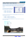
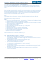
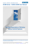
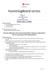
AccessZone ® - GC1000 Series – GC1001-GC1004 User Manual
GC1000 Series – GC1001-GC1004 User Manual
The New Generation of Wireless
Access Control Systems
User Manual for GC1001-GC1004 with firmware Ver. 1.72 and above
For modules with serial numbers from 120000
All information is subject to change without notice. All other products and brand names are registered trademarks of their respective companies
2010-01-21 US 1.03
Copyright © 2005-2010 All rights reserved MVC-Data ApS Skalhuse 5 9240 Nibe Denmark Web www.mvc-data.com E-mail [email protected] Phone +45 25 12 84 02
1/33
AccessZone ® - GC1000 Series – GC1001-GC1004 User Manual
AccessZone® System - A Key to a Safer Future
Congratulations on choosing an AccessZone® Access Control System. It is a flexible and easy to use
system for controlling access to doors and gates to private homes, shops and small and middle size
companies. It enables quick configuration with a few simple commands entered on a standard
mobile phone with Bluetooth without installing any software. No license or subscription is
required.
This manual covers the easy configuration of
the AccessZone® GC1000 series of stand-alone
Access Control Systems via a mobile phone:
GC1001 – 2 admin. and 5 users
GC1002 – 2 admin. and 10 users
GC1003 – 2 admin. and 20 users
GC1004 – 2 admin. and 50 users
AccessZone® GC1000 Form factor 200 x 120 x 60 mm
The system is also available with Bluetooth, RS232/RS422/RS485 and LAN interface to the PC
based PcManagement system as:
GC2000 – up to 2000 users, 512 logs, I/O 3/3
GC3000 – up to 2000 users, 512 logs, I/O 4/4
GC4000 – up to 2000 users, 512 logs, I/O up to 8/8
Please see the GC1000/GC2000/GC3000/GC4000 series Installation Manual for instructions on
how to install the system.
Get easy and seamless accesses to the secured areas with your mobile phone
working as a secure access key from a distance of 0.1 up to 10 meters.
All information is subject to change without notice. All other products and brand names are registered trademarks of their respective companies
2010-01-21 US 1.03
Copyright © 2005-2010 All rights reserved MVC-Data ApS Skalhuse 5 9240 Nibe Denmark Web www.mvc-data.com E-mail [email protected] Phone +45 25 12 84 02
2/33
AccessZone ® - GC1000 Series – GC1001-GC1004 User Manual
Table of Contents
1 Disclaimer .........................................................................................................................................5
2 Introduction.......................................................................................................................................6
3 Security Precautions..........................................................................................................................7
4 System Overview...............................................................................................................................8
5 I/O Description..................................................................................................................................8
5.1 Inputs..........................................................................................................................................8
5.2 Outputs.......................................................................................................................................8
6 LED Status..........................................................................................................................................8
7 How to Configure the System............................................................................................................9
7.1 Commands via Mobile................................................................................................................9
7.2 How to enter Configuration Mode...........................................................................................10
7.3 How to enter System Commands – Configuration Mode........................................................11
7.3.1 If the system doesn’t respond to a command:.................................................................11
7.4 How to Add or Delete Users – Normal Operation...................................................................12
7.4.1 If the system doesn’t respond to a command:.................................................................12
8 System Commands..........................................................................................................................13
8.1 Change 8 digit Master PIN Code Command.............................................................................13
8.2 Add new User Command.........................................................................................................14
8.3 Delete User Command.............................................................................................................16
8.4 Change System Configuration Command 1.............................................................................17
8.5 Change System Configuration Command 2 – Advanced settings............................................19
9 Request Exit – REX Push Button .....................................................................................................21
10 Alarm Arming and Disarming........................................................................................................21
10.1 Disarming the Alarm...............................................................................................................21
10.2 Arming the Alarm...................................................................................................................21
10.3 Timing Diagram of the outputs – Normal Access and Arming the Alarm..............................22
10.4 Timing Diagram of the Outputs – Normal Access and Reject Arming of the Alarm.............. 22
11 Virtual Keypad...............................................................................................................................23
11.1 Virtual Keypad only Mode......................................................................................................23
11.2 Virtual Keypad Mixed Mode...................................................................................................23
12 User Access Key Setup...................................................................................................................24
12.1 Mobile Phone as Key..............................................................................................................24
12.2 GPS Key as Key........................................................................................................................25
13 Door/Gate Output Type................................................................................................................26
13.1 Pulse.......................................................................................................................................26
13.2 Level........................................................................................................................................26
13.3 Latched (toggle)......................................................................................................................26
14 Access Detection Range................................................................................................................27
14.1 Detection Range Command Examples...................................................................................27
14.2 Detection range is to short.....................................................................................................28
14.3 Detection range is too long....................................................................................................28
15 Default Factory System Settings....................................................................................................29
15.1 Restore Factory Default System Settings...............................................................................29
16 Appendix A – User Log Template..................................................................................................30
17 Appendix B – System Master PIN Code Log Template..................................................................30
18 Appendix C – System Configuration Log Template.......................................................................30
19 Appendix B – Quick Guide:............................................................................................................31
19.1 Mobile Phone used for Adding and Deleting Users – Normal Operation:.............................31
All information is subject to change without notice. All other products and brand names are registered trademarks of their respective companies
2010-01-21 US 1.03
Copyright © 2005-2010 All rights reserved MVC-Data ApS Skalhuse 5 9240 Nibe Denmark Web www.mvc-data.com E-mail [email protected] Phone +45 25 12 84 02
3/33
AccessZone ® - GC1000 Series – GC1001-GC1004 User Manual
19.2 Mobile Phone used for System Commands - System Configuration Mode:..........................32
19.3 Mobile Phone as Access Key: ................................................................................................33
All information is subject to change without notice. All other products and brand names are registered trademarks of their respective companies
2010-01-21 US 1.03
Copyright © 2005-2010 All rights reserved MVC-Data ApS Skalhuse 5 9240 Nibe Denmark Web www.mvc-data.com E-mail [email protected] Phone +45 25 12 84 02
4/33
AccessZone ® - GC1000 Series – GC1001-GC1004 User Manual
1
Disclaimer
All rights reserved.
MVC-Data ApS assumes no responsibility for any errors in this manual.
MVC-Data ApS is constantly working to improve its products and offer new features in
collaboration with customers and partners. Therefore, MVC-Data ApS reserves the right to change
the hardware, software and / or specifications without notice and shall have no obligation to
update the information contained in this manual.
MVC-Data ApS's products are not authorized for use as system-critical components in life
supporting devices or systems.
AccessZone® is a registered trademark of MVC-Data ApS. The Bluetooth trademark is owned by
the Bluetooth SIG. All other trademarks are owned by their respective owners.
The displayed screens may differ and depends on the mobile phone used for configuration.
Copyright © 2005-2010 MVC-Data ApS
All information is subject to change without notice. All other products and brand names are registered trademarks of their respective companies
2010-01-21 US 1.03
Copyright © 2005-2010 All rights reserved MVC-Data ApS Skalhuse 5 9240 Nibe Denmark Web www.mvc-data.com E-mail [email protected] Phone +45 25 12 84 02
5/33
AccessZone ® - GC1000 Series – GC1001-GC1004 User Manual
2
Introduction
The AccessZone GC1000 series GC1001-GC1004 are stand-alone access control systems. They are
well suited for use in private homes, shops and minor companies.
They are unique wireless access control systems built on Bluetooth wireless technology – a
wireless technology that operates in the license free ISM band at 2.4 GHz.
The systems only allow access to users who can be identified by their unique Key ID and optional a
4 digit PIN code for increased security. The used mobile phones or other Bluetooth devices must
be set to “visible” to allow them to be discovered by the system.
The GC1000 series eliminates the need for mechanical readers and keyboards outside the secured
area. This removes the risk for property damage and breakdown due to harsh environmental
conditions and heavy use.
Please refer to the GC1000 Firmware Release Note for the latest changes.
Firmware version 1.72 introduces more users!
The 2 privileged users (administrators) are now added as additional users. I.e. all system
has been updated with 2 more users. I.e. GC1001 has now 7 (2+5), GC1002 12 (2+10),
GC1003 22 (2+20) and GC1004 52 (2+50) users.
All information is subject to change without notice. All other products and brand names are registered trademarks of their respective companies
2010-01-21 US 1.03
Copyright © 2005-2010 All rights reserved MVC-Data ApS Skalhuse 5 9240 Nibe Denmark Web www.mvc-data.com E-mail [email protected] Phone +45 25 12 84 02
6/33
AccessZone ® - GC1000 Series – GC1001-GC1004 User Manual
3
Security Precautions
Several security precautions have been implemented in the system to make it safe to use.
The system will only accept system configuration commands in a special configuration mode (refer
to section 7.2 How to enter Configuration Mode).
All system configuration commands are entered by temporarily changing the mobile phones
friendly name 1) and must be followed by a unique 8 digit master PIN code. The master PIN code
should only be known to a limited number of people (system administrators).
The 8 digit master PIN code should be changed and is unique for each GC1001-GC1004 system. It
can be entered from any Bluetooth enabled mobile phone. Please change this PIN code before
continuing.
Two privileged users (administrators) can add and delete users at any time. Refer to section 7.4
How to Add or Delete Users – Normal Operation.
1)
Caution!
The Bluetooth friendly name feature is used for commands and can be read from another
Bluetooth device from the distance (typically up to 10 meters).
Therefore it is highly recommended to immediately change the Bluetooth friendly name again or
make the mobile phone invisibly to avoid that unauthorized people read the commands
containing vital user information.
All information is subject to change without notice. All other products and brand names are registered trademarks of their respective companies
2010-01-21 US 1.03
Copyright © 2005-2010 All rights reserved MVC-Data ApS Skalhuse 5 9240 Nibe Denmark Web www.mvc-data.com E-mail [email protected] Phone +45 25 12 84 02
7/33
AccessZone ® - GC1000 Series – GC1001-GC1004 User Manual
4
System Overview
This section presents a system overview with an I/O description:
Input 1 & 3
Block Operation
(Prevents any door/
Gate activation)
Input 2 / Key ‘1’
REX Button/
Alarm arming/
Alarms reject arming
5
Output 1
(Pulse or Level/ latched)
Door lock/Gate control
Output 2
(Level/latched)
Alarm Arm and Disarm/
Light Control Switch
Output 3
(Level/latched)
Door lock/Gate status signal
I/O Description
GC1000 series have 3 outputs and 3 inputs.
The active levels (high ‘1’/low ‘0’), when an action is performed, can be configured (inverted).
Please refer to section 8.5 Change System Configuration Command 2 – Advanced settings for more
details.
5.1
Inputs
Block Operation for preventing any door or gate activation on input 1 and 3
REX Button for exit and Alarm arming and disarming on input 2 and front key ‘1’
5.2 Outputs
Relay type (1 A):
Door lock/Gate Control on Output 1
Door lock/Gate Control status on Output 2
Alarm Arm and Disarm/Light Control Switch on Output 3
Please see the GC1000/GC2000/GC3000/GC4000 series Installation Manual for instructions on
how to install the system.
6
LED Status
The GC1000 series has 6 LEDs for system indications.
Please refer the GC1000/GC2000/GC3000/GC4000 series Installation Manual for a LED description.
All information is subject to change without notice. All other products and brand names are registered trademarks of their respective companies
2010-01-21 US 1.03
Copyright © 2005-2010 All rights reserved MVC-Data ApS Skalhuse 5 9240 Nibe Denmark Web www.mvc-data.com E-mail [email protected] Phone +45 25 12 84 02
8/33
AccessZone ® - GC1000 Series – GC1001-GC1004 User Manual
7
How to Configure the System
This section describes how to enter system commands and how to enable the system for
configuration. Section 8 System Commands describes the different commands in details.
7.1 Commands via Mobile
System configuration (adding/deleting users and changing system settings) can be done from any
Bluetooth enabled mobile phone.
Note!
It is not necessary to install any software on the mobile phone or use any PC tool.
The mobile phone used must support at least 20 characters as “Friendly Name” (also called
"Phone Name”). This is the name revealed for other Bluetooth devices.
A system command (e.g. "01,0022b4b62918,1234") is entered by temporarily changing the
mobiles Bluetooth “Friendly Name”. Refer to section 8 System Commands.
Please refer to the User Manual for a specific mobile phone type for how to change the Bluetooth
friendly name.
Caution!
The Bluetooth specification states a maximum length of 248 characters as Friendly Name.
However, most mobile phones have limited the space allowed for Friendly Name. A minimum of
20 characters must be supported by the used mobile phone.
All commands must be followed by an 8 digit master PIN code for safe use. The system gives 3
short beeps to indicate that a valid command has been found and the master PIN code is required.
The user will automatically be prompted when to enter the master PIN code.
Note!
This is not the normal 4 digit user access PIN code.
Please note when entering the commands:
All command parameters (enclosed by <>) must be separated by a comma ','
No spaces between values are allowed
Have the exact length as specified. I.e. no additional characters in the end
A ‘-‘ indicates an integer range 1,2,3…
All information is subject to change without notice. All other products and brand names are registered trademarks of their respective companies
2010-01-21 US 1.03
Copyright © 2005-2010 All rights reserved MVC-Data ApS Skalhuse 5 9240 Nibe Denmark Web www.mvc-data.com E-mail [email protected] Phone +45 25 12 84 02
9/33
AccessZone ® - GC1000 Series – GC1001-GC1004 User Manual
7.2 How to enter Configuration Mode
The system must be set into configuration mode before it will accept the system commands.
However, it is possible for two privileged users (administrators) to use the Add new User and
Delete User commands in normal mode (Refer to section 7.4 How to Add or Delete Users – Normal
Operation).
Follow these steps to enter configuration mode:
Steps:
1) Power off the module
2) Press and held down the REX (Request Exit) push button (IN2)
3) Power on the module again
4) The REX push button can be released after the short beep
The system is now in configuration mode for 10 minutes and will flash with the Blue LED. Refer to
section 7.3 How to enter System Commands – Configuration Mode for how to enter system
commands.
The system coverage range will be limited to approximately 20 cm in the configuration period to
prevent that unauthorized people can tamper with the system.
The configuration period is restarted every time a valid command has been executed.
Configuration mode is automatically terminated after 10 minutes without any valid commands by
sending 2 short beeps or by power cycling the device to startup in normal operation.
Note!
The system will not scan for (detect) users in configuration mode. I.e. no access is possible
All information is subject to change without notice. All other products and brand names are registered trademarks of their respective companies
2010-01-21 US 1.03
Copyright © 2005-2010 All rights reserved MVC-Data ApS Skalhuse 5 9240 Nibe Denmark Web www.mvc-data.com E-mail [email protected] Phone +45 25 12 84 02
10/33
AccessZone ® - GC1000 Series – GC1001-GC1004 User Manual
7.3 How to enter System Commands – Configuration Mode
The system commands (adding/deleting users and changing system settings) can be executed
from any Bluetooth enabled mobile phone by temporarily changing the mobile phones friendly
name.
After entering a command and the master PIN code the system gives a short beep to indicate that
the command has been accepted and executed and restarts the 10 minute configuration period.
The next command can be entered, or wait for the termination of the configuration period or
power cycle the device to startup in normal operation.
Note!
3 short beeps indicate when to use the master PIN code instead of normal access PIN code.
Follow these steps to execute commands:
Steps:
1) Set system into configuration mode. Refer to section 7.2 How to enter Configuration Mode
2) Enable Bluetooth on mobile phone and set it to hidden
3) Enter the required system command on the mobile phone and click save. Refer to section8
System Commands for available commands
4) Set the mobile phone to visible
5) Place mobile phone within the detection range of the system
6) Wait for 3 short beeps
7) Enter Master PIN code (e.g. 12345678) when prompt
8) Wait for beep for successful execution of the command
9) Set the mobile phone to invisible/hidden
10) Erase command from mobile phone
If more commands must be executed repeat step 2) – 9)
7.3.1 If the system doesn’t respond to a command:
System is not in configuration mode any more (10 minutes time out)
- Check Blue LED - flashing? Else re-enter configuration mode. Refer to section 7.2 How to
enter Configuration Mode
The administrator is outside the allowed configuration range
- Administrator must get closer to the system
The command has already been executed
- Try change one of the parameters or try another command
The command is not valid
- Wrong number of parameters, wrong parameter values and/or wrong command length
(e.g. spaces at the end)
The system time out waiting reading the command or connection to mobile failed
- Wait for next detection
All information is subject to change without notice. All other products and brand names are registered trademarks of their respective companies
2010-01-21 US 1.03
Copyright © 2005-2010 All rights reserved MVC-Data ApS Skalhuse 5 9240 Nibe Denmark Web www.mvc-data.com E-mail [email protected] Phone +45 25 12 84 02
11/33
AccessZone ® - GC1000 Series – GC1001-GC1004 User Manual
7.4 How to Add or Delete Users – Normal Operation
Privileged users (administrators) are stored on storage position 01 or 02. These two privileged
users (administrators) are allowed to add and delete users from normal operation mode. I.e. it is
not necessary to enter configuration mode first.
The user (administrator) must first enter the normal access 4 digit PIN code as normal and if a
valid and new Add new User or Delete User command is found the 8 digit master PIN code.
A short beep indicates that the command has been successfully executed as in normal
configuration mode.
TIP!
Make sure that the mobile phone used is stored on position 01 or 02 before continuing.
Follow these steps to add or delete a user:
Steps:
1) Enter the required Add new User or Delete User command on the mobile phone and click
save (refer to section 8.2 Add new User Command and 8.3 Delete User Command)
2) Set the mobile phone to visible
3) Place mobile phone within the detection range of the system
4) Enter normal access PIN (e.g. 1234) when prompt – Gate/door is activated if correct
5) Wait for 3 short beeps
6) Enter Master PIN code (e.g. 12345678) when prompt
7) Wait for beep for successful execution of the Add new User or Delete User command
8) Set the mobile phone to invisible/hidden
9) Erase command from mobile phone
If more users must be added/deleted repeat step 1) – 8)
7.4.1 If the system doesn’t respond to a command:
The administrator is outside the normal access range
- Administrator must get closer to the system
The command has already been executed
- Try change one of the parameters or try another command
The command is not valid
- Wrong number of parameters, wrong parameter values and/or wrong command length
(e.g. spaces at the end)
The system time out waiting reading the command or connection to mobile failed
- Wait for next detection
All information is subject to change without notice. All other products and brand names are registered trademarks of their respective companies
2010-01-21 US 1.03
Copyright © 2005-2010 All rights reserved MVC-Data ApS Skalhuse 5 9240 Nibe Denmark Web www.mvc-data.com E-mail [email protected] Phone +45 25 12 84 02
12/33
AccessZone ® - GC1000 Series – GC1001-GC1004 User Manual
8
System Commands
This section describes the simple and easy to use mobile configuration command set for GC1001 GC1004- the stand alone series.
8.1 Change 8 digit Master PIN Code Command
This command changes the master PIN code which is used to validate all system commands. The
system will automatically prompt the user for the Master PIN code.
The Master PIN code is a system code for authenticating the user/system administrator.
Caution!
The default master PIN code should be changed before use of the system. The Master PIN code
should only be known by a system administrator or a limited number of people to avoid
unauthorized use.
Parameters
Values
<New Master PIN code for
the system>
8 digits
Description
The Master PIN code for adding/removing users
and change system settings
Default: “12345678”
Total length = 8 digits
Ex: To change Master PIN to 12345678 enter: "12345678"
Note!
The present (old) Master PIN code must be entered on the
mobile to enable the new Master PIN code.
The Master PIN code can be reset to factory value. Please
see section 15 Default Factory System Settings
System administrator should store the new master PIN
code in a system log. Please see 17 Appendix B – System
Master PIN Code
All information is subject to change without notice. All other products and brand names are registered trademarks of their respective companies
2010-01-21 US 1.03
Copyright © 2005-2010 All rights reserved MVC-Data ApS Skalhuse 5 9240 Nibe Denmark Web www.mvc-data.com E-mail [email protected] Phone +45 25 12 84 02
13/33
AccessZone ® - GC1000 Series – GC1001-GC1004 User Manual
8.2 Add new User Command
This command adds a new user to the system. This is also used for editing an exiting user. Make
sure to store the user on the same storage position.
This command can also be execute in normal mode by the privileged users (administrators) on
storage position 01 and 02.
Parameters
Values
<Add storage position>,
2 digits
01-02
03-07
03-12
03-22
03-52
<BD address of new device>,
12 digits
<PIN code for user>
4 digits
<power class>
(optional – not required)
1 digit
1-3
Description
Position in system database to store the user
Privileged users (administrators): “01”-“02”
Normal users GC1001: “03”-“07”
Normal users GC1002: “03”-“12”
Normal users GC1003: “03”-“22”
Normal users GC1004: “03”-“52”
Ex. position 1 is written as “01”
The unique Bluetooth address of device
Valid values ‘0’-‘9’ and ‘A’-‘F’ or ‘a’-‘f’
Ex. “001256ABCDEF”, “00BB592F030B”
User access PIN code
Ex. “1234”
Use “0000” to disables use of access PIN code
for that particular user
Device power class 1)
'1' = strong device
'2' = standard device
'3' = weak device.
Default: ‘2’
1)
Can be used to compensate (normalize), in some degree, for power differences and antenna
location between the used Bluetooth keys (mobile phones):
If a device must be closer to the reader than most others before access is granted
- set parameter = '3' (weak device)
If a device gives access further away from the reader than most others
- set parameter = '1' (strong device)
All information is subject to change without notice. All other products and brand names are registered trademarks of their respective companies
2010-01-21 US 1.03
Copyright © 2005-2010 All rights reserved MVC-Data ApS Skalhuse 5 9240 Nibe Denmark Web www.mvc-data.com E-mail [email protected] Phone +45 25 12 84 02
14/33
AccessZone ® - GC1000 Series – GC1001-GC1004 User Manual
Total length = 20 digits or optional 22 digits
Examples:
Add unique user 0022b4b62918 with PIN code 1234
enter: "01,0022b4b62918,1234"
Add unique user 0022b4b62918 without PIN code
enter: "01,0022b4b62918,0000"
Add unique user 0022b4b62918 without PIN code and
strong enter: "01,0022b4b62918,0000,1"
Add unique user 0022b4b62918 without PIN code and
weak enter: "01,0022b4b62918,0000,3"
Note!
Any exiting user on the storage position selected will be
erased. I.e. it is not necessary to erase an existing user first.
System administrator should maintain a system log of users
and storage positions used. Please see 16 Appendix A –
User Log Template
Caution!
A virtual user is by default (factory) added at storage position 01 to allow easy
configuration of users without going through the normal system configuration
mode. The default PIN code is 1234 (Command:."01,FFFFFFFFFFFF,1234")
It is highly recommended to overwrite this with a specific user with a unique PIN
code.
All information is subject to change without notice. All other products and brand names are registered trademarks of their respective companies
2010-01-21 US 1.03
Copyright © 2005-2010 All rights reserved MVC-Data ApS Skalhuse 5 9240 Nibe Denmark Web www.mvc-data.com E-mail [email protected] Phone +45 25 12 84 02
15/33
AccessZone ® - GC1000 Series – GC1001-GC1004 User Manual
8.3 Delete User Command
This command deletes a user from the system.
This command can also be execute in normal mode by the privileged users (administrators) on
storage position 01 and 02.
Parameters
Values
<Delete storage position>
2 digits
01-02
03-07
03-12
03-22
03-52
Description
User position to delete from system database
Privileged users (administrators): “01”-“02”
Normal users GC1001: “03”-“07”
Normal users GC1002: “03”-“12”
Normal users GC1003: “03”-“22”
Normal users GC1004: “03”-“52”
Ex. position 1 = “01”, 8 = “08” and 10=”10”
Total length = 2 digits
Ex: Delete user stored on position 1 enter: "01"
Note!
An exiting user can also be deleted by adding a new user on
the same storage position. I.e. it is not necessary to use the
delete command first.
All information is subject to change without notice. All other products and brand names are registered trademarks of their respective companies
2010-01-21 US 1.03
Copyright © 2005-2010 All rights reserved MVC-Data ApS Skalhuse 5 9240 Nibe Denmark Web www.mvc-data.com E-mail [email protected] Phone +45 25 12 84 02
16/33
AccessZone ® - GC1000 Series – GC1001-GC1004 User Manual
8.4 Change System Configuration Command 1
This command can change the system configuration setting and thereby be customized to your
needs.
Parameters
Values
<door remain open time>,
2 digits
0-60 s
<door buzzer time>,
2 digits
0-20 s
<door type>,
1 digit
0-2
<Alarm/Light control>,
1 digits
0-2
<User alarm arming>,
2 digits
0-10
<Light switch off time>
2 digits
0-60 min
Description
The number of seconds the lock must remain
open (minimum time). The time will not be
extended if a valid user is constantly seen or
REX button kept pressed. I.e. the gate/door will
be closed after this time period. Ex. 5 s is
written as “05”
0 s = door will not be activated
Default: “05”
The number of seconds the buzzer will warn
before activating (open/close) the gate.
Ex. 1 s is written as “01”
“00” = buzzer will not be activated
Default: “01”
Specifies the door type to control.
‘0’ = 1 s open pulse and 1 s close pulse
‘1’ = level
‘2’ = latched
A gate (e.g. garage port) is typically type=0 and
a normal door is typically type=1. To keep the
door/gate open the latched type can be used.
This type toggles the output on each access
Default: ‘1’
The system can be configured to bypass an
alarm system or switch on the light on access
‘0’ = Alarm – latched output
‘1’ = Light Control – latched for the specified
time period.
'2' = As '0' and access PIN code will only be
required when the alarm is active (ON)
Default: ‘0’
The number of users who are allowed to
arm/disarm the alarm. All users with a lower or
equal storage number can use this feature
when <Alarm/Light control> is set to ‘0’
Ex. First 5 users is written as “05”
“00” = Alarm function is disabled
Default: “05”
The number of minutes the light control output
is active. Valid for all users when <Alarm/Light
control> is set to ‘1’
Ex. 5 minutes light is written as “05”
“00” = Light will not be switch off
Default: “10”
All information is subject to change without notice. All other products and brand names are registered trademarks of their respective companies
2010-01-21 US 1.03
Copyright © 2005-2010 All rights reserved MVC-Data ApS Skalhuse 5 9240 Nibe Denmark Web www.mvc-data.com E-mail [email protected] Phone +45 25 12 84 02
17/33
AccessZone ® - GC1000 Series – GC1001-GC1004 User Manual
Total length = 15 digits
Ex: to activate the door mechanism for 5 s with 1 s warning
buzzer on open/close, level door type, enable light control
function for the first 5 user enter: "05,01,1,1,05,10"
The system settings can be reset to factory value. Please
see section 15 Default Factory System Settings
System administrator should maintain a system log with
changed System Settings for Normal Operation Mode.
Please see 18 Appendix C – System Configuration Log
Template
All information is subject to change without notice. All other products and brand names are registered trademarks of their respective companies
2010-01-21 US 1.03
Copyright © 2005-2010 All rights reserved MVC-Data ApS Skalhuse 5 9240 Nibe Denmark Web www.mvc-data.com E-mail [email protected] Phone +45 25 12 84 02
18/33
AccessZone ® - GC1000 Series – GC1001-GC1004 User Manual
8.5 Change System Configuration Command 2 – Advanced settings
This command can change the additional system configuration settings and thereby be customized
to your needs.
Caution!
Caution must be taken when changing these system configuration parameters. Please refer to
section 14.1 Detection Range Command Examples.
Parameters
Values
<power range>,
1 digit
1-3
<TX power level>,
1 digit
1-8
<Detection range>,
2 digits
00-99
<Input1 active level >,
<Input2 active level >,
1 digit
0 or 1
1 digit
0 or 1
<Output1 active level >,
1 digit
0 or 1
<Output2 active level >
1 digit
0 or 1
Description
Maximum transmit power range (TX) 1)
‘1’ ≈ 0,1 m - 2 m
‘2’ ≈ 0,5 m - 10 m
‘3’ ≈ 5 m - 100 m
Default: ‘2’
System transmit power (TX) level 1)
1≈0,1 m - 8≈ 10 m
Default: ‘8’
Device detection range (RX) 1)
“00”=shortest distance, “99” longest distance
Default: “40”
‘0’=low active (GND), ‘1’=high active (open)
Default: ‘0’
‘0’=low active (GND), ‘1’=high active (open)
Default: ‘0’
‘0’=low active (GND), ‘1’=high active (12V DC)
Default: ‘1’ (Open collector output for
alarm/light)
‘0’=low active (GND), ‘1’=high active (12V DC)
Default: ‘1’ (Open collector output for
gate/door)
Note!
Input 3 and input 4 are by default low active ‘0’ (GND) and cannot be changed.
1)
The figure show the relation between TX and RX. A mobile phone must be within the RX (green)
zone and TX should ideally be on RX or a little longer
TX
Mobile phone is
NOT detected
Mobile phone is
granted access
A mobile phone between
TX and RX is detected but
no access
RX
All information is subject to change without notice. All other products and brand names are registered trademarks of their respective companies
2010-01-21 US 1.03
Copyright © 2005-2010 All rights reserved MVC-Data ApS Skalhuse 5 9240 Nibe Denmark Web www.mvc-data.com E-mail [email protected] Phone +45 25 12 84 02
19/33
AccessZone ® - GC1000 Series – GC1001-GC1004 User Manual
Total length = 14 digits
Ex: To select power range 2 (<10 m), and approximately 0,5
m with input 1 and 2 active at low level (GND) and output 1
and 2 with high level enter: "2,6,50,0,0,1,1"
There is a close relation between parameters <power
range>, <TX power level> and <Detection range>. The
system detection range depends on selected <power
range>, <TX power level>.
Shortest detection range is with <power range>=1, <TX
power level>=1 and <Detection range>0
Longest detection range is with <power range>=3<TX
power level>=8 and <Detection range>99.
System must be power cycled for changes to take effect.
The System settings can be reset to factory value. Please
see section 15 Default Factory System Settings
Please see section 14 Access Detection Range for some typical values for <power range>, <TX
power level> and <Detection range> and how to adjust detection range.
System administrator should maintain a system log with System Settings 2 for Normal Operation
Mode. Please see 18 Appendix C – System Configuration Log Template
All information is subject to change without notice. All other products and brand names are registered trademarks of their respective companies
2010-01-21 US 1.03
Copyright © 2005-2010 All rights reserved MVC-Data ApS Skalhuse 5 9240 Nibe Denmark Web www.mvc-data.com E-mail [email protected] Phone +45 25 12 84 02
20/33
AccessZone ® - GC1000 Series – GC1001-GC1004 User Manual
9
Request Exit – REX Push Button
Signals involved: Input 2 and Output 2
A REX push button can be connected to the system on input 2 (IN2). The REX push button must be
installed on the secured side and will allow easy exit by activating output 2 (OC2) without using a
mobile phone.
A mobile phone is required to arm/disarm the alarm system connected to output 1 (OC1). The REX
push button cannot do this alone
However, the REX push button is required with the alarm arming and disarming feature.
10 Alarm Arming and Disarming
Signals involved: Input 2 and Output 1
The system can arm/disarm an alarm system. Output 1 (OC1) is a latched output and the signal can
be inverted. Refer to section 8.4 Change System Configuration Command 1
The REX push button on input 2 (IN2) is also used with this feature.
10.1 Disarming the Alarm
The system will disarm the alarm by activating output 1 (OC1) when a valid user with disarming
permission (refer to section 8.4 Change System Configuration Command 1) has been detected
The alarm is kept disarmed until it is armed again.
Note!
Pressing the REX push button will only activate the door/gate - Not disarm the alarm.
10.2 Arming the Alarm
The system will arm the alarm again when a valid user with arming permission (refer to section 8.4
Change System Configuration Command 1) has been detected and the user afterwards presses the
REX push button.
The alarm is kept armed until a valid user with disarming permission disarms it again.
All information is subject to change without notice. All other products and brand names are registered trademarks of their respective companies
2010-01-21 US 1.03
Copyright © 2005-2010 All rights reserved MVC-Data ApS Skalhuse 5 9240 Nibe Denmark Web www.mvc-data.com E-mail [email protected] Phone +45 25 12 84 02
21/33
AccessZone ® - GC1000 Series – GC1001-GC1004 User Manual
10.3 Timing Diagram of the outputs – Normal Access and Arming the Alarm
Case with active high outputs shown
Normal user access
with PIN code with gate
activation
Gate
User also pushes the
REX button to arm the
alarm
10 s reject alarm
arming period with
active buzzer
Start Stop
User pushes the REX
button again to exit the
door/gate
__|¯¯¯¯|____________________|¯¯¯¯¯¯¯¯¯|__________|¯¯¯¯|____
Alarm __|¯¯¯¯¯¯¯¯¯¯¯¯¯¯¯¯¯¯¯¯¯¯¯¯¯¯¯¯¯¯¯¯¯¯|____________________
Alarm is
disarmed
Alarm is armed
10.4 Timing Diagram of the Outputs – Normal Access and Reject Arming of the Alarm
Case with active high outputs shown
Normal user access
with PIN code with gate
activation
Gate
User also pushes the
REX button to arm the
alarm
10 s reject alarm
arming period with
active buzzer
Start Stop
User pushes the REX button
again to reject arming of the
alarm
__|¯¯¯¯|____________________|¯¯¯¯¯¯¯¯¯|______________
Alarm __|¯¯¯¯¯¯¯¯¯¯¯¯¯¯¯¯¯¯¯¯¯¯¯¯¯¯¯¯¯¯¯¯¯¯|_____|¯¯¯¯¯¯¯¯¯¯¯¯¯¯
Alarm is
disarmed
Alarm is armed
All information is subject to change without notice. All other products and brand names are registered trademarks of their respective companies
2010-01-21 US 1.03
Copyright © 2005-2010 All rights reserved MVC-Data ApS Skalhuse 5 9240 Nibe Denmark Web www.mvc-data.com E-mail [email protected] Phone +45 25 12 84 02
22/33
AccessZone ® - GC1000 Series – GC1001-GC1004 User Manual
11 Virtual Keypad
The system has a wireless virtual keypad functionality which can operate in two different modes:
“Virtual Keypad only Mode” and “Virtual Keypad Mixed Mode”
This feature will allow access to all users that know the 4 digit access PIN code or to any with a
Bluetooth device.
11.1 Virtual Keypad only Mode
The system can be configured to run as a purely virtual keypad. I.e. no users have to be added. The
system administrator adds a user with the special BD address “FFFFFFFFFFFF” (not a valid BD
address) and a 4 digit access PIN code on storage position 03 (Refer to section 8.2 Add new User
Command).
The system will in this mode grant access to all users who enter the correct 4 digit access PIN code.
The request for PIN code is disabled when “0000” is entered as PIN code and thereby give access
to all with a Bluetooth enabled device – I.e. a simple gate or door opener.
The system administrator can at any time change the PIN code.
Caution!
If this special user is placed on storage position 01 or 02 all users will have the ability to add and
delete users (privileged user) - if they know the correct access PIN code and the master PIN code.
This is not recommended.
11.2 Virtual Keypad Mixed Mode
The system can be configured to be a mixed mode virtual keypad with up to 4/9/19 or 49 unique
users and 2 privileged user (the number depends on purchased system) and a virtual keypad user
with the special BD address “FFFFFFFFFFFF” (not a valid BD address) and a 4 digit access PIN code.
The system will in this mode grant access to all unique users with their unique 4 digit access PIN
code and all other users which enter the correct 4 digit virtual keypad access PIN code.
This feature allows the virtual keypad PIN code to be changed frequently without affecting the
other users.
Caution!
The system will start to search for a match from position 01 going up. The virtual keypad user
must be placed after the last used storage position or store it on the last storage position
7/12/22 or 52, if you want to be able to add more users in the future.
All information is subject to change without notice. All other products and brand names are registered trademarks of their respective companies
2010-01-21 US 1.03
Copyright © 2005-2010 All rights reserved MVC-Data ApS Skalhuse 5 9240 Nibe Denmark Web www.mvc-data.com E-mail [email protected] Phone +45 25 12 84 02
23/33
AccessZone ® - GC1000 Series – GC1001-GC1004 User Manual
12 User Access Key Setup
In principal all Bluetooth enabled devices can function as user access keys. If entering of PIN code
is required the device must have a suitable keypad to enter the code.
The used Bluetooth device must also be configured to be visible from other Bluetooth devices to
allow it to be detected by other Bluetooth devices. Please refer to MVC-Data “How to Get the
Bluetooth ID” paper (http://www.mvc-data.com/Misc.html).
Note!
The time it takes to detect a nearby user can be influenced by:
The time (Bluetooth inquiry scan time) e.g. a mobile phone uses to scan for other
Bluetooth devices that want to connect to it. The time is typically set to a low value to
preserve battery power. I.e. the time to discover a nearby Bluetooth enabled mobile phone
strongly depends on implementation details for a particular mobile phone
Radio noise from other radio communication in the 2400-2483,5 MHz (ISM) frequency
band (e.g. WI-FI access points and other Bluetooth activity etc.) can course disturbances of
the radio signals to/from the Bluetooth transceiver and consequently increase the
detection time
Metal surfaces in the vicinity can also course disturbances (distortion) or prevent radiation
of the radio signals to and from the Bluetooth transceiver
How the mobile phone/device is held in the hand may have an significant impact on the
radio signals to and from the Bluetooth transceiver
12.1 Mobile Phone as Key
Any Bluetooth enabled mobile phone can be used as access key. No software has to be installed
on the mobile phone.
The system will detect the mobile phone when it comes within the specified detection range.
TIP!
No pairing or search for devices must be active on the used mobile phone.
Steps:
1) Enable Bluetooth on mobile phone and set it to visible. Refer to the mobile phone's User
Manual
2) Enter the 4 digit access PIN code when prompt (If PIN code is required)
Note!
The time (Bluetooth inquiry scan time) a mobile phone uses to scan for other Bluetooth devices,
that want to connect to it, is typically set to a low value to preserve battery power. I.e. the time to
discover a nearby Bluetooth enabled mobile phone strongly depends on implementation details
for a particular mobile phone.
All information is subject to change without notice. All other products and brand names are registered trademarks of their respective companies
2010-01-21 US 1.03
Copyright © 2005-2010 All rights reserved MVC-Data ApS Skalhuse 5 9240 Nibe Denmark Web www.mvc-data.com E-mail [email protected] Phone +45 25 12 84 02
24/33
AccessZone ® - GC1000 Series – GC1001-GC1004 User Manual
12.2 GPS Key as Key
A Bluetooth GPS antenna is also suitable as a simple wireless key. It works fine with and without
PIN code. The PIN is typically fixed to "0000" or "1234" so the PIN code can typically be left out.
The GPS antenna must typically not have an active connection to another Bluetooth device to be
detectable/visible.
Note!
PIN "0000" means no PIN code in the GC1000 system. Some battery powered devices will
automatically switch off after e.g. 60 minutes to preserve battery power. Please refer to the GPS
user manual for more details.
All information is subject to change without notice. All other products and brand names are registered trademarks of their respective companies
2010-01-21 US 1.03
Copyright © 2005-2010 All rights reserved MVC-Data ApS Skalhuse 5 9240 Nibe Denmark Web www.mvc-data.com E-mail [email protected] Phone +45 25 12 84 02
25/33
AccessZone ® - GC1000 Series – GC1001-GC1004 User Manual
13 Door/Gate Output Type
The GC1000 series support 3 different door/gate output types: Pulse, Level or Latched (toggle) to
support different door/gate mechanisms. All types can be combined with a warning buzzer period
before gate activation (warning buzzer can also be switched off).
Select the type suitable for your door or gate.
13.1 Pulse
A 1 second pulse is used to activate the gate and another 1 second pulse is used to close the gate
again after the time out of the “remain gate open time” period.
-------- Remain open time-------
Door/Gate Output 2
_____|¯¯¯|______________________|¯¯¯|___
Warning open time with buzzer
Warning close time with buzzer
13.2 Level
A pulse is used to activate the gate. The length of the pulse depends on the “remain open time”
period.
--------- Remain open time--------
Door/Gate Output 2
_____|¯¯¯¯¯¯¯¯¯¯¯¯¯¯¯¯¯¯¯¯¯¯¯¯¯¯|___
Warning open time with buzzer
Warning close time with buzzer
13.3 Latched (toggle)
The output is kept from one valid access to the next where it changes (toggle).
Door/Gate Output 2
_____|¯¯¯¯¯¯
Warning open time with buzzer
.…..
¯¯¯¯¯¯|___
Warning close time with buzzer
All information is subject to change without notice. All other products and brand names are registered trademarks of their respective companies
2010-01-21 US 1.03
Copyright © 2005-2010 All rights reserved MVC-Data ApS Skalhuse 5 9240 Nibe Denmark Web www.mvc-data.com E-mail [email protected] Phone +45 25 12 84 02
26/33
AccessZone ® - GC1000 Series – GC1001-GC1004 User Manual
14 Access Detection Range
The detection range may be influenced by the surroundings at the installation location (indoor or
outdoor). If metal is close by reflection may increase/decrease the detection range.
It may also vary between the different used devices (mobile phones). I.e. some devices have a
longer/shorter range than others because of different antenna designs and where and how they
are placed (e.g. held in the hand or placed in the pocket etc.).
The system has some advanced and unique features to make individual adjustments of the
detection range. Both the transmitted power (TX) and received signal power (RX) can be adjusted
to compensate the installation environment and individual requirements.
If the detection range is not as expected the values can be adjusted up/down to find a suitable set
of values. Please test and adjust as appropriate on location.
14.1 Detection Range Command Examples
The section shows some typical detection range commands you can use as a starting point to find
your own specific values.
The first to value “1,2,30,0,0,1,1” corresponds to the used transmitting power (TX). The next
parameter “1,2,40,0,0,1,1” corresponds to the received signal strength. Please refer to 8.5 Change
System Configuration Command 2 – Advanced settings for more details.
Here are some example commands to start with:
Range
Very short range
Door access - short
Door access - normal
Gate access
Gate access -long
Very long range
Distance
≈ 10 cm
≈ < 50 cm
≈<2m
≈<5m
≈ < 10 m
≈ < 100 m
System Command
“1,2,30,0,0,1,1”
“1,4,50,0,0,1,1”
“2,3,60,0,0,1,1”
“2,6,70,0,0,1,1”
“2,8,80,0,0,1,1”
“3,8,99,0,0,1,1”
Note!
The values “1,2,40,0,0,1,1” in bold must match your requirements. The default values are used in
these examples.
Please follow the descriptions in section 14.2 Detection range is to short and 14.3 Detection range
is too long for adjusting to desired detection range up or down.
All information is subject to change without notice. All other products and brand names are registered trademarks of their respective companies
2010-01-21 US 1.03
Copyright © 2005-2010 All rights reserved MVC-Data ApS Skalhuse 5 9240 Nibe Denmark Web www.mvc-data.com E-mail [email protected] Phone +45 25 12 84 02
27/33
AccessZone ® - GC1000 Series – GC1001-GC1004 User Manual
14.2 Detection range is to short
Follow and repeat these steps to increment the detection range:
Increase (+5) the <Detection range> value
If <Detection range> =99 is not enough - increase (+1) <TX power level> and set <Detection
range>=50
Check detection distance – follow adjusting procedure depending on result
Final adjustment can be done by changing (±1) the <Detection range> value.
14.3 Detection range is too long
Follow and repeat these steps to shorten the detection range:
Decrease (-5) the <Detection range>
If(<Detection range>=0) then decrease (-1) the <TX power level> value and set <Detection
range>=99
Check detection distance – follow adjusting procedure depending on result
The final adjustment can be done by changing (±1) the <Detection range> value.
All information is subject to change without notice. All other products and brand names are registered trademarks of their respective companies
2010-01-21 US 1.03
Copyright © 2005-2010 All rights reserved MVC-Data ApS Skalhuse 5 9240 Nibe Denmark Web www.mvc-data.com E-mail [email protected] Phone +45 25 12 84 02
28/33
AccessZone ® - GC1000 Series – GC1001-GC1004 User Manual
15 Default Factory System Settings
Here is a short recap of the systems default settings:
Virtual Keypad user 0xFFFFFFFFFF with PIN 1234 is default on storage position 01
Door/gate remain open time is set to 5 seconds
Alarm arm/disarming is enabled and can be used by the first 5 users
Detection range is approximately 20-40 cm
Master PIN code is 12345678 – Please change this as the first thing
Below is a list of the commands for the default factory settings. These can be restored:
System Master PIN Code
12345678
Default System Settings 1
Normal Operation Mode
05,01,1,0,05,10
Default System Settings 2
Normal Operation Mode
2,8,40,0,0,1,1
Note! Settings in bold is fixed for the
duration of the system configuration mode.
System Settings 2
System Configuration Mode
1,3,40,0,0,1,1
Default User
“01,FFFFFFFFFFFF,1234,2”
15.1 Restore Factory Default System Settings
The Master PIN code and the other system configuration settings can be restored to factory
settings:
Please follow the below steps:
Steps:
Power off the device
Press and hold down front key 2
Power on the device – Wait - a short beep acknowledges that the factory settings have
been restored
Release front key 2 again
Power off the device again
Device can safely be re-powered with the restored factory settings.
All information is subject to change without notice. All other products and brand names are registered trademarks of their respective companies
2010-01-21 US 1.03
Copyright © 2005-2010 All rights reserved MVC-Data ApS Skalhuse 5 9240 Nibe Denmark Web www.mvc-data.com E-mail [email protected] Phone +45 25 12 84 02
29/33
AccessZone ® - GC1000 Series – GC1001-GC1004 User Manual
16 Appendix A – User Log Template
Write your log of permitted users and store in a safe place
Storage
Position
User Name
Bluetooth Address
PIN Code
01
02
03
04
05
06
07
08
09
10
11
12
17 Appendix B – System Master PIN Code Log Template
Write your master PIN code here and store in a safe place
System Master PIN Code
18 Appendix C – System Configuration Log Template
Write your configuration setting here and store in a safe place
System Configuration 1
System Configuration 2
All information is subject to change without notice. All other products and brand names are registered trademarks of their respective companies
2010-01-21 US 1.03
Copyright © 2005-2010 All rights reserved MVC-Data ApS Skalhuse 5 9240 Nibe Denmark Web www.mvc-data.com E-mail [email protected] Phone +45 25 12 84 02
30/33
AccessZone ® - GC1000 Series – GC1001-GC1004 User Manual
19 Appendix B – Quick Guide:
Users must first be added to the system with an optional 4 digit user access PIN code before
access can be granted. All system commands (e.g. add user) can be send from a Bluetooth enabled
mobile phone.
Please refer to section 7 How to Configure the System for more details about the different
commands.
19.1 Mobile Phone used for Adding and Deleting Users – Normal Operation:
The privileged users (administrators) on storage position 01 and 02 can add and delete users in
normal operation.
The user is first requested the normal 4 digit access PIN code if used. Then it will prompt for the 8
digit Master PIN code if the privileged user (administrator) has entered a valid add user or delete
user command.
Steps:
1) Enable Bluetooth on the mobile phone and set it to hidden
2) Temporarily change the Bluetooth friendly name to the desired command:
Examples:
• Add User (Refer to section 8.2 Add new User Command):
Add unique user 0022b4b62918 with PIN code 1234 enter on position 1:
"01,0022b4b62918,1234"
or
Add unique user 0022b4b62918 without PIN code enter on position 1:
"01,0022b4b62918,0000"
or
Add unique user 0022b4b62918 with PIN code 1234 and strong enter on position 1:
"01,0022b4b62918,1234,1"
or
Add unique user 0022b4b62918 without PIN code and weak enter on position 1:
"01,0022b4b62918,0000,3"
•
Delete User (Refer to section 8.3 Delete User Command):
Delete user stored on position 1 enter: "01"
3) Set the mobile phone to visible
4) Enter 4 digit access PIN code on mobile phone when prompt (access is granted if correct)
5) Wait for 3 short beeps which indicate that a valid command has been found and Master PIN
code is required
6) Enter 8 digit Master PIN code on mobile phone when prompt – acknowledge with a short beep
for successful execution
7) Set the mobile phone to invisible/hidden
8) Erase the command in the mobile phone
For more commands – repeat step 1) – 7)
If no more commands are required - Set friendly name back to desired name.
All information is subject to change without notice. All other products and brand names are registered trademarks of their respective companies
2010-01-21 US 1.03
Copyright © 2005-2010 All rights reserved MVC-Data ApS Skalhuse 5 9240 Nibe Denmark Web www.mvc-data.com E-mail [email protected] Phone +45 25 12 84 02
31/33
AccessZone ® - GC1000 Series – GC1001-GC1004 User Manual
19.2 Mobile Phone used for System Commands - System Configuration Mode:
All mobile phones can in system configuration mode be used to enter system commands like
adding and deleting users. Refer to section 7.2 How to enter Configuration Mode for more details
about the systems commands:
The system will prompt for the 8 digit Master PIN code if a valid system command is found.
Steps:
1) Set system into configuration mode by holding the REX button pressed while powering up the
device. Refer to section 7.2 How to enter Configuration Mode for more details
2) Enable Bluetooth on the mobile phone and set it to hidden
3) Temporarily change the Bluetooth friendly name to the desired command:
Examples:
• Change Master PIN (Refer to section 7.2 How to enter Configuration Mode):
Change Master PIN to 12345678 enter: "12345678"
•
Add User (Refer to section 8.2 Add new User Command):
Add unique user 0022b4b62918 with PIN code 1234 enter on position 1:
"01,0022b4b62918,1234"
or
Add unique user 0022b4b62918 without PIN code enter on position 1:
"01,0022b4b62918,0000"
•
Delete User (Refer to section 8.3 Delete User Command):
Delete user stored on position 1 enter: "01"
•
Door Remain Open Time (Refer to section 8.4 Change System Configuration Command 1)
Activate the door mechanism for 5 s with 1 s warning buzzer on open/close, level door
type, enable alarm function for the first 5 user enter: "05,01,1,0,05,10"
•
Change Detection Range (Refer to section 8.5 Change System Configuration Command 2 –
Advanced settings):
Select power range 2 (<10 m), and approximately 5 m with input 1 and 2 active at low level
(GND) and output 1 and 2 with high level enter: "2,6,50,0,0,1,1"
4) Set the mobile phone to visible
5) Place mobile phone within the detection range of the system
6) Wait for 3 short beeps which indicate that a valid command has been found and Master PIN
code is required
7) Enter 8 digit Master PIN code on mobile phone when prompt
8) Wait for beep for successful execution
9) Set the mobile phone to invisible/hidden
10) Erase the command in the mobile phone
For more commands – repeat step 2) – 9)
If no more commands are required - Set friendly name back to desired name.
All information is subject to change without notice. All other products and brand names are registered trademarks of their respective companies
2010-01-21 US 1.03
Copyright © 2005-2010 All rights reserved MVC-Data ApS Skalhuse 5 9240 Nibe Denmark Web www.mvc-data.com E-mail [email protected] Phone +45 25 12 84 02
32/33
AccessZone ® - GC1000 Series – GC1001-GC1004 User Manual
19.3 Mobile Phone as Access Key:
Any Bluetooth enabled mobile phone can be used as access key. No software has to be installed
on the mobile phone.
The system will detect the mobile phone when it comes within the specified detection range.
TIP!
No pairing or search for devices must be active on the used mobile phone.
Steps:
1) Enable Bluetooth on mobile phone and set it to visible. Refer to the mobile phone's User
Manual
2) Enter the 4 digit access PIN code when prompt (If PIN code is required)
Note!
The time (Bluetooth inquiry scan time) a mobile phone uses to scan for other Bluetooth devices,
that want to connect to it, is typically set to a low value to preserve battery power. I.e. the time to
discover a nearby Bluetooth enabled mobile phone strongly depends on implementation details
for a particular mobile phone.
All information is subject to change without notice. All other products and brand names are registered trademarks of their respective companies
2010-01-21 US 1.03
Copyright © 2005-2010 All rights reserved MVC-Data ApS Skalhuse 5 9240 Nibe Denmark Web www.mvc-data.com E-mail [email protected] Phone +45 25 12 84 02
33/33