1
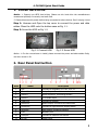
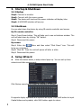
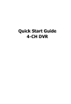
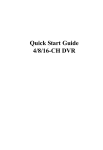
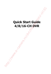
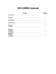
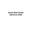
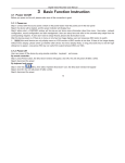
Quick Start Guide 4-CH NVR 4-CH NVR Quick Start Guide 1. Install Hard Drive Notice: 1. Support one SATA hard drives. Please use the hard drive the manufacturers recommend specially for security and safe field. 2. Please disconnect the power before being connected to other devices. Don't hot plug in/out Step 1: Unscrew and Open the top cover to connect the power and data cables. Place the HDD onto the bottom case as Fig 1-1. Step 2: Screw the HDD as Fig 1-2. Fig 1-1 Connect HDD Fig 1-2 Screw HDD Notice: 1. For the convenience to install, please connect the power and data cables firstly, and then screw to fix. 2. Rear Panel Instruction Item Name Description 1 K/B Connect to Keyboard, K is TX+, B is TX- 2 Alarm Out Relay Output. Connect to external alarm. 3 Alarm in Alarm Inputs for connecting sensors 4 Audio in 1 CH audio input 5 Video out Connect to monitor 6 Audio out Audio output, connect to the sound box 7 HDMI port Connect to high-definition display device 8 VGA port VGA output, connect to monitor 9 LAN Network port 10 USB port Connect to external USB mouse 11 DC12V Power input 1 4-CH NVR Quick Start Guide 3. Startup & Shutdown 3.1 Startup Step1: Step2: Step3: Step4: Connect to monitor. Connect with the source power. The device will boot and the power indicator will display blue. A WIZZARD window will pop up. 3.2 Shutdown You can shut down the device by using IR remote controller and mouse. By IR remote controller: Step1: Press Power button. This will take you to see a shutdown window. The unit will shut down by clicking “OK” button. Step2: Disconnect the power By mouse: Step1: Enter into Menu and then select “Shut Down” icon. This will bring up a shutdown. Step2: Click OK. Then the unit will power off after a while. Step3: Disconnect the power. 4. Setup Wizard After the device starts, a setup wizard pops up. You can set up time, network and disk management. Click Device name box to popup a keyboard as follows: It supports digits, alphabets and symbols as inputs. Click Shift button to input Capital letters and symbols; click Shift button again to return. 2 4-CH NVR Quick Start Guide Click „Next‟ button to bring up a network setup window. The default HTTP port is 80. The default server port is 6036. You can check „Obtain an IP address automatically‟ to acquire network information or input IP address, subnet mask, gateway, preferred/alternate DNS server manually. This function is used to monitor NVR through internet (See Section 10 for details). Click „Next‟ button. This will take you to the HDD management window. You can check your HDD information through this tab. If your HDD was recently installed, select the HDD from the list to format it. Click „Next‟ button. This will let you see your NVR status. And then Click „Finish‟ button to end this wizard. You can also refer to the complete setup steps from the relevant sections of NVR User Manual. If you don‟t want to setup Wizard, please click Exit button to exit. 5. Login After you exit the wizard setup, you can login to the NVR. Notice: This NVR can only display options on either VGA monitor or BNC monitor at a given point of time, if there is live image display without menu options, please check if there is display on other device/monitor, or long press ESC key to wait for login dialog box to appear. Long press ESC key can switch the output between BNC and VGA/HDMI. Press the MENU button which will bring the LOGIN dialogue box and enter the user name: admin and password: 123456 3 4-CH NVR Quick Start Guide 6. Main menu setup Click right mouse, or press ENTER button on the front panel to enter into the main menu. Then click Setup to enter into Setup interface as shown below. Basic configuration: Users can set video system, menu language, audio, time and authorization check. Live configuration:Users can set name/time display, picture color and hide cameras. Record configuration:Users can set record quality, frame rate, resolution, time stamp and recycle. Schedule configuration: Users can set schedule for timer, motion detection, and sensor alarm respectively. Alarm configuration: Users can set sensor type, alarm trigger and buzzer alarm. Network configuration: Users enable network function, and configure IP address, DDNS, transmission video parameters here. User configuration: Administrator can add, delete users, and change their authorization Advanced configuration: Users can reboot the device and import & export data into or from mobile storage medium. 7. Network Configuration 4 4-CH NVR Quick Start Guide In order to preview the live images from NVR, you must set up the network of NVR first and then add IP cameras. The NVR should be connected to a LAN/WAN or Internet. 7.1 On LAN Step 1: Set up the network of NVR. Enter into MenuSetupNetwork tab as shown below. Input HTTP Port (the default value is 80), Server port(the default value is 6036), IP address, Subnet, Gateway. If using DHCP, please enable DHCP in both the NVR and the router. Step 2: Click “Test” button to test the effectiveness of the network. After that, click “Apply” to save settings. Step 3: Enter into MenuIP Cameras tab as shown below. Click “Search” button to search the devices in the same network segment. Click “Refresh” button to refresh the searched devices. Check the device you want to add and then click “OK” button to return to the previous tab. The added devices will be listed. 5 4-CH NVR Quick Start Guide Step 4: Select the device and click “Setup” button to bring up the following window. Step 5: Check “Enable” checkbox, select channel and input the username and password of the device (see the User Manual of IP Camera for details). Then click “OK” button to return to the previous tab. Step 6: Click “Apply” button to save settings. Then exit the configuration tab. This will take you to see the live images. Note: The IP address of NVR and IP Cameras must be in the same network segment. 7.2 On WAN Step 1: Set up the network of NVR. Enter into MenuSetupNetwork tab as shown below. Input IP address, Subnet Mask, etc. If using DHCP, please enable DHCP in both the NVR and router. Or Enable PPPoE and then input user name and password received from your ISP. 6 4-CH NVR Quick Start Guide Step 2: Click “Test” button to test the effectiveness of the network. After that, click “Apply” to save settings. Step 3: Enter into MenuIP Cameras tab. Click “Add” button to add IP cameras. Step 4: Check “Enable” checkbox, select channel, manufacturer, product model and input IP address, server port, username and password of the device (see the User Manual of IP Camera for details). Then click “OK” button to return to the previous tab. Here the IP address must be a WAN IP address. If it is a LAN IP address, please forward the IP address and server port in the virtual server setup of the IP cameras’ router or virtual server. Note: IP address and port forwarding settings may be different in different routers. Please refer to the router’s manual for details. Step 5: Click “Apply” button to save settings. Then exit the configuration tab. This will take you to see the live images. 8. Recording Setup A user needs to install and format a HDD, and set all the recording parameters before recording. There are four kinds of record modes. 8.1 Manual Recording A user can press REC button on the front panel after quitting system setup. Press this button again to stop recording. Or press REC button on remote controller. Click it again to stop. Or click REC button on the tool bar with mouse. Click it again to stop. 8.2 Schedule Recording 7 4-CH NVR Quick Start Guide To Setup Schedule Recording: Step1: Enter into MenuSetupSchedule tab. Refer to the following picture. Step2: Click “ ” button to add a certain day schedule; click “ ” button to delete the selected schedule; Step 3: You can also double-click the grid to pop up a week schedule window. Select day and then click „Add‟ button to setup the start time and end time. Then select other days and click „Copy‟ button to save the setting to other days. Finally, click „OK‟ button to save week schedule. Step 4: Select other channels and set timeline for them or select „Apply Settings To All Channel and click “Copy” button to set the same settings for all channels. 8.3 Motion Based Recording Motion detection based recording: when there is a motion event detected, the camera will be triggered to record. To Setup Motion Based Recording: Step 1: Enter into MenuSetupScheduleMotion tab. The setup steps for schedule for motion based recording are similar to normal schedule setup. You can refer to 8.2 Schedule Recording for details. Step 2: Enter into MenuSetupAlarmMotionMotion tab as shown below. 8 4-CH NVR Quick Start Guide Step3: Enable motion alarm (Please specify to channel) and click „Apply‟ to save settings. Step4: Click „Setting‟ button under the Area to set Sensitivity and Detection area. Left click the grid and drag to delete the area. Drag again to add area. You can drag slide bar to set the sensitivity value (1-8). The higher the value is the more sensitive it is to motion. Since the sensitivity is influenced by color and time (day or night), you can adjust its value according to the practical conditions. Click icon to set the whole area as detection area. Click icon to clear the set detection area. Click icon to test the sensitivity as per the local conditions. Once motion is sensed, it displays a figure icon. Click icon to save the setting. Click icon to exit the current interface. Step 5: Enter into MenuSetupAlarmMotionSchedule tab to bring up schedule settings for motion alarm. The setup steps are similar to normal schedule setup. You can refer to 8.2 Schedule Recording for details. Note: The timelines of the two schedules must match, otherwise you cannot get the record in some time. 8.4 Sensor Based Recording To Setup sensor Based Recording: Step 1: Enter into MenuSetupScheduleSensor tab. The setup steps for schedule for sensor based recording are similar to normal schedule setup. You can refer to 8.2 Schedule Recording for details. 9 4-CH NVR Quick Start Guide Step 2: Enter into MenuSetupAlarmSensorBasic tab as shown below. Step 3: Enable sensor alarm (Please specify to channel), select senor type and click „Apply‟ to save settings. Step 4: Enter into MenuSetupAlarmSensorSchedule tab to bring up schedule settings for sensor alarm. The setup steps are similar to normal schedule setup. You can refer to 8.2 Schedule Recording for details. Note: The timelines of the two schedules must match, otherwise you cannot get the record in some time. 9. Playback This unit supports three kinds of playback 9.1 Live Playback Click Play button on the main menu bar to playback the record. User can do concrete operation by click the buttons on screen. 10 4-CH NVR Quick Start Guide 9.2 Playback by Time Search Step 1: Enter into MenuSearchTime Search tab. Step 2: Select date and channels on the right hand side and press “Search” button. A date with highlighted borderline indicates presence of data. Step 3: Set the start time by clicking a particular grid or by entering the specific value in the start time field. Step 4: Select the channel display mode and click Use the playback toolbar to control the playback. button to play record. 9.3 Playback by Event Search Step 1: Enter into MenuSearchEvent Search tab. Step 2: Select date and channels on the right hand side. A data with highlighted borderline indicates presence of data. Step 3: Then checkmark Motion, Sensor or All accordingly. You can search for motion based recording and sensor based recording. Step 4: Press “Search” button to display the searched event information in the event list box. Step 5: Double click the event item to play the record. 11 4-CH NVR Quick Start Guide 10. Back up This unit supports backup by USB flash,DVD writer and USB HDD. Step 1:Enter into MenuBackup tab. Step 2: Set the start & end time, select channels and click Search button to display the searched data in the data backup list box Step 3: Select a required file or checkmark “All” to select all data files. Click Backup button to pop up Backup information window. Step 4: In the backup information interface, user can check the relevant options for backing up files. These options include storage Media, backup player and save file type. Then click Start button to start backup. 11. Remote Surveillance In order to view the NVR from a network it must be connected to a LAN/WAN or internet. The network setup should be done accordingly. 11.1 Access NVR on LAN Enter into 12 Menu Information Network tab to check the network 4-CH NVR Quick Start Guide settings of the NVR. Enter into Record Setup to set network video parameters like resolution, frame rate etc. Open IE on a computer on the same network segment. Input the IP address of the NVR in IE address bar and press enter. If HTTP port is not 80, add the port number after IP address. IE will download ActiveX component automatically. Enter the username and password in the subsequent window. 11.2 Access NVR on WAN 1. Connect the NVR to internet through router or virtual server Enter into Menu Information Network tab to check the network settings of the NVR. Forward IP address and port number in Virtual Server setup of the router or virtual server. Configure the firewall to allow accessing the NVR. Open IE browser, input IP address, or dynamic domain name and enter. If HTTP port is not 80, add the port number after IP address. IE will download ActiveX automatically. Then a window pops up and asks for user name and password. Input name and password correctly, and enter to view. 2. Connect the NVR to Internet through PPPoE Enter into the NVR‟s MenuSetupNetwork interface to enable PPPoE and then input user name and password received from your ISP. Next, click „Apply‟. The NVR will connect to the server and would give a confirmation message. If users want to utilize dynamic domain name, please apply for a domain name in a DNS server supported by the NVR or router. Then add to the NVR or router. When accessing the remote interface of NVR, you can input WAN IP/domain name to access directly (user can enter into Main menuInformationNetwork interface to check IP address). If HTTP port is not 80, add the port number after IP address. The browser will download Active X control The following steps are the same as the connection way above. 450041000234 A0 13