1
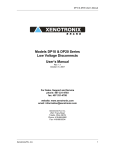
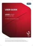
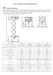
B R A N D
Model SX100-1
Automatic Battery Charger
User’s Manual
Rev. 1.0
October 17, 2006
THE EXTREME BATTERY CHARGER™
For Sales, Support and Service
phone: 407-331-4793
fax: 407-331-4708
website: www.xenotronix.com
email: [email protected]
Xenotronix/TLI, Inc.
2541 Tracy Road
Toledo, Ohio 43619
Phone: 419-666-6982
Fax: 419-666-6534
Warranty
Seller warrants that its products ("Product(s)") will meet the specifications set forth in its catalog
from time to time, unless the Buyer is notified otherwise prior to delivery. Seller will, without
charge, repair or provide a replacement for any of the Products which prove to be defective in
materials or workmanship within three (3) years from the date of shipment ("Warranty Period").
If, within the Warranty Period, Buyer discovers a defect in materials or workmanship which
interferes with the operation of any Product, Buyer must promptly notify Seller, in writing, of such
defect. Seller's sole obligation to Buyer under this Warranty is to repair and correct any defect in
material or workmanship, or provide a replacement Product to Buyer. Seller's decision with
respect to the applicability of this Warranty to any defect shall be final and conclusive. Seller
reserves the right to require Buyer, at Buyer's sole cost and expense, to return any defective
Product, including any alterations made thereto, F.O.B. Seller's factory in Ohio.
Seller does not warrant against abrasion, corrosion or erosion. Seller shall not be liable to Buyer or
to any other person for work done or repairs made, to remedy any defect, by any person who is not
an authorized representative of Seller, unless Seller's written consent is first obtained by Buyer.
This Warranty does not apply to, and is rendered null and void by, any Product which, after
leaving Seller's manufacturing plant: (a) is repaired or altered without Seller's prior written
approval; (b) is the subject of improper storage, installation or operation; (c) is the subject of
intentional or negligent misuse, misapplication, neglect or accident; or (d) is not used, repaired or
altered in accordance with Seller's written instructions.
Seller expressly reserves the right to declare this Warranty null and void upon Buyer's failure to
make full and timely payments with respect to any Products purchased by Buyer from Seller, in
which event all of Seller's obligations, and Buyer's rights, under this Warranty, shall immediately
terminate. SELLER DISCLAIMS THE IMPLIED WARRANTY OF MERCHANTABILITY
AND FITNESS FOR A PARTICULAR PURPOSE, AND ANY IMPLIED WARRANTIES
ARISING FROM COURSE OF PERFORMANCE, COURSE OF DEALING, OR USAGE OF
TRADE. SELLER SHALL NOT BE LIABLE TO BUYER OR ANY OTHER PARTY UNDER
THIS WARRANTY FOR DIRECT, SPECIAL, CONSEQUENTIAL, INDIRECT OR
INCIDENTAL DAMAGES OF ANY KIND.
Notice to the User
The information contained in this manual is believed to be correct. However,
Xenotronix/TLI, Inc. assumes no responsibility for any inaccuracies therein.
Information in this manual is subject to change without notice. No part of this manual may
be reproduced or transmitted in any form, electronic or mechanical, for any purpose, without
the express written permission of Xenotronix/TLI, Inc.
Copyright © 2006 Xenotronix/TLI, Inc. All rights reserved.
TABLE OF CONTENTS
Model SX100-1 Automatic Battery Charger – User’s Manual
Important Safety Instructions . . . . . . . . . . . . . . . . . . . . . . . . . . . . . . . . . . . . 1
Introduction . . . . . . . . . . . . . . . . . . . . . . . . . . . . . . . . . . . . . . . . . . . . . . . . . . 2
Operating Instructions . . . . . . . . . . . . . . . . . . . . . . . . . . . . . . . . . . . . . . . . . 2-6
Installation . . . . . . . . . . . . . . . . . . . . . . . . . . . . . . . . . . . . . . . . . . . . 3
Battery Type Switch . . . . . . . . . . . . . . . . . . . . . . . . . . . . . . . . . . . . . 3
Charge Program Switch . . . . . . . . . . . . . . . . . . . . . . . . . . . . . . . . . . 3
Powering Up the Charger . . . . . . . . . . . . . . . . . . . . . . . . . . . . . . . . . 3
Attaching the Battery . . . . . . . . . . . . . . . . . . . . . . . . . . . . . . . . . . . . 3-4
Condition Charge Stage . . . . . . . . . . . . . . . . . . . . . . . . . . . . . . . . . . 4
Bulk Charge Stage . . . . . . . . . . . . . . . . . . . . . . . . . . . . . . . . . . . . . . 4
Absorption Charge Stage . . . . . . . . . . . . . . . . . . . . . . . . . . . . . . . . . 4
Equalize Charge Stage . . . . . . . . . . . . . . . . . . . . . . . . . . . . . . . . . . . 4
Rest Stage . . . . . . . . . . . . . . . . . . . . . . . . . . . . . . . . . . . . . . . . . . . . . 5
Float Charge Stage . . . . . . . . . . . . . . . . . . . . . . . . . . . . . . . . . . . . . . 5
Battery Disconnect . . . . . . . . . . . . . . . . . . . . . . . . . . . . . . . . . . . . . . 6
Attaching Loads during Charge . . . . . . . . . . . . . . . . . . . . . . . . . . . . 6
Charger/Battery Fault Indication . . . . . . . . . . . . . . . . . . . . . . . . . . . 6
Temperature Fault Indication . . . . . . . . . . . . . . . . . . . . . . . . . . . . . . 6
Input Fuse . . . . . . . . . . . . . . . . . . . . . . . . . . . . . . . . . . . . . . . . . . . . . . . . . . . 6
Custom Units Note . . . . . . . . . . . . . . . . . . . . . . . . . . . . . . . . . . . . . . . . . . 6
Troubleshooting . . . . . . . . . . . . . . . . . . . . . . . . . . . . . . . . . . . . . . . . . . . . . . 6-7
Maintenance Instructions . . . . . . . . . . . . . . . . . . . . . . . . . . . . . . . . . . . . . . . 7
Options . . . . . . . . . . . . . . . . . . . . . . . . . . . . . . . . . . . . . . . . . . . . . . . . . . . . . 7
Battery Charger Specifications . . . . . . . . . . . . . . . . . . . . . . . . . . . . . . . . . . . 8
Dimensions . . . . . . . . . . . . . . . . . . . . . . . . . . . . . . . . . . . . . . . . . . . . . . . . . . 8
OPTIMIZER
TM
SX100-1 User’s Manual
IMPORTANT SAFETY INSTRUCTIONS
SAVE THESE INSTRUCTIONS - This manual contains important safety and operating
instructions for the Model SX100-1 Battery Charger (OPTIMIZER). Before using the
battery charger, please read all instructions and cautionary markings on the battery
charger, the battery, and the product using the battery.
CAUTION - To reduce the risk of electric shock:
o Do not expose unit to rain or moisture - use indoors only.
o Do not remove cover. There are no user serviceable parts inside. Refer service to
qualified service personnel.
o Connect the battery charger directly to a grounding receptacle. An adaptor should
not be used with this unit. This unit is equipped with a power cord having an
equipment grounding conductor and a grounding plug (3-prong). The plug must
be plugged into an outlet that has been properly installed and grounded in
accordance with all local and national codes and ordinances.
o Disconnect charger from AC power and battery before attempting any
maintenance or cleaning. Turning off controls may not reduce this risk.
WARNING
o Do not attempt to recharge non-rechargeable batteries. Charge only sealed or
valve regulated, lead-acid, non-automotive, maintenance free rechargeable
batteries. Attempting to charge other types of batteries may result in personal
injury and battery damage.
o The enclosure will become hot during the charge cycle - DO NOT TOUCH!
DANGER - Never alter power cord or plug provided. If it will not fit the outlet, replace
the power cord with one having the correct plug or have a proper outlet installed by an
electrician. Improper connection will result in the risk of an electric shock or fire.
Make sure cords are located so that they will not be stepped on, tripped over, or otherwise
subjected to damage or stress. Do not operate this unit with a damaged cord or plug replace them immediately. To reduce the risk of damage to electric plug, pull by plug
rather than cord when disconnecting unit.
Do not operate charger if it has received a sharp blow, been dropped, or otherwise
damaged in any way. Do not disassemble charger; incorrect reassembly will result in the
risk of an electric shock or fire. Refer service to qualified service personnel.
Recharge batteries in well ventilated areas to prevent build-up of explosive gases.
Allow space around unit and adequate air circulation to reduce internal heat buildup. Do
not place objects on top of the charger or restrict the airflow through the charger and do
not operate in a small, enclosed space.
Xenotronix/TLI
1
OPTIMIZER
TM
SX100-1 User’s Manual
INTRODUCTION
The OPTIMIZER has the best interests of
your battery in mind. It is a high quality
charger designed with efficient and reliable
switching technology for recharging Sealed
Lead-Acid (SLA) batteries. It is a true
constant current charger with precision
constant voltage regulation.
With a custom programmed microcontroller,
the charger is fully automatic with an
adaptive charge algorithm that will prevent
overcharging or undercharging your
batteries. The most widely recommended
charge algorithm by battery manufactures is
the 3-stage charge algorithm. This algorithm
has two-stage constant voltage and the
current is limited to the maximum specified. The OPTIMIZER uses an adaptive 3-stage
algorithm that scales the time spent in the absorption stage to the time spent in the bulk
stage. This helps prevent the battery from being undercharged or overcharged. A major
benefit of the 3-stage charging algorithm is that you don’t have to worry about
undercharging your battery if the application switches from stand by to cyclic; nor do you
have to worry about overcharging your battery in standby applications. In standby
applications the battery will be charged, topped-off, and maintained. In cyclic
applications the absorption charge will help ensure a complete charge and prevent
chronic undercharging, a leading cause of premature battery failure. The OPTIMIZER
also implements a light conditioning charge to ensure the battery is in good condition and
is able to accept a full current charge. There is also an optional equalize charge stage,
entered after the bulk charge and absorption charge stages, that allows the battery to be
more quickly charged in heavy-cyclic applications where there may not be enough time
to complete a standard charge cycle.
Equipped with a heavy-duty extruded aluminum heat sink enclosure to ensure field
reliability, this charger is designed to withstand rugged applications. Integral mounting
holes are included in the enclosure for securely mounting to a wall. The output cable is
heavy-duty parallel cable, size 16 AWG, 2-conductor, 6-feet long and is color coded red
for positive and black for negative. It is terminated with a polarized connector for mating
to a quick connect accessory harnesses. A harness with 6mm (1/4”) ring terminals for
connecting to ODYSSEY batteries is provided as standard equipment. Other harnesses
with larger rings, boots & clips, or custom connectors are available. The unit is protected
against reversed connection to a battery and shorted leads. The output is not activated
until the charger is properly attached to a battery. When the output connector is detached
from a battery, it may be live for 1 or 2 seconds until the output is deactivated. If the
charger is accidentally connected to a battery in a reversed condition, the charger will not
turn on and will not be damaged.
Xenotronix/TLI
2
OPTIMIZER
TM
SX100-1 User’s Manual
OPERATING INSTRUCTIONS
Before using this battery charger, make sure it is compatible with your battery. Refer to
the ratings on the battery charger, the specifications in this manual, and your battery
documentation. Charge only sealed or valve regulated, lead-acid, non-automotive,
maintenance free rechargeable batteries. Attempting to charge other types of batteries
may result in battery damage. If the battery is very hot or very cold, allow it to adjust to
room temperature before starting the charge.
Installation
For the best performance, mount the charger to a hard, flat, vertical surface near a
convenient power source and near the location of the battery to be charged (mounting
screws are not provided). Confirm the mounting surface is strong enough to hold the
charger in place using the screws you have selected. This charger should be located in a
dry location. A vertical mounting allows cooling air to flow through the charger and over
the heat sink fins. Do not operate the charger horizontally or it may over heat.
Battery Type Selection
A switch is provided for selecting between AGM (Odyssey) and Gel-Cell type batteries.
This switch should be set to your battery type before connecting the battery. If you
operate the switch during charge, if the charger is still in bulk mode (steady yellow LED),
then both the charge and float voltages will be changed. If the charger is in absorption
charge already (flashing yellow LED), of if it is already in float, then operating the switch
will only change the float voltage for the current charge.
Charge Program Switch
A switch is provided for selecting between the standard charge program and a special
program to be used in heavy-cyclic applications. The standard charge program is
recommended for all battery types, capacities, and applications - given adequate recharge
time. However, if you have a limited recharge time and the standard charge program is
not getting the battery charged in the time available, then the heavy-cyclic charge
program should be used. The charge mode should be selected before attaching the
battery, or during the bulk charge (steady yellow LED). The heavy-cyclic charge program
is not suitable for all battery types and capacities – consult your battery documentation.
Powering Up the Charger
Plug the charger into the proper power source as indicated on the unit. The charger does
not have a “power on” indicator and will not give any indications until a battery is
properly connected. To reduce sparks, the charger should be powered up before attaching
a battery. Otherwise, there may be a spark as the battery charges up the high frequency
capacitors inside the charger. In either case, the charger output remains off until a battery
is properly attached.
Attaching the Battery
Determine the battery polarity. Most batteries identify the positive terminal with a “+”
sign or the color red and identify the negative terminal with a “−” sign or the color black.
Xenotronix/TLI
3
OPTIMIZER
TM
SX100-1 User’s Manual
Attach the accessory harness to the battery noting the correct polarity. In some
applications, this will be a short cable with ring terminals and an insulated polarized
connector and may be permanently mounted to the battery. Connect the output cable to
the battery harness. Hooking up the cables in this order will contain any possible spark
within the insulated connector – not at the battery terminals. The output connector must
be attached to the battery for 1 second, continuously, before the battery is detected and
the charger turns on the output, lights the charge indicator, and begins charging the
battery. If the battery voltage is too high or too low, the charger will assume that an
incorrect voltage battery was installed and will display a fault. If the battery is attached in
a reverse condition, the charger will not be damaged but it will not detect the battery and
will not turn on.
Condition Charge Stage
Charging begins with a light conditioning charge, about 10% of the maximum charge
current, until the battery reaches 10.5 volts. This qualifies the battery by ensuring that it is
in proper condition to accept the full rated charge current before entering bulk charge.
Bulk Charge Stage
During bulk charge, the full rated current is delivered to the battery until the voltage rises
to the absorption voltage. The current will not decrease as the battery voltage climbs
above 12 volts. This offers a performance advantage over competitive products that
reduce in current as the battery voltage rises. Approximately 80% of the battery capacity
is returned during the bulk charge. The bulk charge ends when the charge voltage climbs
to the absorption voltage and the battery begins to accept less current.
Absorption Charge Stage
During the absorption charge, the charge voltage is regulated at a constant high rate and
the current drawn by the battery decreases as the battery becomes more charged. The
charge indicator will begin to flash upon entering the absorption charge mode. The time
spent during the absorption charge is proportional to the time spent during the bulk mode,
based on 3 times the time spent in bulk (1.5 times in heavy-cycle mode), and has a
minimum timer of 1 hour and a maximum timer of 8 hours (6 hours in heavy-cyclic
mode). After 1 hour, the absorption charge will also end when a minimum charge current
is detected. When the absorption charge ends the battery should be over 100% recharged.
A small overcharge is required to prevent chronic undercharging – a leading cause of
battery failure. At this point the charger will enter the float charge mode and the charge
indicator will darken and the ready indicator will light.
Equalize Charge Stage (heavy-cyclic mode only)
If the heavy-cyclic charge program is selected, the absorption charge will be shortened by
half and it will be supplemented with a constant current equalize charge lasting for 0.5 of
the time spent in bulk, or 1 hour max. The charge current is limited to 10% of the
maximum charge current. This charge program may not be appropriate for all battery
types and capacities. Consult your battery documentation.
Xenotronix/TLI
4
OPTIMIZER
TM
SX100-1 User’s Manual
Rest Stage (heavy-cyclic mode only)
After the equalize charge, the charger will enter a rest period for 1 hour before entering
float charge stage. During the rest period, the charger will indicate that the battery is
ready for use.
Float Charge Stage
During float charge, the voltage is regulated at a lower rate and the battery draws
whatever current is required to replace its standing losses. To maximize battery life, a
negative charge temperature coefficient of approximately 3.5mV per cell per °C variation
from 25°C is used. A precision temperature sensor monitors the temperature and as the
temperature increases the float voltage is reduced, and vise-versa. The minimum charge
voltage is limited to 13.2 volts during very warm conditions. Temperature compensation
helps offset the impact of high temperatures on the float life of the battery. To help your
battery keep its full capacity, we recommend the battery be left connected to the charger
in float charge mode until ready to use. This will prevent chronic undercharging, a
leading cause of premature battery failure. The float charge is low enough to prevent
overcharging, but high enough to allow the battery to replace its standing losses and
maintain a 100% state of charge. The battery may be left connected to the charger
indefinitely, in float charge mode, without danger of overcharging.
Battery Disconnect
At anytime during the charge or fault modes (except charger fault), if the battery is
disconnected the charger will reset the charge cycle and wait for a new battery to be
attached. For best performance, the battery should not be disconnected before entering
the ready mode. If it is necessary to pull a battery off of charge early, if possible wait for
the charger to enter the absorption mode. Repeatedly ending the charge early will lead to
premature battery failure very quickly due to chronic undercharging.
Attaching Loads to the Battery during Charge
When using parallel loads, allow the charger to cycle to ready before attaching the load.
This will ensure that the proportional timing charge algorithm fully charges the battery. If
heavy loads are attached to the battery during charge, the charger may not properly cycle
out of the charge modes and may indicate a battery fault and turn off the charger. Light
loads will have little effect other than robbing charge current and lengthening the charge
cycle. During the float charge, if the parallel load causes the charger to deliver its full
current, the charge indicator will light in addition to the ready light. In this condition, the
battery is not being charged and is probably being discharged. This is OK as long as time
is provided at a reduced load for the charger to replace the current drawn from the
battery. Heavy loads permanently attached during float charge will cause the charger to
warm and may affect the temperature reading and depress the float charge voltage. Use a
larger charger with heavier loads.
Charger / Battery Fault Indications
Charger and battery faults are indicated by quickly and alternately flashing the charge
and ready indicators. A charger fault occurs when the charger output is on when it should
be turned off. A charger fault is permanent. To confirm a charger fault, with no battery
Xenotronix/TLI
5
OPTIMIZER
TM
SX100-1 User’s Manual
attached, unplug the charger, wait a few seconds until all lights are off, and plug the
charger back into AC power. If the charger is damaged, it will indicate a fault after
several seconds. Battery faults occur if the battery voltage is too high or too low, or if the
charger spends more than 24 hours in bulk (indicating a possibly damaged battery).
Battery faults are cleared by disconnecting the battery.
Temperature Fault Indication
Temperature faults are indicated by double flashing the charge indicator. While charging,
if the internal charger temperature becomes excessively hot, it will pause charging and
display a temperature fault. The charger will stop indicating a temperature fault when the
charger temperature cools. During charge, temperature faults may be caused by the
ambient temperature around the unit becoming very warm, if the charger vents are
blocked, if the charger is operated in a horizontal orientation, and possibly if the charger
is damaged. The charger will also display a temperature fault if the ambient temperature
becomes too hot to safely maintain a battery on float charge.
Input Fuse
This charger is equipped with a non-user-replaceable fuse. If the charge indicator does
not light when the battery is attached, first check to see that the output cable is not
reversed on the battery and that the power source is not controlled by a light switch, etc.
If the fuse is blown, the charger must be returned for service. The fuse value is selected to
avoid nuisance trips and should only blow if the charger is damaged. The fuse may also
blow due to high temperatures.
CUSTOM UNITS NOTE
Xenotronix/TLI can make custom units, or modify our existing units, to exactly match
your charging needs. Call our sales department for technical information and pricing.
Following are some of the modifications we can perform:
o Reduce charge current to match your battery capacity
o Change the low rate current to match battery and charge rate
o Adjust float and charge voltages for special conditions or batteries
o Change charge times and timers
o Provide custom cables and connectors
o Private labeling
TROUBLESHOOTING
CHARGER DOES NOT START (no indicators) – Check to see if the receptacle is
controlled by a light switch or power strip switch and verify the connection is good and
the battery is not reversed. If the battery is below 1V it will not be detected by the charger
and is probably damaged to accept a charge.
Xenotronix/TLI
6
OPTIMIZER
TM
SX100-1 User’s Manual
BATTERY FAULT WHEN 12V BATTERY IS ATTACHED – This occurs if the battery
voltage is too low or too high. If you know you have a 12V battery, and not a 6V or 24V
battery, check the battery voltage using a volt meter. If the battery has been so severely
discharge that it remains below 8V even with the load removed, then the charger will
assume it is a 6V battery and indicate a fault. A 12V battery that remains less than 8V is
probably damaged and will not accept a charge. The battery may also be sulfated of have
open cells. In this case the battery voltage will climb very high when current it applied.
These batteries are damaged and can not be charged.
FORCING A CHARGE ON A LOW VOLTAGE BATTERY – The charger will not
normally attempt to charge very low voltage batteries. When either the battery is so low
in voltage that it can not be detected, or it is detected but the charger assumes it is an
incorrect voltage battery, the charger will not start and may indicate a battery fault. If you
with to attempt a charge anyway, the battery must be brought to above 8V. They may be
done using a simple automotive type battery charger or by temporarily attaching a good
battery in parallel with the discharged battery (jumping). When the charger sees the
correct voltage it will remove the fault and enter charge – the “jumping” battery or
charger may be removed. It is likely that the battery has already been severely damaged,
but some useful capacity may be recovered.
MAINTENANCE
Inspection
Periodically inspect the AC power cord and the DC output cable for visible signs of
damage such as cuts and abrasions, or bent pins and damaged connectors. Do not operate
the charger with damaged cables – replace them immediately.
Cleaning
Unplug the charger and disconnect the battery before attempting any cleaning. If it
becomes necessary to clean the enclosure, wipe the enclosure exterior with a damp cloth.
If necessary, use a mild detergent. Do not use an abrasive cleanser or spray cleaners
directly onto the charger. Do not immerse unit in water.
OPTIONS
The OPTIMIZER may be ordered in a 230 VAC input version with a European “Schuko”
plug and a switch selectable 115/230 VAC input version having the standard plug.
Xenotronix/TLI
7
OPTIMIZER
TM
SX100-1 User’s Manual
BATTERY CHARGER SPECIFICATIONS
General Conditions
Ambient Temperature = 25ºC (77ºF)
Operating Temperature
Storage Temperature
Input Power Requirements
Maximum Charge Current
Absorption Charge Voltage
Float Charge Voltage
Condition / Equalize Current
Equalize Charge Voltage
Battery
Input Cable
Output Cable
0 to 50ºC (32 to 122ºF)
-40 to 80ºC (-40 to 176ºF)
110-127 VAC, 50-60Hz, 1.3A
7A
14.70 Vdc (AGM) 14.10 Vdc (GEL)
13.62 Vdc (AGM) 13.50 Vdc (GEL)
approx. 700 mA
15.60 Vdc
12-Volts, Sealed Lead-Acid
3/18 AWG, 6’ long with NEMA 5-15P plug
2/16 AWG, 6’ long with polarized connector,
(harness with 6mm (1/4”) ring terminals included)
extruded aluminum heat sinking chassis
yellow LED = Charge; green LED = Ready
6.50” (16.5 cm) x 6.40” (16.3 cm) x 2.00” (5.1 cm)
2.65 lbs (1.2 kg)
Enclosure
Indicators
Dimensions (L x W x H)
Weight (including cables)
DIMENSIONS
6.40
6.00
2.00
6.50
4.00
Xenotronix/TLI
8