1
JM Badge Board
User Manual
Rev. H
Freescale Semiconductor Inc.
Microcontroller Solutions Group
Contents
1 Purpose .......................................................................................................................................................3
2 Related Documents.................................................................................................................................3
3 Hardware Overview................................................................................................................................3
3.1 MCF51JM128 Microcontroller.......................................................................................................................................4
3.2 Power Supply........................................................................................................................................................................5
3.2.1 Li‐Ion Battery.......................................................................................................................................................................................6
3.2.2 USB VBUS...............................................................................................................................................................................................7
3.3 System Clocks.......................................................................................................................................................................7
3.4 USB Interface ........................................................................................................................................................................7
3.5 LED Matrix Display.............................................................................................................................................................7
3.6 Proximity Capacitive Touch Sensor ............................................................................................................................8
3.7 Ambient Light Sensor........................................................................................................................................................8
3.8 Three‐axis Accelerometer ...............................................................................................................................................8
3.9 Expansion Connector ........................................................................................................................................................8
3.10 Debug Interface.................................................................................................................................................................9
4 Software Overview............................................................................................................................... 10
4.1 Using the Badge ................................................................................................................................................................ 10
4.1.1 Unlock the Badge............................................................................................................................................................................. 10
4.1.2 Sleep Mode ......................................................................................................................................................................................... 10
4.1.3 USB Mode............................................................................................................................................................................................ 10
4.1.4 Recharging the Battery................................................................................................................................................................. 10
4.2 Demo Software.................................................................................................................................................................. 11
4.2.1 Badge Board Applications........................................................................................................................................................... 11
4.2.2 USB Applications ............................................................................................................................................................................. 13
4.3 Bootloader .......................................................................................................................................................................... 15
4.3.1 Obtaining the S19 file .................................................................................................................................................................... 15
4.3.2 Using the Bootloader ..................................................................................................................................................................... 15
4.4 Creating an Application for the Badge .................................................................................................................... 16
4.4.1 Software Requirements................................................................................................................................................................ 16
4.4.2 Loading Application onto Badge Board ................................................................................................................................ 17
4.4.3 Initialization code ........................................................................................................................................................................... 17
4.4.4 Useful Information.......................................................................................................................................................................... 17
Microsoft and Windows are either registered trademarks or trademarks of Microsoft Corporation in the U.S.A. and/or other
countries. All other trademarks are property of their respective owners.
JM Badge Board User Manual
Page 2 of 19
1
Purpose
This document provides design and usage information for the Freescale JM Badge Board. This
demonstration and evaluation board features a MCF51JM128 ColdFire® V1 microcontroller, a
MPR083/4 proximity capacitive touch sensor, a MMA7260QT three‐axis accelerometer, and a
MC34673 Li‐Ion battery charger.
2
Related Documents
The documents listed below should be referenced for more information when developing with the JM
Badge Board.
• MCF51JM128RM – Microcontroller Reference Manual
• MCF51JM128 – Microcontroller Data Sheet
• MPR083 – Proximity Capacitive Touch Sensor Controller Data Sheet
• MPR084 – Proximity Capacitive Touch Sensor Controller Data Sheet
• MMA7260QT – Three Axis Low‐g Accelerometer Data Sheet
• MC34673 – Li‐Ion Battery Charger Data Sheet
3
Hardware Overview
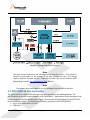
Figure 1 below shows a high‐level block diagram of the system. The major features of the JM Badge
Board include:
• ColdFire V1 microcontroller
• Powered by USB or rechargeable battery
• USB device interface
• Three‐axis accelerometer
• Capacitive touch sensor with 8 touch points
• LED matrix display
• SD card slot
• Magnetic Buzzer
JM Badge Board User Manual
Page 3 of 19
Figure 1. JM Badge Board Block Diagram
Note
The touch sensor featured on the JM Badge Board varies by revision. The revision is
marked on each board at the bottom of the back (component) side. This change
requires different firmware drivers. Take care to select the correct software when
downloading from the Can Your Badge Do This? website.
Note
The ambient light sensor appears only on JM Badge Boards revision D and later.
3.1 MCF51JM128 Microcontroller
The MCF51JM128 in a 64‐pin LQFP package is the host controller for the JM Badge Board. The
MCF51JM devices are the newest members of the Flexis family. These devices are pin, peripheral, and
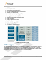
toolset compatible with the S08JM family. Figure 2 show a top‐level block diagram of the MCF51JM
family of microcontrollers. The following is a summary of features of the MCF51JM128.
• Up to 50.33 MHz ColdFire V1 core
• 128K flash
JM Badge Board User Manual
Page 4 of 19
•
•
•
•
•
•
•
•
•
•
•
•
•
•
•
16K RAM
Four low‐power modes
Multi‐purpose clock generator (MCG)
Dual‐role Full‐speed USB Controller and transceiver
Controller Area Network (CAN)
Two serial communications interfaces (SCI)
Two serial peripheral interfaces (SPI)
Cryptographic acceleration unit (CAU)
Random number generator accelerator (RNGA)
Analog comparators
Analog‐to‐digital converter (ADC)
Two I2C interfaces
Carrier modulation timer (CMT)
Two timer modules (TPM)
Up to 66 GPIOs and 16 Rapid GPIOs
Figure 2. MCF51JM Block Diagram
3.2 Power Supply
The JM Badge Board can be powered by a rechargeable Li‐Ion battery or the USB interface. The typical
voltage supply range of a Li‐ion battery is 3.1‐4.2V. The USB VBUS supply is 5V +/‐ 5%. In order to
accommodate the operating voltage of all the devices on the JM Badge Board (refer to Table 1 below),
a low‐dropout (LDO) regulator is used to maintain a 3.3V operating voltage.
JM Badge Board User Manual
Page 5 of 19
Table 1. Voltage Supply Requirements
Device
MCF51JM
MMA7260QT
MPR083/4
Voltage
2.7V – 5.5V
3.9V – 5.5V
2.2V – 3.6V
1.8V – 3.6V
Notes
When internal USB regulator is off.
When internal USB regulator is on.
3.2.1 Li-Ion Battery
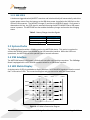
The JM Badge Board is equipped with a rechargeable Lithium‐ion battery, LIR2430. The typical
specifications for the battery are shown in Table 2 below. The typical charge and discharge voltage
vs. capacity graph is shown in below.
Table 2. Typical LIR2430 Battery Specifications
Specification
Capacity
Nominal Voltage
Max. Discharge Current
Max. Charge Current
Value
65mAh
3.7V
110mA
55mA
Figure 3. LIR2430 Voltage vs. Capacity
The ON/OFF switch, SW1, can be used to isolate the battery from all circuitry except the MC34673
charger. While in the OFF position, the JM Badge Board will not be able to run from the battery,
but the board can still be powered from the USB interface.
JM Badge Board User Manual
Page 6 of 19
3.2.2 USB VBUS
A hardware‐triggered switch (MOSFET transistor and isolation diode) will automatically switch the
system power source from the battery to the USB when power is applied to the VBUS pin on the
USB mini‐AB connector. The MC34673 charger IC monitors the USB VBUS supply. Once power is
detected on this line, the /PPR signal is asserted informing the MCF51JM MCU that a USB power
source is present. The MCF51JM can then enable the battery charger and monitor the charging
status.
Table 3. Battery Charger Interface Signals
MC34673 Signal
/PPR – Power Present
/EN ‐ Enable
/CHG ‐ Charging
MCF51JM Signal
PTG1
PTG2
PTG0
3.3 System Clocks
The JM Badge Board provides a 12MHz crystal to the MCF51JM device. This option is required to
achieve the 48 MHz system clock needed by the USB controller interface. When the USB is not
operational, the MCF51JM can also operate from its internal reference.
3.4 USB Interface
The MCF51JM features a full‐speed USB dual‐role controller with on‐chip transceiver. The JM Badge
Board is equipped with a mini‐AB USB connector wired for a USB device interface.
3.5 LED Matrix Display
A simple matrix of LEDs is provided as a display interface. MCF51JM GPIO signals are used to control
the 5 x 16 matrix of LEDs. The connection diagram and pin connection table are shown below.
COL0
ROW0
ROW1
ROW2
ROW3
ROW4
COL1
COL2
COL15
360
360
360
360
360
Figure 4. LED Matrix Connection Diagram
JM Badge Board User Manual
Page 7 of 19
Table 4. LED Matrix to MCU Port Pin Mapping
Row
ROW0
ROW1
ROW2
ROW3
ROW4
MCU Port
Pin
PTA0
PTA1
PTA2
PTA3
PTA4
Column
COL0
COL1
COL2
COL3
COL4
COL5
COL6
COL7
MCU Port
Pin
PTE0
PTE1
PTE2
PTE3
PTE4
PTE5
PTE6
PTE7
Column
COL8
COL9
COL10
COL11
COL12
COL13
COL14
COL15
MCU Port
Pin
PTD0
PTD1
PTD2
PTD3
PTD4
PTD5
PTD6
PTD7
3.6 Proximity Capacitive Touch Sensor
Eight touch sensitive electrodes provide the primary user interface on the JM Badge Board. Revision B
of the board features a MPR083, while later revisions feature a MPR084. These touch sensors detects
capacitance changes on the eight electrodes and provides touch information to the MCU via the I2C
bus.
Note
The touch sensor featured on the JM Badge Board varies by revision. The revision is
marked on each board at the bottom of the back (component) side. This change
requires different firmware drivers. Take care to select the correct software when
downloading from the Can Your Badge Do This? website.
3.7 Ambient Light Sensor
An ambient light sensor is provided on JM Badge Boards starting with revision D. The light sensor
outputs an analog signal that is measured by an analog‐to‐digital channel to determine the amount of
ambient light that the sensor is detecting. Refer to the Avago APDS‐9002 Data Sheet for more
information.
3.8 Three-axis Accelerometer
A MMA7260QT three‐axis, low‐g accelerometer is featured on the JM Badge Board. Each axis has a
dedicated analog output that is connected to an ADC channel on the MCF51JM.
3.9 Expansion Connector
An unpopulated 30x2, 100 mil, through‐hole header allows access to most MCF51JM signals for
probing and expansion. The header pinout and dimensions match that of the MCU_PORT on the
DEMOJM baseboard. The table below provides the pinout information.
JM Badge Board User Manual
Page 8 of 19
Table 5. MCU_PORT Pin Assignment
Connection
VREG
GND
PTE0/TXD1
PTE1/RXD1
PTG0/KBIP0
PTG1/KBIP1
PTE2/TPM1CH0
PTE3/TPM1CH1
PTE5/MOSI1
PTE4/MISO1
PTE6/SPSCK1
PTE7/SS1
PTF0/TPM1CH2
PTF1/TPM1CH3
PTF2/TPM1CH4
PTF3/TPM1CH5
VREFH
VREFL
PTD0/ADP8/ACMP+
PTD1/ADP9/ACMP‐
PTD2/KBIP2/ACMPO
PTD3/KBIP3/ADP10
PTD4/ADP11
PTD5
PTD6
PTD7
PTC2
PTC4
PTC6
–
Pin
1
3
5
7
9
11
13
15
17
19
21
23
25
27
29
31
33
35
37
39
41
43
45
47
49
51
53
55
57
59
2
4
6
8
10
12
14
16
18
20
22
24
26
28
30
32
34
36
38
40
42
44
46
48
50
52
54
56
58
60
Connection
IRQ/TPMCLK
RESET
BKGD/MS
VUSB33
PTB0/MISO2/ADP0
PTB1/MOSI2/ADP1
PTB2/SPSCK2/ADP2
PTB3/SS2/ADP3
PTB4/KBIP4/ADP4
PTB5/KBIP5/ADP5
PTB6/ADP6
PTB7/ADP7
PTC0/SCL
PTC1/SDA
PTG2/KBIP6
PTG3/KBIP7
PTF4/TPM2CH0
PTF5/TPM2CH1
PTC5/RxD2
PTC3/TxD2
PTG4/XTAL
PTG5/EXTAL
PTA0
PTA1
PTA2
PTA3
PTA4
PTA5
PTF6
PTF7
3.10 Debug Interface
The standard 6‐pin (2x3, 100 mil) ColdFire V1 BDM interface header is available but not populated.
The pinout is shown below.
Table 6. BDM Connector
Pin Connection
1
BKGD/MS
2
GND
3
–
4
RESET
Note
Pulled up to VBATT via 4.7K ohm
Pulled up to VBATT via 4.7K ohm
JM Badge Board User Manual
Page 9 of 19
5
6
4
–
VBATT
Software Overview
The JM Badge Board has been loaded with a demo applications and a USB bootloader that will
enumerate as a USB mass storage device. The following sections provide more information on the
usage of the demo and bootloader and how to create custom applications.
4.1 Using the Badge
To start using the badge, move the switch, SW1, to the “On” position. A message will start scrolling
across the LED matrix. This message can be edited by using the Message Edit application described in
Section 4.2.1.1.
4.1.1 Unlock the Badge
To start using the demo applications on your badge, “unlock” it by sliding your finger down the left
hand side buttons from E1 down to E4.
Make sure your finger makes good contact with each button to ensure it is detected. Then press
the button of the desired application. See Section 4.2.1 for more information on the different
applications available.
4.1.2 Sleep Mode
After a prolonged period of inactivity, the badge will go into a sleep mode to conserve power.
During this mode, a single LED will flash on and off. Press and hold any button on the badge to
wake it up.
4.1.3 USB Mode
Connect the badge to a computer via the included USB cable to use the bootloader or USB demos.
Upon connection to the computer, a message stating “Press E4 for bootloader” will scroll by.
Press E4 to launch the bootloader. See Section 4.3 for more information on using the bootloader.
Press any other key or wait for the message to scroll past to launch the USB demos. See Section
4.2.2 for more information.
Anytime the board is connected to a USB Host, it will be recharging the battery.
4.1.4 Recharging the Battery
The badge board uses a rechargeable Lithium‐Ion battery for its power source. The battery will last
about 24 hours while continuously scrolling an LED message. It is recommended to recharge it each
night to ensure it will work the entire next day.
JM Badge Board User Manual
Page 10 of 19
The battery can be recharged by connecting it to a computer USB port. While the battery is
charging, the single LED on the far left side of the badge will be red. When the battery is fully
charged, the LED will turn green
4.2 Demo Software
The badge board comes with some default demo programs. More applications can be downloaded by
registering at the Can Your Badge Do This? website (http://www.canyourbadgedothis.com).
The applications can be divided up into two types: Those that can be run using only the badge board,
and those that only run when connected via the USB cable to a USB Host.
4.2.1 Badge Board Applications
These applications are only available when the badge is not connected to a USB source.
After unlocking the board (see Section 4.1.1), “Demos” will scroll across the screen. Press the
associated button to access that particular application. If you do not have that application, it will go
back to the default scrolling message screen.
4.2.1.1 Message Edit (Button E1)
Enter your customized message by using:
• E1 to scroll through characters
• E2 to scroll through characters in the reverse direction
• E3 to toggle caps lock (only affects A‐Z characters)
• E5 to select a character
• E6 to delete the last character
When finished, you may:
• Press E8 to save your custom message and exit the Message Edit application
• Press E4 to exit without saving
The characters scroll through A‐Z, then special symbols, then numbers 0‐9, and finally “space”.
4.2.1.2 Scroll Speed (Button E2)
Change the speed at which the message scrolls on the LED matrix display.
• Press E1 to speed up
• Press E2 to slow down
• Press E3 to return to the default speed
• Press E8 to exit the application
Other button presses are ignored
JM Badge Board User Manual
Page 11 of 19
4.2.1.3 Shake Test (Button E3)
This application uses the accelerometer to measure how hard you can shake the badge board.
The opening message can be skipped by pressing any key.
A single bar of LED’s will show up on the left hand side. Shake the board side‐to‐side for five
seconds and notice that the harder the board is shaken, the further the bar moves to the right.
After five seconds, “Results:” will scroll across the screen followed by a message describing how
well you did. The application will then go back to the default scrolling message.
4.2.1.4 Tilt (Button E4)
This application uses the accelerometer to determine how the badge board is being tilted, and
moves a “dot” around the LED matrix accordingly.
After launching the application, “Tilt” will scroll across the screen. Hold the board either flat or
upright at this time to get the best result. Once a single LED is turned on in the center of the
LED matrix, tilt the board around to see how it reacts. Press E8 to exit.
4.2.1.5 Magic Badge (Button E5)
Find out the answer to all life’s questions or just figure out what you should do on your next
business deal. Ask the Magic Badge! It’s powered by secret Freescale technology.
The badge will ask you to think of any yes‐or‐no question. Then once you’re ready, shake it up
and down a few times, and the answer will appear. Repeat until all of life’s mysteries have been
solved. Press E8 to exit.
4.2.1.6 Paddle Ball (Button E6)
Keep the ball from falling into the abyss! After launching the application, it will ask you to select
a speed to play at. Press E1 for the fastest, E2 for second fastest, etc. E8 is the slowest. By
default it will be set at E6 if no button is pressed by the end of the message.
• Press E4 to move the paddle to the left by one space.
• Press E8 to move the paddle to the right by one space.
• Press E1 to exit the application.
4.2.1.7 Side Ball (Button E7)
This application can be obtained by registering at http://canyourbadgedothis.com
After launching the application, it will ask you to select a speed to play at. Press E1 for the
fastest, E2 for second fastest, etc. E8 is the slowest. By default it will be set at E6 if no button is
pressed by the end of the message. The game controls are as follows:
• Move your finger along the left side to move the left paddle up and down
• Move your finger along the right side to move the right paddle up and down
To exit, press, in order, E1, E5, E4, and E8. (Or just power‐cycle the board)
JM Badge Board User Manual
Page 12 of 19
4.2.1.8 Exit (Button E8)
Exit the demo mode selection screen
4.2.2 USB Applications
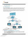
When the board is plugged into a USB Host, a scrolling message, which indicates that action must
be taken to enter the boot loader, appears on the LED matrix. If no action is taken before the
scrolling message ends, the boot loader message disappears, and the board firmware will wait
indefinitely for the user to activate a proximity switch. Pressing switch E5 starts the Freescale HID
Mouse demo and pressing switch E8 starts the Windows 7 Sensor demo. Pressing any other
proximity switch will have no effect.
Connect the JM Badge Board to a
USB Host
“Press E4
for
bootloader”
message
User Input
E4 Pressed
Time out or key other
than E4 pressed
Bootloader Mode
User Input
E5 Pressed
E8 Pressed
HID Mouse and
Music Demo
Windows 7 Sensor
Platform Demo
Figure 5. USB Mode and Demo Selection Flow Diagram
Refer to Section 4.3 for information on the USB Bootloader.
4.2.2.1 Demo Application for the Windows 7 Sensor Platform
To use this demo, install the associated Windows 7 driver that is included on the JM Badge
Board DVD. For more information about this demo, see Sensor Development Kit Driver and
Firmware.rtf which is included on the DVD.
JM Badge Board User Manual
Page 13 of 19
When the Windows 7 Sensor demo has been selected, the upper‐left LED in the LED matrix
should blink quickly to indicate that the firmware is running. When sensors are acquiring and
reporting data, the LED on the lower‐left side of the LED matrix will blink to show the rate of
data acquisition. By default, the board will send sensor samples to the host computer.
Note
The Windows 7 Badge Sensor driver must be installed prior to running
this demo. Once properly installed, the device will appear in the device
manager as both a USB HID device and as a Windows Sensor device.
To exit, unplug the badge board from the USB port.
For more information about the Sensor Platform for Windows 7, visit:
http://www.microsoft.com/whdc/sensors
4.2.2.2 HID Mouse Demo
In this demo, the badge will enumerate as a HID‐compliant 3 button mouse. Tilt the board to
move the mouse cursor around. Tilt it at a slight angle to slowly move the pointer, or tilt it at a
more severe angle to make the cursor move faster.
• E1 produces a left click
• E2 produces a right click
• E3 produces a middle click
Unplug the badge board from the USB connection to exit.
4.2.2.3 Music Demo
This application uses the magnetic buzzer to create different tones using a PWM channel. This
application draws high amounts of current; therefore, the badge must be connected to and
powered by a USB Host instead of the battery.
While connected as a mouse, press E8 to exit that demo and start the music demo. Each button
corresponds to a different note:
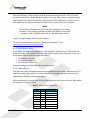
Table 7. Music Demo Frequencies
Button
1
2
3
4
5
6
7
8
Note
A
B
C
D
E
F
G
A
Frequency
440 Hz
494 Hz
523 Hz
587 Hz
659 Hz
698 Hz
784 Hz
880 Hz
JM Badge Board User Manual
Page 14 of 19
Unplug the badge board from the USB connection to exit.
4.3 Bootloader
One of the major features of the JM Badge Board is that it includes a USB bootloader that allows
simple “drag and drop” reprogramming. This section will describe how to use the bootloader. Please
see the Errata document for important information about the s19 files that the bootloader can accept.
4.3.1 Obtaining the S19 file
The bootloader accepts srecord or S19 files that it uses to program the board. In the example
projects this file can be found in the <project directory>/bin/ folder and will end in a “.s19” file
extension. This file will get overwritten every time the project is compiled.
To create an S19 file, click on the “Standard Settings…” button on your project, and look for the
Linker category. Select “ColdFire Linker” and make sure that the “Generate S‐Record File” option is
checked. Also make sure that the “Max S‐Record Length” field is set to 32. The example projects on
the Can Your Badge Do This? website are already set up to create an S19 file.
Note that not just any S19 file will work correctly with the badge board. The software that
produced the S19 file must follow certain guidelines outlined in Section 4.4. The S19 files provided
on the Can Your Badge Do This? website will correctly download to the board and can be used to
test out the bootloader.
4.3.2 Using the Bootloader
With the badge turned off, plug the badge into a Windows computer. A message stating “Press E4
for bootloader” will scroll by. Press E4 before the end of that message, otherwise the USB demos
will launch instead (see Section 4.2.2).
The badge board will then enumerate as a Mass Storage Device. The far left column of the LED
matrix will blink as it enumerates and will remain steady once it is connected.. Inside the newly
added storage device, there will be an empty file named “READY.TXT”.
JM Badge Board User Manual
Page 15 of 19
Copy and paste the S19 file into the enumerated drive. Upon successful programming, the left two
columns on the badge will light up and the S19 file will appear on the removable drive.
Unplug the badge board from the USB connection. The board has now been updated.
If an error occurred, the left four columns on the badge will light up.
The badge must be turned on and run off battery power at least once before using one of the USB
applications.
4.4 Creating an Application for the Badge
To create software that can be downloaded to the badge using the bootloader, there are a few
guidelines that must be met. The LEDApp.zip and JM_Badge_Board.zip CodeWarrior projects have
been provided as templates for development. It is highly recommended to start custom software
designs with one of those projects.
4.4.1 Software Requirements
There are several important things that must be done for a custom application to download and
work correctly with the badge bootloader. This includes setting up the interrupts, ensuring the
code is called from the correct place, and checking the code size.
4.4.1.1 Interrupts
All interrupts that will be used in the project must be declared in the main.c file. This file can be
found in <Project Directory>/Sources/main.c
In that file, there is an array called “RAM_vector[]” that contains the re‐directs to all the
interrupt handler routines. For the interrupt that is to be used, replace “dummy_ISR” with the
name of the interrupt function that should be used instead.
For example, in the LED_App project, the RTC interrupt (Vector 91) is using the “rtc_interrupt”
function. This function will be called any time an RTC interrupt occurs. This is the only change
that is required that is specific to the badge board in order to use interrupts.
JM Badge Board User Manual
Page 16 of 19
4.4.1.2 Application Code
All user application code must be called from a specific place in main.c. This file can be found in
<Project Directory>/Sources/main.c
In the main(void) function, there are two large comment blocks that signal the beginning and
end of where the application code should begin and end executing. The code may call any
functions from within this block, so there is no need to put all the code in the main.c file.
4.4.1.3 Code Size
As can be seen in the project.lcf linker file, the bootloader takes up the flash addresses from
0x00000000 to 0x00003800. This leaves addresses 0x00003800 to 0x00020000 for application
code. There is also 0x3E00 bytes of RAM space available located from 0x00800200 to
0x00804000. See the linker file for more information.
4.4.2 Loading Application onto Badge Board
See Section 4.3.1 for how to use get an S19 file and load it on the board.
4.4.3 Initialization code
It is highly recommended to keep the sys_init() function from the sample projects when developing
custom projects. This sets up the GPIO pins correctly for the badge board, and ensures very low
power consumption. Certain pins (particularly PTF2, which is connected to the magnetic buzzer),
can have very dramatic affects on current draw.
Note that the initialization function turns off all system clocks except KBI and IRQ. The other
module clocks are only turned on when needed. See the SCGC1, SCGC2, and SCGC3 register
descriptions in Section 5.7.8 of the MCF51JM128 Reference Manual for more information.
The clock is also set up to use Bypassed Low Power External (BLPE) mode, with a bus clock speed of
750 Hz. See Chapter 7 of the MCF51JM128 Reference Manual for more information.
4.4.4 Useful Information
The JM_Badge_Board.zip project contains sample code for using the touch sensor, accelerometer,
battery charger, speaker, and scrolling messages across the LED Matrix. This should help get
custom designs up and running quickly.
For simple debugging, you can use the LED Matrix. PTAD controls which rows are activated.
• PTAD=0x00 means no LEDs will light up.
• PTAD=0x01 will activate the 1st row.
• PTAD=0x02 will activate the 2nd row
• PTAD=0x1F will activate all the rows.
JM Badge Board User Manual
Page 17 of 19
PTED and PTDD control which column is lit. PTED controls the left 8 columns. PTDD controls the
right 8 columns. First negate the value to display, and then hold the badge upside‐down to
correctly read the value.
• PTED=~(0x01) will light up the left most column (Column #1)
• PTED=~(0x03) will light up the two left most columns (Columns #1 and #2)
• PTDD=~(0x80) will light up the right most column (Column #16)
• PTDD=~(0x01) will light up column #9
See the Badge Errata page for important information on issues with the bootloader and
workarounds.
JM Badge Board User Manual
Page 18 of 19
Freescale™ and the Freescale logo are trademarks of
Freescale Semiconductor, Inc. All other product or service names
are the property of their respective owners.
© Freescale Semiconductor, Inc. 2008. All rights reserved.
JM Badge Board User Manual
Page 19 of 19











![[DRAFT] DEMO908JL16 User`s Manual](http://vs1.manualzilla.com/store/data/005639706_1-2a84cd2ce2f0b318fdb7aae7896f2a79-150x150.png)