1
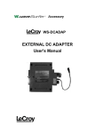
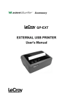
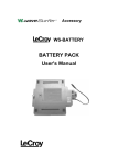
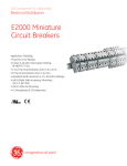
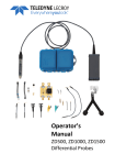
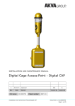
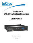
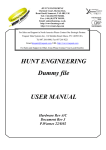
Accessory WS-BATT-CHRG BATTERY CHARGER User's Manual WaveSurfer is a trademark of LeCroy Corporation. Windows is a registered trademark or a trademark of Microsoft Corporation in the United States and other countries. BATTERY CHARGER User's Manual Foreword Thank you for purchasing LeCroy's BATTERY CHARGER. Before using this instrument, please read this manual thoroughly to gain a good understanding of it. After reading, please keep the manual in a safe place. This manual describes notes on use and basic usage of the BATTERY CHARGER. Notes Parts of the contents of this manual may be modified without prior notice for improvements in performance and functions. Reproduction or reprinting of the contents of this manual without prior permission from LeCroy is prohibited. If you have questions about the BATTERY CHARGER, please contact LeCroy Corporation. (Refer to the contact address given at the end of this manual.) Revision History June 2005: 1st edition KML050411 i A1-713500 WaveSurfer Accessary Checking the Packing Content On delivery of the BATTERY CHARGER, check each item. If any of the items are missing or there is any damage, immediately contact LeCroy or the sales office in charge. [Items to be present] • WS-BATT-CHRG (BATTERY CHARGER) .............................. 1 Accessories • CHARGE CONTROL cable ........................................................ 1 • Power cord .................................................................................... 1 • User's manual ............................................................................... 1 Sending Back for Repairs If the instrument is inoperable, send it back to LeCroy Corporation. (Refer to the contact address given at the end of this manual.) We will repair it without charge as long as it is under warranty. When sending back the instrument, explicitly describe the following: product name, serial number, description of the trouble, name/post/phone number of the contact person. ii Table of Contents Safety Requirements ....................................................................... 2 Product Disposal and Recycling...................................................... 6 Overview ......................................................................................... 7 Configuration ................................................................................... 7 Units ................................................................................................ 8 (a) BATTERY CHARGER................................................................ 8 (b) CHARGE CONTROL Cable....................................................... 9 (c) Front Panel ................................................................................ 9 (d) Rear Panel............................................................................... 10 Operating Procedures ....................................................................11 (a) Checking the Remaining Battery Charge Level of the BATTERY PACK ........................................................................................11 (b) Connecting the BATTERY PACK to the BATTERY CHARGER ............................................. 12 (c) Turning ON the POWER Switch on the BATTERY PACK ........ 14 (d) Turning ON the POWER Switch on the BATTERY CHARGER to Start Charging.......................................................................... 14 (e) Completing the Charging of the BATTERY PACK.................... 15 (f) Disconnecting the DC OUT Cable and CHARGE CONTROL Cable ....................................................................................... 15 Protective Functions ...................................................................... 16 Specifications ................................................................................ 17 (a) Product Specifications (1 of 2) ................................................. 17 (b) Product Specifications (2 of 2) ................................................. 18 (c) Certifications ............................................................................ 19 BATTERY CHARGER User's Manual Safety Requirements This section contains information and warnings that must be observed to keep the BATTERY CHARGER operating in a correct and safe condition. You are required to follow generally accepted safety procedures in addition to the safety precautions specified in this section. Safety Symbols & Terms The following symbols & terms may appear on the product and they alert you to important safety considerations. This symbol is used where caution is required. Refer to the accompanying information or documents in order to protect against personal injury or damage to the BATTERY CHARGER. This symbol warns of a potential risk of shock hazard. CAUTION The CAUTION sign indicates a potential hazard. It calls attention to a procedure, practice or condition which, if not followed, could possibly cause damage to equipment. If a CAUTION is indicated, do not proceed until its conditions are fully understood and met. WARNING The WARNING sign indicates a potential hazard. It calls attention to a procedure, practice or condition which, if not followed, could possibly cause bodily injury or death. If a WARNING is indicated, do not proceed until its conditions are fully understood and met. 2 WaveSurfer Accessory Operating Conditions Before using this product, ensure that its operating environment will be maintained within these parameters: Temperature: 5 to 40 oC Humidity: Altitude: Maximum relative humidity 80 % for temperatures up to 31 oC decreasing linearly to 50 % relative humidity at 40 oC. Up to 2,000 m The design of the BATTERY CHARGER has been verified to conform to the applicable safety standards (EN 61010-1:2001, UL 61010-1 2nd Edition and CAN/CSA C22.2 No.61010-1-04) per the following limits: Installation (Overvoltage) Category II (Line voltage in equipment and to wall outlet) Installation (Overvoltage) Category I (All mains isolated terminals) Pollution Degree 2 Protection Class I CAUTION To avoid personal injury or damage to the BATTERY CHARGER or the BATTERY PACK connected to it, review and comply with the following safety precautions. • Use only as intended. The BATTERY CHARGER is intended to be used only with the BATTERY PACK of LeCroy WaveSurfer series oscilloscopes. Do not connect the CHARGE CONTROL cable of the BATTERY CHARGER to any device other than the BATTERY PACK. Use of the BATTERY CHARGER and/or the equipment it is connected to in a manner not specified by the manufacturer(s) may impair the protection mechanisms. 3 BATTERY CHARGER User's Manual • Connect and disconnect properly. Do not disconnect the CHARGE CONTROL cable and/or the DC OUT cable of the BATTERY PACK while the BATTERY PACK is charged. Doing so may cause the product to malfunction corrupted. • Do not use in wet/damp or explosive atmospheres. • For indoor use only. The BATTERY CHARGER is intended for indoor use and should Be operated in a clean, dry, environment. • Do not operate with suspected failures. Do not use BATTERY CHARGER if any part is damaged. All maintenance should be referred to qualified service personnel. • Before mounting this product, always check the connecting procedures stated in this instruction manual. For safety reasons, make sure to turn off the power switch of the product before carrying out wiring of the connectors and cables. Also make sure to turn off the power button before connecting to the input power source. Turning on/off the power switch controls the on/off state of the output. • • Always use the supplied CHARGE CONTROL cable. If a cable other than the supplied CHARGE CONTROL cable, this may cause an electric shock, a fire, or a malfunction. • Stop use if the BATTERY PACK is not charged fully within the normal charging times. If the time required to charge the BATTERY PACK is significantly longer than the “normal” charging times shown in the specification section of the BATTERY PACK User’s Manual, this could indicate a problem with the BATTERY PACK or that the BATTERY PACK has exceeded the nominal battery life. If this occurs, please contact LeCroy sales or service office. • Connect the positive (+) and negative (-) terminals of the DC OUT cable of the optional BATTERY PACK of the oscilloscope to the positive (+) and negative (-) terminals of this product. The connector shape is so designed that the terminals cannot be 4 WaveSurfer Accessory connected with a combination other than that shown above. However, if the positive (+) and negative (-) terminals are connected incorrectly, this may cause an electric shock, a fire, or a malfunction. • Do not connect a cable or cord, such as AC cable other than that intended for operation stated in this instruction manual to the BATTERY or CHARGE CONTROL connector of this product. Doing so may cause an electric shock, a fire, or a malfunction. • Always use the proper 3-pin power cord suitable for the power voltage, which is supplied with this product. • If this product is not used, turn OFF the POWER switch of this product, hold the plug firmly, and disconnect the power cord from the outlet. Failure to do so may cause a malfunction, an electric shock, or a fire. • Always operate this product within a specified AC power voltage range. If the input current is excessive, the internal fuse is blown up to shutdown the power. At this time, to recover the BATTERY CHARGER, it is absolutely necessary to replace the internal fuse and make the adjustment. Ask LeCroy Corporation to repair the defective BATTERY CHARGER. • Keep product surfaces clean and dry. CLEANING The outside of the BATTERY CHARGER hardware should be cleaned with a soft cloth dampened with either deionized / distilled water or isopropyl alcohol. Allow the surface to dry completely before returning the instrument to service. USE AND MAINTENANCE The BATTERY CHARGER is a high quality, precision instrument. To maintain accuracy, mechanical shock should be avoided, as well as damage to the cables through excessive bending. All maintenance and component replacement should be referred to qualified personnel. 5 BATTERY CHARGER User's Manual Product Disposal and Recycling This electronic product is subject to disposal and recycling regulations that vary by country and region. Many countries prohibit the disposal of waste electronic equipment in standard waste receptacles. For more information about proper disposal and recycling of your LeCroy product, please visit www.lecroy.com/recycle. 6 WaveSurfer Accessory Overview This product is an optional unit that is specially designed for the oscilloscope and is intended to charge the optional BATTERY PACK. This instruction manual describes how to connect this product to the BATTERY PACK and how to charge the BATTERY PACK. Before using this product immediately after you have purchased it, thoroughly read this instruction manual to fully understand its contents. Configuration When charging the BATTERY PACK, the BATTERY PACK is connected to the BATTERY CHARGER (WS-BATT-CHRG) with the CHARGE CONTROL cable (supplied with the BATTERY CHARGER) and DC OUT cable as shown in Figure 1 below to charge the BATTERY PACK. The charge output is output from the BATTERY CHARGER to the DC OUT (indicated on the label) connector of the BATTERY PACK through the DC OUT cable during charging. Additionally, the control signal is input from the BATTERY CHARGER to the CHARGE CONTROL (indicated on the label) connector of the BATTERY CHARGER. DC OUT cable BATTERY PACK (WS-BATTERY) DC OUT BATTERY CHARGER (WS-BATT-CHRG) BATTERY CHARGE CONTROL CHARGE CONTROL CHARGE CONTROL cable Figure 1 Configuration for Charging of BATTERY PACK 7 BATTERY CHARGER User's Manual Units (a) BATTERY CHARGER Figure 2-1 shows the outside view of this product. Side panel Top panel Name Label Front panel Rear panel Side panel Rubber foot (4 locations) Unit: mm Figure 2-1 Outside View of BATTERY CHARGER 8 WaveSurfer Accessory (b) CHARGE CONTROL Cable The CHARGE CONTROL cable is supplied with the BATTERY CHARGER and it is connected to the BATTERY PACK during charging. Figure 2-2 shows the outside view of the CHARGE CONTROL cable. Unit: mm Figure 2-2 Outside View of CHARGE CONTROL Cable (c) Front Panel No. Name Description c BATTERY connector This connector is an output part of the BATTERY CHARGER. Connect the DC OUT cable of the BATTERY PACK to this connector for charging. Note) Do not connect any cable other than that of the BATTERY PACK. d CHARGE CONTROL connector This terminal is an input part of the BATTERY CHARGER. Connect the CHARGE CONTROL cable supplied with this product to this connector for charging. e POWER lamp This lamp is a power indication lamp of the BATTERY CHARGER. When turning ON the POWER switch on the rear, this lamp is lit in green. When turning OFF the POWER switch, the lamp goes off. f CHARGE lamp This lamp is a charge indication lamp of the BATTERY CHARGER. This lamp is lit in yellow during battery charging. When the battery charging is stopped, the lamp goes off. 9 BATTERY CHARGER User's Manual (d) Rear Panel ③ ① ② WEEE Label No. Name ④ Description c POWER POWER switch on the BATTERY CHARGER. I: POWER ON, O: POWER OFF When the POWER is turned ON, the POWER lamp on the front panel is lit in green. When the POWER is turned OFF, the POWER lamp on the front panel goes off. d ~LINE The power cord of the BATTERY CHARGER is connected to this connector. Power voltage: 90 to 264 Vrms Power frequency: 47 to 63 Hz e Name label LeCroy logo mark, logo mark of CE/UL standard, BATTERY CHARGER model name, power consumption, manufacture No., and manufacturer name are described on this name label. f WARNING WARNING indication stating that only authorized service engineers are allowed to open the product cover and to carry out the repair and calibration work. 10 WaveSurfer Accessory Operating Procedures Operate this product using the following procedures. (a) Checking the Remaining Battery Charge Level of the BATTERY PACK 1. An indication switch used to check the remaining battery charge level is provided at the upper portion of the name label of the BATTERY PACK. (See Figure 3-1.) Press this switch. 2. Five charge LEDs are arranged on the right of the indication switch. The remaining battery charge level is shown by lit or flashing LED lamps. NOTE 1 For details about description of charge LED lamp indications, see the section, “(C) Charge LED Lamp Indications”, on page 14 of the instruction manual for BATTERY PACK (WS-BATTERY), an optional unit of the oscilloscope. Charge LED lamps (Red ) Indication switch Figure 3-1 Remaining Charge Level Indication and Check 11 BATTERY CHARGER User's Manual (b) Connecting the BATTERY PACK to the BATTERY CHARGER Follow the steps below to connect the AC power cord, DC OUT cable, and CHARGE CONTROL cable. NOTE 2 Before starting the cable connections, always turn OFF the POWER switches on the BATTERY PACK and BATTERY CHARGER. 1. Connect the AC power cord to the rear panel of the BATTERY CHARGER (see Figure 3-2) and another connector of the AC power cord to a commercial power outlet. Figure 3-2 Connection of AC Power Cord 2. Next, insert the DC OUT cable of the BATTERY PACK into the BATTERY connector at the lower left portion of the front panel of the BATTERY CHARGER. (See Figure 3-3.) NOTE 3 At this time, connect the DC OUT cable while carefully checking the polarities, positive (+) and negative (−) terminals of the cable. + − Battery connector Figure 3-3 Connection of DC-OUT Cable 12 WaveSurfer Accessory 3. Connect the CHARGE CONTROL cable to the CHARGE CONTROL connector at the lower left portion of the front panel of the BATTERY CHARGER. (See Figs. 3-4a and 3-4b.) NOTE 4 Insert the connector (male) of the cable into the CHARGE CONTROL connector (female) firmly. Figure 3-4a Connection of DC OUT Cable Figure 3-4b Completion of Cable Connection 4. Connect the CHARGE CONTROL cable to the CHARGE CONTROL connector on the side panel of the BATTERY PACK. (See Figs. 3-5a and 3-5b.) NOTE 5 Insert the connector (male) of the cable into the CHARGE CONTROL connector (female) firmly. Figure 3-5a Connection of CHARGE CONTROL Cable 13 Figure 3-5b Completion of Cable Connection BATTERY CHARGER User's Manual (c) Turning ON the POWER Switch on the BATTERY PACK Make sure that the POWER switch is turned ON. If the POWER switch is OFF, always turn it ON. (See Figure 3-6.) POWER switch Black Green Figure 3-6 POWER Switch on BATTERY PACK (d) Turning ON the POWER Switch on the BATTERY CHARGER to Start Charging When pressing the [I] portion, the POWER switch on the BATTERY CHARGER is turned ON. On the contrary, when pressing the [O] portion, it is then turned OFF. (See Figure 3-7.) Figure 3-7 POWER Switch on BATTERY CHARGER The BATTERY CHARGER now begins to charge the BATTERY PACK. The POWER lamp on the front panel is lit in green and the CHARGE lamp is lit in yellow during charging. The remaining battery charge level is indicated by the charge LED lamps (five LED lamps are lit in red) on the BATTERY PACK. 14 WaveSurfer Accessory (For details, see the section, "Charge LED Lamp Indications", on page 15 of the instruction manual for BATTERY PACK.) If the remaining battery charge level becomes 80% or more, five charge LED lamps are lit in red. Charge the BATTERY PACK until all five LED lamps are lit in red. When the charging is completed, the CHARGE lamp goes off and five charge LED lamps (red) also go off. NOTE 6 It is not necessary to set the charging conditions and charging time. The reference charging time until the BATTERY PACK is fully charged is approximately 3 hrs. It takes a relatively short time to charge the BATTERY PACK to a remaining battery charge level of 80%. (e) Completing the Charging of the BATTERY PACK When the CHARGE lamp on the BATTERY CHARGER goes off and the charging is completed, turn OFF the POWER switch on the BATTERY CHARGER. (f) Disconnecting the DC OUT Cable and CHARGE CONTROL Cable For details about how to connect the BATTERY PACK to the oscilloscope, how to operate the oscilloscope by the DC power, and how to read the remaining battery charge level indications, see the instruction manual for BATTERY PACK. 15 BATTERY CHARGER User's Manual Protective Functions Protective circuits for electrical connection and temperature conditions are provided on this product. Table 4 describes the protective functions and symptoms. If any symptom stated in Table 4 occurs, contact LeCroy Corporation. Table 4 Protective Functions and Corrective Actions <Protective function> Description and corrective action Charge output over-current protection If the output current becomes excessive for some reason, the output fuse is blown up. To recover the BATTERY CHARGER, it is necessary to replace the output fuse and make the adjustment. Contact the service department of LeCroy Corporation. Charge output over-voltage protection If the output voltage becomes excessive for some reason, the output is stopped. To recover the BATTERY CHARGER, it is necessary to reset the over-voltage status and make the adjustment. Contact the service department of LeCroy Corporation. Over-heat protection If the BATTERY CHARGER is operated at a temperature exceeding the specified operating temperature range, the thermal fuse is blown up to stop the output. To recover the BATTERY CHARGER, it is necessary to replace the thermal fuse and make the adjustment. Contact the service department of LeCroy Corporation. 16 WaveSurfer Accessory Specifications (a) Product Specifications (1 of 2) Item Specifications <Electrical specifications> Method Switching Charging method Constant current and voltage Output voltage 25.2 Vdc±2 % Output current 5.0 A ± 7 % (During charging) 0.2 A ± 58 % (During pre-charging) Power voltage Single-phase, 90 to 264 Vrms, sine wave Power frequency 47 Hz to 63 Hz Power consumption 200 VA or less Insulation resistance 10 MΩ or more (Between power input and BATTERY connector and between power input and CHARGE CONTROL connector, at DC500 V.) Withstanding voltage 2k Vac (1 min., 50/60 Hz, between power input and chassis) 3k Vac (1 min., 50/60 Hz, between power input and BATTERY connector and between power input and CHARGE CONTROL connector) *1. The appearance and specifications are subject to change without prior notice. *2. This product has passed the conformity inspection of the electric product safety laws. 17 BATTERY CHARGER User's Manual (b) Product Specifications (2 of 2) Item Specifications <Environmental specifications> Temperature Humidity (No dew condensation) Operation: +5 °C to +40 °C Storage (non-operating): −20 °C to +60 °C Operating: Maximum relative humidity (RH) 80 % for temperatures up to 31 oC decreasing linearly to 50 % RH at 40 oC. Storage (non-operating): 5 % to 95 % RH. Upper limit derates to 50 % RH above 40 °C. Operating: Up to 6,562 ft (2,000 m) Altitude Storage (non-operating): Up to 40,000 ft (12,192 m) <General specifications> Outside dimensions 240 (W) × 170 (D) × 65 (H) [mm] Tolerance: 2 [mm] Length of CHARGE CONTROL cable 0.60 [m] ± 0.05 [m] Length of power cord 2.0 [m] ± 0.1 [m] Weight Approx. 1.3 kg *1. The appearance and specifications are subject to change without prior notice. 18 WaveSurfer Accessory (c) Certifications Meets intent of the European Council Directives 73/23/EEC for product safety and 89/336/EEC for electromagnetic compatibility. This declaration is based upon compliance of the Battery Charger to the following standards: EC Declaration EN 61326: 1997 +A3:2003 EMC requirements for of Conformity electrical equipment for measurement, control, and laboratory use. Emissions: EN 55022: 1994+A1:1995+A2:1997 Radiated & Conducted Emissions (Class A) EN 61000-4-3:2000 Harmonic Current Emissions Immunity: EN 61000-4-2:1999 Electrostatic discharge (+4kV contact discharge; +8kV air discharge) EN 61000-4-3: 2002+A1:2003 RF Radiated Fields (3V/m, 80 MHz to 1 GHz, 80% amplitude modulated) EN 61000-4-4: 2004 Electrical Fast Transient/Burst (1 kV on AC mains) EN 61000-4-5: 1995+A1:2001 Surge (1 kV differential mode, 2 kV common mode) EN 61000-4-6: 1996+A1:2001 RF Conducted Field (3 V, 150 kHz to 80 MHz, amplitude modulated with 1kHz sine wave) EN 61000-4-11: 2004 Mains Dips and Interruptions (100% interruption for 1 full AC cycle) EN 61010-1: 2001 Safety requirements for electrical equipment for measurement control and laboratory use With the following limits: Installation (Overvoltage) Category II (Line voltage in equipment and to wall outlet) Installation (Overvoltage) Category I (All mains isolated terminals) Pollution Degree 2 Protection Class I 19 BATTERY CHARGER User's Manual UL and cUL Listed - Conforms to UL 61010-1, 2nd Edition and CAN/CSA C22.2 No. 61010-1-04 20 LeCroy Corporation 700 Chestnut Ridge Road Chestnut Ridge, NY 10977–6499 Tel: (845) 578 6020, Fax: (845) 578 5985 Internet: www.lecroy.com © 2004 by LeCroy Corporation. All rights reserved. LeCroy, ActiveDSO, ProBus, JitterTrack, WavePro, WaveMaster, WaveSurfer, and Waverunner are registered trademarks of LeCroy Corporation. Information in this publication supersedes all earlier versions. Specifications subject to change without notice. WaveSurfer Accessory WS-BATT- CHRG