1
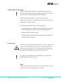
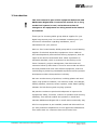
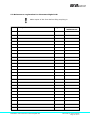
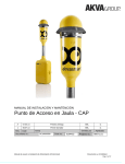
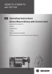
INSTALLATION AND MAINTENANCE MANUAL
Digital Cage Access Point - Digital CAP
A
04.02.15
Rev
Date
Part name:
Approved
Issued
DC10000790
Project number:
Installation and maintenance Manual Digital CAP
EBL
IL
Issued by
Approved
88073-01
Document no. DC10000790
Page 1 av 20
For a thorough introduction of Your AKVA product, we ask that
all users read this entire manual. If questions occur, contact us!
The information in this document is subject to change without
notice and should not be construed as a commitment by
AKVA group ASA.
AKVA group ASA assumes no responsibility for any errors
that may appear in this document.
In no event shall AKVA group ASA be liable for incidental or
consequential damages arising from use of this document or
of the software and hardware described in this document.
We reserve all rights in this document and in the information
contained therein. Reproduction, use or disclosure to third
parties without express authority is strictly forbidden.
This document can also be read and downloaded from our web
site, see www.akvagroup.com/products/user-manuals
© 2015 AKVA group ASA (NO)
AKVA group ASA
Installation and maintenance Manual Digital CAP
Document no. DC10000790
Page 2 av 20
Table of contents
1
Safety ........................................................................................................4
1.1
Safety symbols used in the manual ................................................................. 4
1.2
Receiving a new product ............................................................................... 5
1.3
Plug-caps .................................................................................................... 5
1.4
Connection points and cable .......................................................................... 6
1.5
Installation .................................................................................................. 6
1.6
Maintenance ................................................................................................ 6
2
Introduction ..............................................................................................7
2.1
Contact information ...................................................................................... 8
3
Information ...............................................................................................9
3.1
Specifications for Akvasmart Digital CAP......................................................... 10
4
Installation ..............................................................................................11
4.1
Before taking the Digital CAP to the cage ...................................................... 11
4.2
Attach extension pole to the connection box ................................................... 14
4.3
Attach the Digital CAP top ............................................................................ 15
5
Maintenance ............................................................................................16
5.1
Cleaning ................................................................................................... 16
5.2
Tighten up ................................................................................................ 16
5.3
Maintenance registration for Akvasmart Digital CAP ........................................ 17
Appendix A - Index ..........................................................................................18
Appendix B - Deviation form ............................................................................19
Appendix C - Notes ..........................................................................................20
Installation and maintenance Manual Digital CAP
Document no. DC10000790
Page 3 av 20
1 Safety
Safety for the users of our equipment is top focus when AKVA
group ASA develop new products and product manuals.
We therefor strongly recommend that everyone that use the
equipment, all that perform any type of repairs, service or other
maintenance to the product, and all that work in areas where the
product is installed read this entire manual and at least this
safety chapter.
This recommendation is based on both personnel safety as well
as the desire to keep all products in order as long as expected,
and to avoid any damages risked if the safety instructions from
this manual are not followed.
1.1 Safety symbols used in the manual
The following symbols are used in this manual:
Information
Show caution, danger of damaging equipment and mild
injuries to personnel
Show caution, damages to personnel may occur
1.1.1 Other symbols used in the manual
See chapter or page for more information or further instructions.
Installation and maintenance Manual Digital CAP
Document no. DC10000790
Page 4 av 20
1.2 Receiving a new product
Always check that the delivery is complete according to the
service note. If the order is not complete or if any other errors
are discovered, contact AKVA group immediately.
AKVA group ASA provides a 1 year warranty covering
manufacturer’s defects. The warranty is effective upon date of
shipment to original recipient.
The following are reasons for a void of warranty:
- poor treatment of the system due to negligence of preventive
recommendations and other instructions in this manual
- improper usage of power sources
- the Digital CAP is opened without express written consent of
an AKVA group3 employee.
1.3 Plug-caps
Keep the plug caps and their attachments in order, in place and
intact to avoid damages and to assure a long lasting product.
If plug caps are damaged or are not being used as described in
this manual, the warranty may expire or be reduced.
If a plug cap is loosened from the equipment, contact AKVA
immediately to order a new cap.
Hint!
Keep a backup storage of plug caps to make sure that all of the
products connections will always be protected
Installation and maintenance Manual Digital CAP
Document no. DC10000790
Page 5 av 20
1.4 Connection points and cable
Cables and connection points need to be treated with great
caution, to avoid the risk of reducing the product’s operating
time.
Camera and sensor cables does not bear any twirls, twists
or sharp bends
1.5 Installation
Cages are exposed to a lot of weather and winds, creating
movements in the cage and thus the Digital CAP cage rail
fastening points. Therefore there is a risk that bolts and nuts
are loosened in the fastening brackets. Therefore, it is important
to tighten up all bolts regularly.
1.6 Maintenance
See maintenance instructions in chapter 5 to ensure a long
lasting product.
Installation and maintenance Manual Digital CAP
Document no. DC10000790
Page 6 av 20
2 Introduction
This user manual is part of the equipment delivered with
AKVAsmart Digital CAP. Preserve the manual for as long
as the feed system is used, and make sure that all
changes to the equipment are being noted in the back of
the manual.
Thank you for choosing AKVA group ASA as supplier for your
digital cage access point. Do not hesitate contacting us if you
need more information regarding installation, use or
maintenance for your product.
With our four house brands, AKVA group ASA is a world leading
supplier of technical aquaculture equipment. Since 1980 we
have developed and produced fish farming equipment, both for
cages at sea and for land based sites. AKVA represents an
industrial standard, which is presumed to be the key to the
future. Research, project management, fast deliveries and
customer follow-up have been in focus to ensure that we deliver
the best possible and most cost efficient equipment, and thus
contributing to preserving sustainable aquaculture and a positive
development within the aquaculture industry.
We have a wide variety of products, including plastic and steel
cages, high pressure washers, net cleaners, boats, feed barges,
feeding systems, cameras, sensor systems, under water lighting,
software for fish farming and recycling systems.
We practice continuous product development to improve the
equipment’s safety, functions, manner of operation and working
reliability. This manual enables the operator to install and
maintain AKVAsmart Digital CAP in a safe and economically way.
All of our equipment is pre-installed, tested and delivered from
our own production department or from approved collaborators.
This means that our customers have total control over
Installation and maintenance Manual Digital CAP
Document no. DC10000790
Page 7 av 20
components to choose from, grouping collocation, testing and
deliveries. Our production staff consists of people with great
expertise and enthusiasm to produce the best possible products
for our customers. Having our own production site gives our
customers excellent service in case something should go wrong,
or if any assistance is needed. We hold most of the parts for
our products in stock, and our service staff is available on the
telephone or on location in order to assist you if necessary.
This entire manual, and especially the safety chapter
must be read and understood before commencing any
work on the Digital CAP
Before any work is done with the Digital CAP, we recommend
that all users are properly trained by AKVA group ASA. All users
need to get to know this manual and its contents, and perform
procedures for installation and maintenance as described here to
ensure reliable operations and a long lasting product. This
manual answers most day to day questions and gives a thorough
description of how to install and maintain the Digital CAP.
2.1 Contact information
AKVA group ASA - Bryne, Norge (Head office)
Nordlysveien 4
PO. Box 271
4340 Bryne
tlf. 51 77 85 00, fax. 51 77 85 01
Support Hardware og AKVAconnect
tlf. 51 77 85 03
[email protected]
Support Fishtalk
tlf. 73 84 28 20
[email protected]
Installation and maintenance Manual Digital CAP
Document no. DC10000790
Page 8 av 20
3 Information
Akvasmart Digital CAP (Cage Access Point) is a wireless
access point for both under water cameras and winch. With
transmission of up to 6 parallel video channels, this system
will fit any fish farm.
One under water video camera may be connected to each unit,
in addition to an integrated surface surveillance camera
(mounted in the Digital CAP top).
The new Digital CAP has a powerful transmitter, external channel
selector, 360 degree adjustable surface camera and directional
antenna.
Video images are transmitted wireless from each cage edge to
the main base.
Power transfer via 230V hard wired electricity from the feed
barge. For short term backup, a 60Ah battery may be used.
Battery size (l x b x h): 270 x 175 x 225mm.
Item numbers for battery options:
- Battery Gel 12V/60Ah: 0101887
- Battery 12V/80Ah: 10191
The Digital CAP house is made of aluminum, polycarbonate
(PC)/Lexan and stainless steel. All is water proof and sprout
safe.
All cables are connected inside the connection box.
Installation and maintenance Manual Digital CAP
Document no. DC10000790
Page 9 av 20
3.1 Specifications for Akvasmart Digital CAP
Built-in surface camera
Resolution
Light sensitivity
Angle of view
Frequency - Ethernet
Power Supply
Power Consumption
Materials
Size - width x height
Weight
Ethernet
1 pcs.
704x576
1.0Lux (Colour) - 0.3Lux (B/W)
360⁰ Pan/Tilt 12x700m
5.8 GHz Cambium *
12V/230VAC**
1-6A
Aluminum/PC/Stainless Steel
Ø280 x 770mm (Ø10.9” x 30.3”)
12.5kg
2 pcs. Phoenix contact 8 pin RJ45 w/clips
Underwater Camera connections
1 pcs. Amphenol 7 pins female
Camera Winch connections
1 pcs. Amphenol 7 pins female
Power connections
1 psc. Amphenol 4 pins female
* Frequency may vary from country to country
** Via AC adapter (extra)
Installation and maintenance Manual Digital CAP
Document no. DC10000790
Page 10 av 20
4 Installation
Safety garments, for instance safety vest, must be used
during labour at or by cages
Digital CAP top contains a camera and must therefore be
treated very carefully
Handle all equipment and parts with care, and make sure
that none of them fall into the sea during the installation
process
Fasten connection box to a cage pole first, then attach the top of
the Digital CAP to the connection box, for easier handling during
the installation
Different types of cages have different types of poles. Fasten the
Digital CAP using brackets that fits the specific cage pole
4.1 Before taking the Digital CAP to the cage
The rails for fastening brackets should be attached to the back
side of the connection box when delivered. If this is not done,
both rails must be attached before taking the Digital CAP to the
cage.
Also fasten the brackets to the rails before
taking the Digital CAP to the cage.
The back side of the Digital CAP
connection box have 2 x 3 holes
(3 upper and 3 lower holes)
for fastening the rails ->
Necessary equipment:
- everything from the delivery (check service note)
- two open end spanners (wrenches)
Installation and maintenance Manual Digital CAP
Document no. DC10000790
Page 11 av 20
4.1.1 Single poles
This method goes for Polarcirkel plastic cage rails as well as
single pole steel cage rails.
Procedure:
1 Before taking the Digital CAP to the cage edge, the following
must be performed:
a Attach the upper rail to the back of the Digital CAP
connection box firstly through the middle hole
b Thread the two brackets parts in to the rail
Make sure that the brackets are
placed correctly in the rail, according
to the illustration to the left
c Fasten the rail end bolts
d Repeat this procedure as the lower rail is
attached to the Digital CAP connection box
2 Bring connection box, Digital CAP top, fastening bolts and
necessary equipment from page 10 to the cage edge where
the Digital CAP is being installed
Digital CAP top contains a camera and must therefore
be treated very carefully
3 Place the Digital CAP connection
box next to the desired cage
pole
4 Place the brackets around the
pole and fasten them with
bolts and nuts, tighten well
to make sure that they sit
properly when the cage moves.
Installation and maintenance Manual Digital CAP
Document no. DC10000790
Page 12 av 20
4.1.2 Double poles
AKVA groups Wavemaster steel cages have double rail poles,
and requires a different kind of fastening than for single poles.
Procedure:
1 Before taking the Digital CAP to the cage edge, the following
must be performed:
a Attach the upper rail to the back of the Digital CAP
connection box firstly through the middle hole
b Thread two bracket parts in to each side of the rail
Make sure that the brackets are
placed correctly in the rail, according
to the illustration to the left
c Fasten the rail end bolts
d Repeat this procedure as the lower rail is
attached to the Digital CAP connection
box
2 Bring connection box, Digital CAP top, fastening bolts and
necessary equipment from page 10 to the cage edge where
the Digital CAP is being installed
Digital CAP top contains a camera and must therefore
be treated very carefully
3 Place the CAP connection box
next to the desired cage poles
4 Place the brackets around the poles
and fasten them with bolts and nuts, tighten well to make
sure that they sit properly when the
cage moves.
Installation and maintenance Manual Digital CAP
Document no. DC10000790
Page 13 av 20
4.2 Attach extension pole to the connection box
When the connection box is attached properly to the cage
pole(s), and before the Digital CAP top can be attached, the pole
in between these parts must be fastened to the connection box.
Necessary equipment
- extension pole
- 3mm Umbraco key
- 4 x M6 bolts
Procedure
1 Open the connection box
2 Tread the pole in the top opening of the connection box
3 Fasten all four bolts (marked with red in the illustration below)
to attach the extension pole to the connection box
4 Close the connection box.
Installation and maintenance Manual Digital CAP
Document no. DC10000790
Page 14 av 20
4.3 Attach the Digital CAP top
When the connection box is attached properly to the cage
pole(s), and the extension pole is in place, the Digital CAP top
may be attached.
Necessary equipment
- two M6 set screws
- 3mm Unbraco-key
Procedure:
1 Tread the Digital CAP on to the extension pole
2 Align the signal symbol so that it points directly towards the
barge (or the signal receiver)
3 Fasten with the set screws, use the 3mm Unbraco key to
fasten the screws properly.
Installation and maintenance Manual Digital CAP
Document no. DC10000790
Page 15 av 20
5 Maintenance
Safety garments, for instance safety vest, must be used
during labour at or by cages
5.1 Cleaning
Clean the inside of the connection box once a month, use a soft
cloth, warm water and a mild detergent. Wipe off all excessive
water inside, remember to wipe the cables as well.
Hose the Digital CAP with fresh water once a week. Always use
normal water pressure, no high pressure cleaner! Spray siliconc
grease to fastening bits, hinges and locks.
Make sure that the Digital CAP connection box is properly
closed before hosing it down
5.2 Tighten up
Tighten up all fastening bits to avoid that the Digital CAP falls off
the cage end after movements in the sea and cage. Check and
tighten all fastening bolts at least once a month, and more often
during bad weather seasons and periods.
Weekly maintenance: outside cleaning, spray fastening bits,
hinges and locks with grease
Monthly maintenance: inside cleaning, check and tighten all
fastening bolts, check cables and cable connections
All maintenance tasks must be performed more often during
stormy seasons and periods
Installation and maintenance Manual Digital CAP
Document no. DC10000790
Page 16 av 20
5.3 Maintenance registration for Akvasmart Digital CAP
Make copies of this form before filling anything in
Date
Task performed
Installation and maintenance Manual Digital CAP
Signature
Date for next
maintenance
Document no. DC10000790
Page 17 av 20
Appendix A - Index
A
P
antenna 9
plastic cage 12
plug caps 5
B
power transfer 9
bolts 6, 12-14, 16
procedure 12-15
bracket 6, 11-3
C
cable 6, 9, 16
cable connections 16
cage pole 11-13, 15
camera 6, 9-13
channel selector 9
cleaning 16
connection box 9, 11-16
D
damages 4, 5
S
safety 4
safety garments 11, 16
service note 5, 11
signal symbol 15
siliconc grease 16
surface camera 9
symbols 4
T
tighten 6, 12, 13, 16
transmitter 9
F
fresh water 16
V
video channels 9
I
information 4, 9
W
installation 6, 11
warranty 5
weather 6, 16
M
wireless 9
maintenance 6, 16
Installation and maintenance Manual Digital CAP
Document no. DC10000790
Page 18 av 20
Appendix B - Deviation form
Make copies of this form before filling anything in.
Deviation control nr.:
Unit:
Producer:
Prod.no.:
Purchase year:
Deviation description:
Follow up proposition:
Date and signature, declarer:
Follow up directed:
Status:
New action for deviation no.:
Date and signature, follow up:
Installation and maintenance Manual Digital CAP
Document no. DC10000790
Page 19 av 20
av 20
Appendix C - Notes
Installation and maintenance Manual Digital CAP
Document no. DC10000790
Page 20 av 20