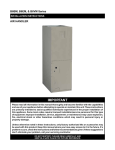
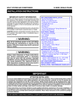
1
B6BX SERIES AIR HANDLER
Installation Instructions
IMPORTANT
Please read all information in this manual thoroughly and become familiar with the capabilities
and use of your appliance before attempting to operate or maintain this unit. These instructions
are primarily intended to assist qualified individuals experienced in the proper installation of
this appliance. Some local codes require licensed installation/service personnel for this type
of equipment. Improper installation, service, adjustment, or maintenance may cause explosion,
fire, electrical shock or other hazardous conditions which may result in personal injury or
property damage.
Unless otherwise noted in these instructions, only factory authorized kits or accessories may
be used with this product. Keep this manual where you have easy access to it in the future. If a
problem occurs, check the instructions and follow recommendations given. If these suggestions
don’t eliminate your problem, call your servicing contractor.
DO NOT DESTROY. PLEASE READ CAREFULLY AND
KEEP IN A SAFE PLACE FOR FUTURE REFERENCE.
TABLE OF CONTENTS
Important Safety Information.....................................3
Requirements & Codes...............................................3
General Information....................................................4
Before You Install this Unit..........................................4
Locating the Air Handler.............................................4
Minimum Clearances..................................................4
Operation of Air Handler During Construction............4
Installation in a Garage..............................................5
Plenums & Air Ducts..................................................5
Unconditioned Spaces............................................5
Air Filters.................................................................5
Acoustical Duct Work..............................................5
Startup & Adjustments.............................................13
Before You Start the Unit..........................................13
Refrigerant Charging................................................14
Air Circulation...........................................................14
Running the Blower Continuously......................... 14
Selecting Continuous Low Spd Fan Operation..... 14
Turning the Blower Off..........................................14
System Cooling.....................................................14
System Heating.....................................................14
Blower Configurations..............................................14
3-Speed Units.......................................................14
5-Speed Units.......................................................14
Unit Maintenance.......................................................15
Troubleshooting.........................................................15
Air Handler Installation...............................................6
Packaging Removal....................................................6
Mounting Applications................................................6
Upflow Installations....................................................6
Downflow Installations................................................6
Horizontal Installations...............................................6
Horizontal Left Installations.....................................7
Horizontal Right Installations..................................7
Refrigerant Line Connections.....................................8
Orifice removal & Installation..................................8
Connecting the Linsets...........................................9
Condensate Drainage .............................................10
Figures & Tables........................................................16
Figure 12. B6BX Physical Dimensions..................16
Figure 13. B6BX Components..............................17
Electrical Connections..............................................11
Pre-Electrical Checklist............................................11
Line Voltage..............................................................11
Grounding................................................................11
Thermostat Connections..........................................11
Control Board...........................................................12
Twinning................................................................12
Heater Kits...............................................................12
Electronic Air Cleaner..............................................12
Humidifier.................................................................12
Installation / Performance Checklist........................24
2
Airflow Data..............................................................18
Table 3. B6BX Blower Performance Data..............18
Electrical Data & Diagrams......................................19
Table 4. B6BX MCA & MOP Data.........................19
Table 5. Control Board Operation..........................20
Table 6. Control Board Settings.............................20
Figure 14. W.D. with PSC Motor............................21
Figure 15. W.D. with ECM Motor...........................22
Important SAFETY INFORMATION
INSTALLER: Please read all instructions before servicing
this equipment. Pay attention to all safety warnings and
any other special notes highlighted in the manual. Safety
markings are used frequently throughout this manual to
designate a degree or level of seriousness and should not
be ignored. WARNING indicates a potentially hazardous
situation that if not avoided, could result in personal injury
or death. CAUTION indicates a potentially hazardous
situation that if not avoided, may result in minor or moderate
injury or property damage.
WARNING:
ELECTRICAL SHOCK, FIRE OR EXPLOSION
HAZARD
Failure to follow safety warnings exactly could
result in serious injury or property damage.
Improper servicing could result in dangerous
operation, serious injury, death or property
damage.
• Before servicing, disconnect all electrical power
to air handler.
• When servicing controls, label all wires prior
to disconnecting. Reconnect wires correctly.
• Verify proper operation after servicing.
WARNING:
NITROGEN
HEALTH
1
FLAMMABILITY
0
REACTIVITY
0
0 Minimal Hazard
1 Slight Hazard
B6 Series Air Handlers leave the factory with
a nitrogen holding charge. Use caution when
preparing coils for field connections. If repairs
make it necessary for evacuation and charging,
it should only be attempted by qualified,
trained personnel thoroughly familiar with this
equipment. Some local codes require licensed
installation service personnel to service this
type of equipment. Under no circumstances
should the equipment owner attempt to install
and/or service this equipment. Failure to comply
with this warning could result in equipment
damage, personal injury, or death.
Requirements & Codes
WARNING:
This unit must be installed in accordance with
instructions outlined in this manual during
the installation, service, and operation of
this unit. Unqualified individuals should not
attempt to interpret these instructions or
install this equipment. Failure to follow safety
recommendations could result in possible
damage to the equipment, serious personal
injury or death.
• The installer must comply with all local codes and
regulations which govern the installation of this type
of equipment. Local codes and regulations take
precedence over any recommendations contained in
these instructions. Consult local building codes for
special installation requirements.
• This equipment contains nitrogen gas. Installation or
servicing should only be performed by qualified trained
personnel thoroughly familiar with this type equipment.
• All electrical wiring must be completed in accordance
with local, state and international codes and regulations.
• Installation of equipment may require brazing operations.
Installer must comply with safety codes and wear
appropriate safety equipment (safety glasses, work
gloves, fire extinguisher, etc.) when performing brazing
operations.
• Install this unit only in a location and position as specified
on pages 4 & 5. This unit is designed only for Indoor
installations and should be located with consideration
of minimizing the length of the supply and return ducts.
See Table 4 (page 18) and the rating plate for proper
circulating airflow data.
• Follow all precautions in the literature, on tags, and
on labels provided with the equipment. Read and
thoroughly understand the instructions provided with
the equipment prior to performing the installation and
operational checkout of the equipment.
• This air handler may be used for temporary heating
of buildings or structures under construction. See the
guidelines listed on page 4.
• Air handler installations in a residential garage must be
installed as specified on page 5.
3
GENERAL INFORMATION
This appliance has been tested for capacity and efficiency
in accordance with AHRI 210/240 Standards and will
provide many years of safe and dependable comfort,
providing it is properly installed and maintained. Abuse,
improper use, and/or improper maintenance can shorten
the life of the appliance and create unsafe hazards. Please
read all instructions before installing the unit.
Before You Install this Unit
√This equipment is securely packaged at the time of
shipment and upon arrival should be carefully inspected
for damage prior to installing the equipment at the job
site. Claims for damage (apparent or concealed) should
be filed immediately with the carrier.
√ The cooling load of the area to be conditioned must be
calculated and a system of the proper capacity selected.
It is recommended that the area to be conditioned be
completely insulated and vapor sealed.
√ Check the electrical supply and verify the power supply
is adequate for unit operation.The system must be wired
and provided with circuit protection in accordance with
local building codes. If there is any question concerning
the power supply, contact the local power company.
√ Verify the duct system is appropriate for the air handler
being installed. Please note that when replacing an
existing system with lower air-flow, the duct system
may require modification.
Locating the Air Handler
• Survey the job site to determine the best location for
mounting the unit. Consideration should be given to
availability of electric power, service access, and noise.
• The dimensions of the room or alcove must be able
to accommodate the overall size of the unit and the
installation clearances listed in Figure 1. Physical
dimensions for this air handler are also shown in Figure
12 (page 16).
• The air handler should be set into position before routing
the refrigerant tubing.
REAR
0 cm / in.
LEFT SIDE
0 cm / in.
RIGHT SIDE
0 cm / in.
FRONT
† See Note
†NOTE:
Alcove Installations - Allow 61 cm (24 in.) minimum clearance
from front of unit to nearest wall or partition for servicing.
Recommended clearance is 91 cm (36 in.).
Figure 1. Minimum Unit Clearances
4
Minimum Clearances
• This appliance must be installed in accordance with
clearances listed in Figure 1. The air handler must be
installed with ample clearance for easy access to the air
filter, blower assembly, heater assembly and controls.
Applicable building codes may require additional
clearance to equipment. Refer to applicable building
codes for details.
• Static pressure drop through louvered openings and
through return air plenums should be considered in
the overall duct design in the determination of the total
external static pressure.
Operation of Air Handler During Construction
CAUTION:
Failure to follow these instructions will void the
factory warranty and may significantly reduce
the life or the performance of the air handler,
and/or result in other unsafe conditions. It is
the responsibility of the installing contractor
to insure these provisions are met.
Operating an air handler in a construction environment
can cause the appliance a variety of problems. Proper
use of commercial portable space heating equipment
during construction is recommended. This air handler
may be used during construction if it is not in violation of
any applicable codes and the following criteria are met:
• The installation must meet all applicable codes and
be permanently installed according to the instructions
supplied with the air handler including electrical supply
and duct work.
• The air handler must be controlled by a properly
installed thermostat that complies with the current
provisions of national and local electrical codes.
Thermostat connections must be made in accordance
with instructions supplied with the air handler and
thermostat. See page 11.
• The installation must include a properly installed filter in
the return air system with no by-pass air. The filter must
be inspected frequently and replaced when necessary.
• Return air must be supplied unrestricted and located
such that dust and gases from construction activity are
not introduced into the circulating air system.
• Before occupying the structure: The filter must be
replaced or cleaned, the duct work must be inspected
and cleaned of any construction debris, and the air
handler must be cleaned and/or repaired if found to
be dirty, damaged, or malfunctioning in any way by
a qualified HVAC technician. The air handler shall be
inspected and approved by applicable local authority
even if this requires redundant inspections.
• The serial number for the air handler used during
construction must be submitted in writing (fax and
email also acceptable). This information will be used to
track the long-term affects of air handler usage during
construction. Proof of this submittal shall be available for
the final inspection of the air handler prior to occupancy.
Installation in a Garage
WARNING:
Do not place combustible materials on or against
the cabinet. Do not place flammable materials,
(gasoline, paint thinners, etc.) or any other
flammable vapors and liquids, in the vicinity
of the air handler.
The B6 Series air handler may be installed in a residential
garage with the provision that the unit must be located or
protected to prevent physical damage by vehicles.
Plenums & Air Ducts
WARNING:
All return ducts must be secured to the air
handler using appropriate methods. All return
ducts must be adequately sealed. When return
air is provided through the bottom of the unit,
the joint between the air handler and the return
air plenum must be air tight.
Return air and circulating air ducts must not be
connected to any other heat producing device
such as a fireplace insert, stove, etc. This may
result in fire, explosion, carbon monoxide
poisoning, personal injury, or property damage.
• Supply and return air must be delivered to the air handler
by duct(s) secured to the air handler casing, running
full size and without interruption.
• This unit is designed only for use with a return and supply
duct. The return air duct must have the same free area
as the opening provided on the air handler. The ducts
should be appropriately sized to the capacity of the air
handler to ensure its proper airflow rating. Table 3 (page
18) contains the maximum airflow data listed by model.
• Use transition fittings if the supply and/or return air
openings of the unit do not match the duct openings.
These transitions should be dimensioned in accordance
with standard practice as specified in the ASHRAE
recommendations for duct transitions.
• Flexible connectors may be used between the unit
and the ductwork to prevent transmission of vibration
from the unit to the structure. If electric heater kits are
installed, heat resistant material must be used for the
flexible connector at the supply air end of the unit.
• Seal all connections and joints with industrial grade
sealing tape or liquid sealant. Requirements for sealing
ductwork vary from region to region. Consult with local
codes for specific requirements.
Unconditioned Spaces
All duct work passing through unconditioned space must
be properly insulated to minimize duct losses and prevent
condensation. Use insulation with an outer vapor barrier.
Refer to local codes for insulation material requirements.
Air Filters
B6 Series Air Handlers are not supplied with an air filter
when shipped from the factory. The installer must provide
a high velocity filter that is appropriately sized to the return
air duct opening or filter rack located in the bottom of the
unit. Accessing the filter does not require tools and can
be removed from the front of the unit by removing the filter
door. See Unit Maintenance (page 15) for filter sizes and
installation information.
WARNING:
Never operate the air handler without a filter
or with doors removed. Dust and lint can build
up on internal components, resulting in loss of
efficiency, equipment damage, and possible fire.
Acoustical Duct Work
• Certain installations may require the use of acoustical
lining inside the supply duct work. Acoustical insulation
must be in accordance with all national and local codes
for duct liners. Duct lining must be UL classified batts or
blankets with a fire hazard classification of FHC-25/50
or less.
• Fiber duct work may be used in place of internal duct
liners if the fiber duct work is in accordance with all
national and local codes. Fibrous duct work and internal
acoustical lining must be NFPA Class 1 air ducts when
tested per UL Standard 181 for Class 1 ducts.
• Damping ducts, flexible vibration isolators, or pleated
media-style filters on the return air inlet of the air
handler may be used to reduce the transmission of
equipment noise eminating from the air handler. These
treatments can produce a quieter installation, particularly
in the heated space. However, they can increase the
pressure drop in the duct system. Care must be taken
to maintain the proper maximum pressure rise across
the air handler, temperature rise and flow rate. This
may mean increasing the duct size and/or reducing the
blower speed. These treatments must be constructed
and installed in accordance with all national and local
codes. For best sound performance, be sure to install all
the needed gaskets and grommets around penetrations
into the air handler, such as for electrical wiring.
5
Air handler INSTALLATION
The B6 Series Air Handler is shipped ready for vertical
upflow installation and is approved for attic, basement,
alcove/closet or crawlspace installation with zero
clearance to combustibles. See Figure 1 (page 4) for
required installation clearances. This appliance is only
for indoor use.
• The unit must be leveled at installation and attached to
a properly installed duct system.
• The surface that the air handler is mounted on must
provide sound physical support of the unit.
• The air handler must be installed so that all electrical
components are protected from water.
• If a louvered door is installed across the front of this
unit, the appliance must be mounted flush or behind
front edge of finished wall.
Horizontal Installations
The B6 Series air handler can be installed horizontally in
an attic, basement, crawl space or alcove. It can also be
suspended from a ceiling in a basement or utility room in
either a right to left airflow or left to right airflow as shown in
Figure 4 (page 7). Air handlers may or may not be shipped
from the factory with all the parts required for horizontal
left applications and horizontal right applications. If your
unit does not have parts for a horizontal application, a kit
may be available.
NOTE: In all horizontal applications in which the unit is
installed above a finished ceiling and/or living space, a
secondary drain pan must be installed under the entire unit
to avoid damage to the ceiling in the event of condensate
Packaging Removal
Remove the shipping crate and User’s Manual from the
equipment. When removing the crate, use extra care so
tubing connections are not damaged. Do not pull on the
coils upper tubes.
Mounting Applications
Vertical only air handlers are factory ready for upflow
applications. These units may be applied in downflow
discharge applications when applied with the appropriate
field kit.
Horizontal
Drain Pan
Factory ready horizontal air handlers may be applied in
upflow or horizontal-left and -right discharge applications.
These units may also be applied in downflow discharge
when applied with the appropriate field kit as specified in
the units Technical Specifications.
Through-the-floor installations require a 1/4” thick
noncombustible resilient gasket to be used whenever the
supply or return air ducts pass through the floor.The gasket
should be positioned between the duct, unit, and floor.
Return
Air
Figure 2. Upflow Installation
Upflow Installations
All air handlers are factory shipped, ready for upflow
installation. The horizontal drain pan may be removed
from the air handler when installing the unit in an upflow
configuration. All return air must enter from the bottom of
the unit. A typical upflow unit is shown in Figure 2.
Downflow Installations
The downflow accessory kit (See Technical Specifications)
is required for downflow applications. Instructions for
installing the downflow accessory kit are included with the
kit. It is recommended that the accessory be installed prior
to installing the unit. All return air in downflow applications
must enter through the top of the unit. A typical installation
of the unit in a downflow application is shown in Figure 3.
Cabinet
Tube
Close-off
Plate
Adaptor Kit
Coil
Figure 3. Downflow Installation
6
overflow. Additionally, it is recommended that an approved
water level indicator or float switch device be used to
shut down the unit in the event water is detected in the
auxiliary drain pan.
If suspending the air handler from the ceiling, assemble
a support frame (Figure 5) using slotted iron channel and
full threaded rod. Fasten the frame together with nuts,
washers, and lockwashers. Secure the support frame
to the rafters with lag bolts. The air handler can also be
suspended using steel straps around each end of the
unit. The straps should be attached to the air handler with
sheet metal screws and to the rafters with bolts.
Horizontal Left Installations:
1.Remove the coil access door.
2.Remove the plug from one of the threaded holes in the
horizontal drain pan. Completely remove the webbing
located in the threaded holes of the horizontal drain
pan. IMPORTANT: If the webbing is not removed, the
condensate will not drain properly and ceiling damage
may occur.
3.Insert the plug (from horizontal drain pan) into the open
and unused drain hole in the drain pan at the bottom
of the unit to block bypass air.
4.Remove the corresponding drain line knockout from
the coil access door to allow access to the horizontal
drain.
5.Replace the door and attach the drain line.
Horizontal Right Installations:
1.Remove the coil access door. Unscrew the line-set tube
close-off plate from the front left cabinet rail.
2.Slide the coil and drain pan assembly out of the unit.
3.Remove the sheet metal hairpin covers (if supplied)
from the back of the coil and discard.
4.Place the horizontal drain pan on the opposite side of
the coil. On units with 2 sets of knockouts, remove the
other set of knockouts in the coil spacing plates and
insert support rod.
5.Slide the coil and the horizontal drain pan assembly
back into the unit. Re-attach the tube close off plate.
6.Remove the plug from one of the threaded holes
in the horizontal drain pan. Completely remove the
webbing located in the threaded holes of the drain
pan. IMPORTANT: If the webbing is not removed, the
condensate will not drain properly and ceiling damage
may occur.
NOTE: It is recommended that the suction line be
insulated up to the coil inside of the cabinet.
7.Insert the plug (from horizontal drain pan) into the open
and unused drain hole in the drain pan at the bottom
of the unit to block bypass air.
8.Remove the corresponding drain line knockout from
the coil access door to allow access to the horizontal
drain.
9.Replace the door and attach the drain line.
HORIZONTAL RIGHT
RETURN
AIR
Nuts (x2)
HORIZONTAL LEFT
RETURN
AIR
Threaded
Rod
Washer
and
Lockwasher
Lag
Bolt
Nuts (x2)
Figure 4. Horizontal Configurations
Figure 5. Unit Horizontally Suspended
7
Refrigerant Line Connections
WARNING:
NITROGEN
HEALTH
1
FLAMMABILITY
0
REACTIVITY
0
0 Minimal Hazard
1 Slight Hazard
The coil in the air handler is factory shipped with
a nitrogen charge. Avoid direct face exposure
or contact with valve when gas is escaping.
Always ensure adequate ventilation is present
during the depressurization process. Address
any uncertainties before proceeding. Failure
to comply with this warning could result in
equipment damage, personal injury, or death.
• The installer should make every effort to ensure the
field installed refrigerant containing components of the
system have been installed in accordance with these
instructions and sound installation practices for reliable
system operation and longevity.
• The air handler coil does not contain a refrigerant charge.
Refer to the installation instructions supplied with the
outdoor unit for refrigerant charge information.
• Always refer to the installation instructions supplied with
the outdoor unit for piping requirements. The suction
and liquid lines must be sized in accordance with the
condensing unit specifications. See Figure 12 (page
16) for liquid and suction line locations.
• When connecting refrigerant linesets together, it is
recommended that dry nitrogen be flowing through the
joints during brazing. This will prevent internal oxidation
and scaling from occurring.
• Refrigerant tubing should be routed in a manner that
minimizes the length of tubing and the number of bends
in the tubing. It should be supported in a manner that
prevents it from vibrating or abrading during system
operation. Tubing should be kept clean of foreign debris
during installation.
• If precise forming of refrigerant lines is required, a copper
tubing bender is recommended. Avoid sharp bends and
contact of the refrigerant lines with metal surfaces.
• Refrigerant lines should be wrapped with pressure
sensitive neoprene or other suitable material where
they pass against sharp sheet metal edges.
• B6BX series air handlers are charged through service
valves on the end of the liquid tube for each circuit.
These must be removed before brazing the line sets.
8
Orifice Removal & Installation
The orifice installed in the air handler has been sized for
use with the most popularly matched outdoor units. The
orifice size as shipped from the factory is listed on the air
handler rating plate. Perform steps 1 - 9 to confirm that
the orifice size meets the requirements outlined in the
outdoor unit installation manual.
1.Remove the cap from the end of the liquid line.
2.Verify pressurization by depressing the Schrader valve
on the end of the liquid line. Listen for any escaping gas.
If there is no pressure, test the coil for leakage.
• If leakage is found, clearly mark the location of the leak
and return the coil to the distributor for processing.
• If no leaks are found, the coil may be installed.
3.Depress the valve to relieve all pressure from the coil.
4.Remove and discard the valve core.
CAUTION:
To prevent damage to the unit or internal
components, it is recommended that two
wrenches be used when loosening or tightening
nuts. Do not over tighten!
5.Using two wrenches, loosen the nut and distributor body
as shown in Figure 6. Turn the assembly nut counterclock-wise until the orifice body halves are seperated.
Figure 6. Loosening of Nut & Distributor Body
6.Insert a light-gauge wire hook between the distributor
body and the restrictor orifice while being careful not
to scratch either part. Carefully remove the restrictor
orifice from the distributor body. See Figure 7 (page 9).
7.Check the actual size of the new orifice. NOTE: The
size is stamped on its side. Do not use pin gauges to
measure the orifice diameter.
8.Insert the new orifice into the distributor body, rounded
end down. See Figure 8 (page 9).
Connecting the Linesets
Figure 7. Removal of Orifice
IMPORTANT NOTES FOR HORIZONTAL OR
DOWNFLOW INSTALLATIONS WITH TXV VALVE:
• The sensing bulb must be located flush against the
suction line for optimum heat transfer.
• Avoid attaching the sensing bulb to the lowest part of
the suction line where condensate may accumulate.
• Do not locate the sensing bulb on vertical sections
of the lineset.
• For horizontal lines, the bulb should not be located
at 12 or 6 o’clock position of the suction line. The
best location is at 4 or 8 o’clock.
• For additional information on proper sensing bulb
locations, please refer to the valve manufacturer’s
instructions.
IMPORTANT:The steps in the Orifice Removal & Installation
section (page 8) must be performed before the linesets
are connected.
1.Remove grommets from line set holes.
CAUTION:
Figure 8. Restrictor Insertion into Distributor Body
CAUTION:
To prevent damage to the unit or internal
components, it is recommended that two
wrenches be used when loosening or tightening
nuts. Do not over tighten!
9.Realign the assembly nut on the distributor body and
hand tighten both components. Mark a line on both
bodies and then tighten an additional 1/4 turn using two
wrenches. The movement of the two lines will show how
much the nut is tightened. If a torque wrench is used,
tighten to 14-16 Nm (10-12 ft. lbs.).
It is recommended that a wet rag be wrapped
around the suction line in front of the close
off plate or the sensing bulb (if TXV is
installed) before applying heat. Failure to keep
components cool during brazing may result
in structural damage, premature equipment
failure, or possible personal injury.
2.Remove the rubber plug from the suction line.
3.Cut the Schroeder housing from the end of the liquid
line. Verify the end is round, clean and free of any burrs.
4.Route and cut both lineset tubes to proper length in
accordance with the outdoor unit specifications. Verify
the ends are round, clean, and free of any burrs.
5.Position grommet on line set with sufficient distance away
from brazing area. Brazing processes can permanently
damage grommets.
6.Connect the suction and liquid lineset tubes.
CAUTION:
It is recommended that a wet rag be wrapped
around the suction line in front of the close
off plate or the sensing bulb (if TXV is
installed) before applying heat. Failure to keep
components cool during brazing may result
in structural damage, premature equipment
failure, or possible personal injury.
7.Braze the individual connections with dry nitrogen
flowing through the joints. NOTE: This will prevent
internal oxidation and scaling from occurring.
9
8.Wrap the refrigerant lines with pressure sensitive
neoprene or other suitable material especially where
the lines enter the opening in the sheet metal.
9.Evacuate the system of moisture and non-condensables
to prevent low efficiency operation or damage to the
unit. The suggested range of evacuation is 350 - 500
microns.
10.Charge the system with refrigerant. Refer to the
outdoor unit installation manual for additional charging
instructions.
11.Check the system for leaks, including the lineset and
the brazed joints.
12.Replace all grommets and properly dispose of all
removed parts.
Condensate Drainage
CAUTION:
The air handler must be level to ensure proper
condensate drainage. An unlevel installation
may result in structural damage, premature
equipment failure, or possible personal injury.
• Methods for disposing of condensate vary according
to local codes. Refer to local codes or authority having
jurisidiction for restrictions and proper condensate
disposal requirements.
• The drain pan that is supplied with this air handler
contains a primary and secondary drain fitting. The
condensate is drained from the unit through two 1.9
cm (3/4”) female pipe fittings located on the front side
of the unit as shown in Figure 9.
• The drain pan must be drained with field supplied tubing
or pvc pipe and adequately trapped. Both drain tubes
must have a minimum diameter of 1.9 cm (3/4”) and be
trapped separately.
• If the air handler is located in or above a living space
where damage may result from condensate overflow,
an auxiliary drain pan shall be installed under the unit.
A separate drain line should extend from the pan to a
conspicuous point and serve as an alarm indicating
that the primary drain is restricted. As an alternative to
a separate drain line, an approved water level indicator
or float switch device may be used to shut down the
unit in the event water is detected in the auxiliary pan.
• Install a single 12.7 cm (5 inch) trap in the condensate
drain line as close to the coil as possible. Make sure that
the top of the trap is below the bottom of the drain pan
to prevent the condensate from overflowing the drain
pan. NOTE: There must be only one trap in the drain
line. Using more than one trap may prevent drainage.
• Prime the trap with water. Insulate the drain if it is located
in an unconditioned space, and test the condensate line
for leaks. Consult local codes for additional restrictions
or precautions.
• During system checkout, inspect the drain line and
connections to verify proper condensate drainage.
UPFLOW
HORIZONTAL
1.9 cm (3/4 in.) Adapter
w/ 1.9 cm (3/4 in.) dia. hose barb
DOWNFLOW
1.9 cm (3/4 in.) minimum
dia. PVC or flexible tubing
IMPORTANT: Failure to install a trap may result in
condensation overflowing the drain pan, resulting in
substantial water damage to surrounding area.
• Route both lines to a suitable drain, avoiding sharp bends
and pinching of the lines. The drain should maintain a
minimum horizontal slope in the direction of discharge
of not less than 2.5 cm (1”) vertical for every 3.048 M
(10 ft) of horizontal run.
NOTES:
1. The drain lines must maintain a downward slope to ensure proper
condensate drainage.
2. Each condensate drain must be trapped separately using a J-Trap or
field supplied loop.
Figure 9. Condensate Drainage Example
10
ELECTRICAL connections
WARNING:
ELECTRICAL SHOCK, FIRE OR EXPLOSION
HAZARD
Failure to follow safety warnings exactly could
result in serious injury or property damage.
Improper servicing could result in dangerous
operation, serious injury, death or property
damage.
• Before servicing, disconnect all electrical power
to the air handler.
• When servicing controls, label all wires prior
to disconnecting. Reconnect wires correctly.
• Verify proper operation after servicing.
Pre-Electrical Checklist
√Verify the voltage, frequency, and phase of the supply
source match the specifications on the unit rating plate.
√ Verify that the service provided by the utility is sufficient
to handle the additional load imposed by this equipment.
See the unit wiring label or Table 4 (page 19) for proper
high and low voltage wiring.
√ Verify factory wiring is in accordance with the unit wiring
diagram (Figures 14 & 15, pages 21 & 22). Make sure the
connections didn’t loosen during shipping or installation.
Line Voltage
• Electrical connections must be in compliance with all
applicable local codes and ordinances.
• An electrical disconnect must be located within sight
of and readily accessible to the unit. This switch shall
be capable of electrically de-energizing the outdoor unit.
See unit data label for proper incoming field wiring. Any
other wiring methods must be acceptable to authority
having jurisdiction.
• It is recommended that the line voltage to the unit be
supplied from a dedicated branch circuit containing the
correct fuse or circuit breaker for the unit.
• Overcurrent protection must be provided at the branch
circuit distribution panel and sized as shown on the unit
rating label and according to applicable local codes. See
the unit rating plate and Table 4 (page 19) for minimum
circuit ampacity and maximum overcurrent protection
limits.
• The installer should become familiar with the wiring
diagram/schematic before making any electrical
connections to the unit. See the unit wiring label or
Figures 14 & 15 (pages 21 & 22).
• Use only copper wire for the line voltage power supply
to this unit. Use proper code agency listed conduit and
a conduit connector for connecting the supply wires to
the unit. Aluminum supply wire may be used if a heater
kit is installed.
• If replacing any of the original wires supplied with the
unit, the replacement wire must be copper wire consisting
of the same gauge and temperature rating.
• Provide power supply for the unit in accordance with the
unit wiring diagram, and the unit rating plate. Use UL
listed conduit and conduit connectors for connecting the
supply wires to the unit and for proper grounding. Field
supplied bushings for the power supply cables must be
added to support and protect the power supply cables.
• All 208/230 Volt units are shipped from the factory wired
for 240 volt operation. For 208V operation, remove the
lead from the transformer terminal marked 240V and
connect it to the terminal marked 208V.
Grounding
WARNING:
The unit cabinet must have an uninterrupted
or unbroken electrical ground to minimize
personal injury if an electrical fault should occur.
Do not use gas piping as an electrical ground!
This unit must be electrically grounded in accordance
with local codes. Use the grounding lug provided in the
control box for grounding the unit.
Thermostat Connections
• Thermostat connections shall be in accordance with
the instructions supplied with the thermostat. The
thermostat used with this equipment must operate in
conjunction with any installed accessories. Typical AC
and air handler hookups are shown in Figure 11 (page
13).
CAUTION:
Isolation must be maintained from the external
Class 2 output of any transformer in a cooling
circuit. Use a thermostat with isolating contacts
to prevent inter-connection of Class 2 outputs.
• Where local codes require that the thermostat wiring
must be routed through a conduit or raceway, splices
can be made inside the unit; however, all wiring must
be NEC Class 1 and must be separated from incoming
power leads.
• The thermostat should be mounted about 1.5 Meters (5
feet) above the floor on an inside wall. DO NOT install
the thermostat on an outside wall or any other location
where its operation may be adversely affected by radiant
heat from fireplaces, sunlight, or lighting fixtures, and
convective heat from warm air registers or electrical
appliances. Refer to the thermostat manufacturer’s
instruction sheet for detailed mounting and installation
information.
• Install the grommet, which is packed with the unit, in
the hole for low-voltage wires. Properly connect the
11
low-voltage wiring between the thermostat, outdoor
unit, and control board. NOTE: When the low voltage
wires are positioned in this grommet, the grommet will
prevent chafing and/or shorting of the low voltage leads.
Control Board
The control board in the air handler controls the timing
sequence of the elements. The board is equipped with a 3
second blower on delay and a 15 second blower off delay
in heating and a 40 second blower off delay in cooling.
See Figures 14 or 15 (pages 21-22) and Table 5 (pages
20) for control board operation.
Twinning
B6BX air handlers are not supplied with a built in twinning
capability. To connect two air handlers to a common
single stage AC condensing unit or heat pump, a twinning
kit is available for field installation. Please follow the
instructions supplied with the kit.
NOTE: Variable speed air handlers cannot be twinned.
Heater Kits
When electric heat packages with circuit breakers are
field-installed, the circuit breaker may be used as a
disconnecting means in most applications. Reference
the NEC and local codes for disconnect requirements.
If a heater kit is installed:
The B6BX air handler is shipped from the factory without
an electric heater kit installed. If Electric heat is desired,
the H6HK heater kit may be purchased separately and
field installed. Determine the correct size heater kit for your
unit by referring to the list below or the units rating label.
A Cabinet........................................................ 15Kw max
B Cabinet........................................................ 20Kw max
C Cabinet........................................................ 30Kw max
1.Connect the 2 wire plug of the air handler to the mating
2 wire plug of the heater kit.
2.Connect the line voltage leads to the circuit breaker or
terminal block provided.
3.Connect the heater kit plug with the mating receptacle
on the air handler control board.
If a heater kit is not installed:
1.Remove the 2 wire plug of the air handler by cutting
the wires and discarding the plug.
2.Strip the ends of the 2 air handler wires and connect
to the line-voltage leads with the 2 wire nuts provided.
Electronic Air Cleaner (EAC)
The unit has an output to power an electronic air cleaner
when the blower is running. This output is rated to 1.0
amp at 208/240V.
Humidifier
The unit has an output to power a humidifier when the
blower is running. This output is rated to 1.0 amp at
208/240V.
Y
P2
R C G W
R C G W
Y
3A Fuse
3A Fuse
P2
BLWDTC
BLWDTC_R
5 4 3 2 1 1 23 45
L2
CONTROL BOARD
FOR A & B CABINET
L1
L1
CONTROL BOARD
FOR C CABINET
L2
EAC
COOL
HEAT
LED 1
LED 1
HEATER P1
HEATER P1
Figure 10. B6BX Control Boards
12
Startup & Adjustments
Thermostat
WARNING:
WYG R
NITROGEN
Air
Handler
Air
Conditioner
W1
Y
Y
C
Typical Air Conditioner with
Standard Air Handler
Thermostat
W2 O Y G R C E
NOTE: Jumper between
W2 & E is required when
no OD T-Stat is used.
O
W1
W2
Y
Y
G
R
R
C
FLAMMABILITY
0
REACTIVITY
0
1 Slight Hazard
The evaporator coil is shipped from the factory
with a nitrogen charge. Use caution when
preparing coils for field connections. If repairs
make it necessary for evacuation and charging,
it should only be attempted by qualified,
trained personnel thoroughly familiar with this
equipment. Some local codes require licensed
installation service personnel to service this
type of equipment. Under no circumstances
should the equipment owner attempt to install
and/or service this equipment. Failure to comply
with this warning could result in equipment
damage, personal injury, or death.
R
Air
Handler
1
0 Minimal Hazard
G
C
HEALTH
C
Heat Pump
Typical Heat Pump with
Standard Air Handler
Figure 11. Typical Thermostat Connections
Before You Start the Unit
Prior to start-up, complete the following inspections:
√ Verify the unit is level and properly located with adequate
clearances for servicing the unit. See Figure 1 (pg 4).
√Check condensate drain line(s) for proper drainage.
√Verify the surrounding area and top of the unit is free
from obstructions and debris.
√Check all duct connections. Make sure the duct work
is adequately sealed to prevent air leakage.
√Check all coil connections for leaks.
√Verify that the line voltage power leads are securely
connected and the unit is properly grounded. Make sure
all doors are installed before restoring power to the unit
√ Verify the thermostat is wired correctly. Make sure all
low voltage wires are securely connected.
√Verify the power supply branch circuit overcurrent
protection is sized properly.
√Verify filter is properly and securely installed.
IMPORTANT: Before starting the unit, install the initial
charge on units that are factory shipped with a nitrogen
holding charge:
1.Read all installation instructions first.
2.Purge the nitrogen holding charge.
3.Evacuate the unit to 350 - 500 microns.
4.Allow the unit to remain under vacuum for at least 30
minutes.
5.Weigh in the proper amount of new (or reclaimed)
refrigerant. Refer to the air conditioner or heat pump
installation manual for the proper type and quantity of
refrigerant.
13
Refrigerant Charging
The system refrigerant charge can be checked and
adjusted through the service ports provided at the front
panel of the outdoor unit. Use only gauge lines which have
a Schrader depression device present to actuate the valve.
Air Circulation
Running the Blower Continuously
Set the thermostat’s system mode to OFF and the
thermostat’s fan mode to ON. The blower motor should
run continuously. Check for air delivery at the register(s).
Ensure that there are no obstructions at the registers or
in the ducts.
Selecting continuous low speed fan operation
(Standard Blower)
The air handler is equipped with an option of continuous
low speed fan operation. When G is energized without Y/
Y2, the air handler will operate using the cooling speed.
With G & Y/Y2 or Y/Y2 energized, the air handler will
operate in the selected cooling speed (including 40 sec
blower-off delay).
Turning the Blower Off
Set thermostat’s fan mode to AUTO, the blower will shut
down immediately.
System Cooling
1. Set the thermostat’s system mode to COOL and fan
mode to AUTO. Lower the thermostat’s temperature
mode below room temperature and observe that the
blower energizes. Check the air being discharged at
the register is cooler than room temperature. Verify
unit refrigerant pressures are in order. Blower should
be turning in direction indicated by arrow. NOTE: DO
NOT alter unit wiring. Listen for any unusual noises.
Locate the source and correct as needed.
2. Allow the unit to run for several minutes and then set
the thermostat’s temperature above room temperature.
Verify the blower cycles off with the thermostat.
System Heating
1. Set the thermostat’s system mode to HEAT and the fan
mode to AUTO. Increase the thermostat’s temperature
above room temperature and observe that the blower
energizes. Check the air being discharged at the register
is warmer than room temperature.
2. Allow the unit to run for several minutes and then set
the thermostat’s temperature below room temperature.
Verify the blower cycles off with the thermostat.
14
Blower Configurations
3-Speed Units
The blower speed is preset at the factory for operation
at the same speed for heating and cooling, by using the
jumping terminal on the blower motor and connecting it
to the desired speed with both the red and black wires
connected to the jumping terminal. NOTE: The control
board is programmed with a 40 second off delay in the
cooling mode for optimum system performance and
efficiency.
CAUTION:
To avoid personal injury or property damage,
make sure the motor leads do not come into
contact with any uninsulated metal components
of the unit.
For optimum system performance and comfort, it may be
necessary to change the factory set speed. See Table 3
(page 18) for airflow data. To change the blower speed:
1.Disconnect all electrical power to the unit and remove
the upper door.
2.Remove the black and red wires from the blower motor
jumping terminal. Discard the blower motor jumping
terminal.
3.Connect the heating speed wire (red) and the cooling
speed wire (black) to the desired blower speed marked
on the terminal block of the blower motor.
• Terminal 4 = Hi speed
• Terminal 5 = Med speed
• Terminal 6 = Low speed
4.Replace the upper door and secure it to the unit.
5.Restore power to the unit.
5-Speed Units
Blower speed can be selected by setting the switches on
the control board. See Table 6 (page 20).
UNIT MAINTENANCE
Proper maintenance is most important to achieve the best
performance from a air handler. Some of the components
and their locations are shown in Figure 12 (page 17). If
any component of the air handler must be replaced, use
only factory authorized replacement parts specified in the
Replacement Parts List provided online.
Cabinet Size
Filter Size
A
30.5 cm x 50.8 cm x 2.5 cm
(12 in. x 20 in. x 1 in.)
B
45.7 cm x 50.8 cm x 2.5 cm
18 x 20 x 1
C
50.8 cm x 50.8 cm x 2.5 cm
20 x 20 x 1
WARNING:
ELECTRICAL SHOCK, FIRE OR EXPLOSION
HAZARD
Failure to follow safety warnings exactly could
result in serious injury or property damage.
Improper servicing could result in dangerous
operation, serious injury, death or property
damage.
• Before servicing, disconnect all electrical power
to air handler.
• When servicing controls, label all wires prior
to disconnecting. Reconnect wires correctly.
• Verify proper operation after servicing.
• These maintenance instructions are primarily intended
to assist qualified technicians experienced in the proper
maintenance and operation of this appliance.
• Always reinstall the doors on the air handler after
servicing or cleaning/changing the filters. Do not operate
the air handler without all doors and covers in place.
• Verify that the thermostat is properly installed and is
not being affected by drafts or heat from lamps or other
appliances.
• To achieve the best performance and minimize
equipment failure, it is recommended that a yearly
maintenance checkup be performed. At a minimum,
this check should include the following items:
Air Filter(s)
B6 Series Air Handlers are not supplied with an air filter
when shipped from the factory. It is recommended that
the filter be cleaned or replaced monthly. Newly built or
recently renovated homes may require more frequent
changing until the construction dust has minimized. Filter
sizes shown in Table 1 are available at most local retailers.
WARNING:
Never operate the air handler without a filter in
place. Dust and lint in the return air can build
up on internal components, resulting in loss of
efficiency, equipment damage, and possible fire.
Table 1. Filter Sizes
Blower Compartment
Dirt and lint can create excessive loads on the motor
resulting in higher than normal operating temperatures
and shortened service life. It is recommended that the
blower compartment be cleaned of dirt or lint that may
have accumulated in the compartment or on the blower
and motor as part of the annual inspection.
Blower Fan Wheel
Inspect the blower wheel blades for accumulations of dirt
and clean if necessary. Inspect mounting nut for tightness
when done.
Blower Motor & Assembly
Inspect the blower assembly and motor mounting
brackets for tightness and corrosion. Correct deficiencies
if necessary. The blower motor contains sealed bearings
and under normal operating conditions, no maintenance
is necessary for the life of the equipment.
TROUBLESHOOTING
If the air handler fails to operate, check the following:
• Is the electric turned on?
• Is the thermostat operating properly?
• Are the blower compartment door(s) in place?
• Is the air handler disconnect closed?
• Has the circuit breaker tripped or the control board fuse
burned open?
• Are any manual reset switches open?
• Is the filter dirty or plugged?
• Is the LED on the air handler control board constantly
ON? If not, refer to Table 2 to determine fault condition.
Red LED (AN2)
Diagnostic
OFF
Control Fault (No Power)
Flash
Blower Fault
ON
Normal Operation
Table 2. Air handler Control Board Fault Conditions
Filters designed to remove smaller particles such as
pollen, may require additional maintenance.
15
Figures & Tables
1.9 (3/4)
2.9 (1 1/8)
Knockout (typ.)
1.9 (3/4)
33
(13)
3.2 (1 1/4)
“A”
4.8 (1 7/8)
Knockout
4.1 (1 5/8)
4.8 (1 7/8)
6.7 (2 5/8)
4.8 (1 7/8)
1.9 (3/4)
3.2 (1 1/4)
8.3 (3 1/4)
2.9 (1 1/8)
Knockout (typ.)
2.9 (1 1/8)
9.2 (3 5/8)
14.3 (5 5/8)
4.8 (1 7/8)
2.4 (7/8) K.O.
DETAIL
“D”
4.4 mm (1 3/4)
Knockout (typ.)
“H”
8.3 (3 1/4)
5.7 (2 1/4)
38.7
(15 1/4)
SUCTION
LIQUID
33
(13)
“W”
55.9
(22)
Cabinet Size
H
W
A
Detail D
A
B
110 (43 5/16)
36 (14 3/16)
32.4 (12 3/4)
No
110 (43 5/16)
50 (19 11/16)
46.4 (18 1/4)
No
Tall B
126 (49 5/16)
50 (19 11/16)
46.4 (18 1/4)
No
C
142 (55 15/16)
57 (22 7/16)
53.3 (21)
Yes
NOTE: All Dimensions shown as cm (inches).
Figure 12. B6BX Physical Dimensions
16
Circuit
Breaker (60A)
Heating Element
Assembly
Transformer
Motor Control
Board
Upper Door
Assembly
Blower
Wheel
Control
Board
Capacitor
Motor
Mount Kit
Blower
Housing
Coil
Assembly
Horizontal
Drain Pan
Blower
Motor
Filter
Door
Vertical
Drain Pan
Filter
Tracks
Lower Door
Assembly
Figure 13. B6BX Components
17
AIRFLOW DATA
Dry Coil
ESP
018E-A
024/030E-B
036/042E-B
048/060E-C
.25 (0.1)
.5 (0.2)
.76 (0.3)
1.0 (0.4)
1.3 (0.5)
1.5 (0.6)
2.0 (0.8)
LOW
296 (627)
270 (572)
234 (496)
N/A
N/A
N/A
N/A
N/A
MED
348 (737)
321 (680)
293 (620)
247 (523)
215 (456)
N/A
N/A
N/A
HIGH
434 (920)
403 (853)
365 (774)
328 (694)
261 (554)
228 (484)
N/A
N/A
Dry Coil
ESP
.25 (0.1)
.5 (0.2)
.76 (0.3)
1.0 (0.4)
1.3 (0.5)
1.5 (0.6)
1.8 (0.7)
2.0 (0.8)
LOW
531 (1125)
509 (1079)
480 (1018)
447 (948)
406 (860)
352 (745)
287 (609)
203 (430)
MED
610 (1293)
580 (1228)
546 (1157)
506 (1072)
463 (980)
406 (861)
336 (712)
248 (526)
HIGH
692 (1466)
655 (1387)
615 (1304)
570 (1207)
521 (1103)
465 (985)
390 (827)
303 (641)
Dry Coil
ESP
.25 (0.1)
.5 (0.2)
.76 (0.3)
1.0 (0.4)
1.3 (0.5)
1.5 (0.6)
1.8 (0.7)
2.0 (0.8)
LOW
695 (1473)
662 (1403)
626 (1327)
585 (1240)
541 (1146)
496 (1051)
434 (919)
346 (733)
MED
726 (1539)
691 (1463)
655 (1387)
611 (1295)
565 (1196)
517 (1095)
458 (970)
372 (789)
HIGH
755 (1599)
721 (1528)
680 (1441)
639 (1353)
590 (1249)
536 (1136)
480 (1018)
392 (830)
Dry Coil
ESP
.25 (0.1)
.5 (0.2)
.76 (0.3)
1.0 (0.4)
1.3 (0.5)
1.5 (0.6)
1.8 (0.7)
2.0 (0.8)
M1
712 (1509)
737 (1562)
757 (1603)
782 (1657)
803 (1702)
826 (1749)
846 (1793)
865 (1832)
M2
785 (1663)
807 (1709)
826 (1750)
850 (1801)
872 (1848)
890 (1885)
913 (1934)
932 (1974)
963 (2041)
983 (2082)
1003 (2126) 1025 (2172)
M3
894 (1894)
910 (1928)
923 (1956)
940 (1992)
M4
973 (2062)
986 (2088)
999 (2117)
1016 (2153) 1032 (2187) 1045 (2214) 1062 (2251) 1078 (2284)
M5
996 (2110)
1011 (2143) 1022 (2165) 1036 (2194) 1052 (2229) 1068 (2262) 1085 (2299) 1100 (2331)
NOTES:
1) Airflow is shown in liter’s per second (cfm) +/- 5%.
2) External static pressure is shown in cm (inches) W.C.
3) All airflows are measured with filter and with dry coil. For wet coil, subtract .1” external static pressure.
4) See unit nameplate or installation instructions for maximum recommended external static pressure.
Table 3. B6BX Blower Performance Data
18
1.8 (0.7)
Electrical data & Diagrams
220 VAC 50Hz, Single Phase
-048/060E-C
-036/042E-B
-024/030E-B
-018E-A
Aux. Heat
Installed
(Nom. KW)
Single
Circuit
240 VAC 50Hz, Single Phase
Multiple Circuit
Circuit A
Circuit B
Circuit C
Single
Circuit
Multiple Circuit
Circuit A
Circuit B
Circuit C
MCA
MOP
MCA
MOP
MCA
MOP
MCA
MOP
MCA
MOP
MCA
MOP
MCA
MOP
MCA
MOP
None
5
1.6
24.5
15
25
1.6
24.5
15
25
-
-
-
-
1.6
26.6
15
30
1.6
26.6
15
30
-
-
-
-
8
37.9
40
37.9
40
-
-
-
-
41.2
45
41.2
45
-
-
-
10
47.4
50
47.4
50
-
-
-
-
51.6
60
51.6
60
-
-
-
-
15
70.3
80
47.4
50
22.92
25
76.6
80
51.6
60
25
25
-
-
20
N/A
N/A
N/A
N/A
N/A
N/A
N/A
N/A
N/A
N/A
N/A
N/A
N/A
N/A
N/A
N/A
25
N/A
N/A
N/A
N/A
N/A
N/A
N/A
N/A
N/A
N/A
N/A
N/A
N/A
N/A
N/A
N/A
N/A
30
N/A
N/A
N/A
N/A
N/A
N/A
N/A
N/A
N/A
N/A
N/A
N/A
N/A
N/A
N/A
None
2.6
15
2.6
15
-
-
-
-
2.6
15
2.6
15
-
-
-
-
5
25.5
30
25.5
30
-
-
-
-
27.6
30
27.6
30
-
-
-
-
8
38.9
40
38.9
40
-
-
-
-
42.2
45
42.2
45
-
-
-
-
10
49.5
50
49.5
50
-
-
-
-
52.6
60
52.6
60
-
-
-
-
15
71.4
80
49.5
50
22.92
25
-
-
77.6
80
52.6
60
25
25
-
-
20
94.3
100
49.5
50
36.67
50
-
-
102.6
110
52.6
60
50
50
-
-
25
N/A
N/A
N/A
N/A
N/A
N/A
N/A
N/A
N/A
N/A
N/A
N/A
N/A
N/A
N/A
N/A
30
N/A
N/A
N/A
N/A
N/A
N/A
N/A
N/A
N/A
N/A
N/A
N/A
N/A
N/A
N/A
N/A
None
3.6
15
3.6
15
-
-
-
-
3.6
15
3.6
15
-
-
-
-
5
26.5
30
26.5
30
-
-
-
-
28.6
30
28.6
30
-
-
-
-
8
39.9
40
39.9
40
-
-
-
-
43.2
45
43.2
45
-
-
-
-
10
49.5
50
49.5
50
-
-
-
-
53.6
60
53.6
60
-
-
-
-
15
72.4
80
49.5
50
22.92
25
-
-
78.6
80
53.6
60
25
25
-
-
20
95.3
100
49.5
50
36.67
50
-
-
103.6
110
53.6
60
50
50
-
-
25
N/A
N/A
N/A
N/A
N/A
N/A
N/A
N/A
N/A
N/A
N/A
N/A
N/A
N/A
N/A
N/A
N/A
30
N/A
N/A
N/A
N/A
N/A
N/A
N/A
N/A
N/A
N/A
N/A
N/A
N/A
N/A
N/A
None
8.3
15
8.3
15
-
-
-
-
7.7
15
7.7
15
-
-
-
-
5
31.3
30
31.3
30
-
-
-
-
32.7
30
32.7
30
-
-
-
-
8
44.6
45
44.6
45
-
-
-
-
47.3
50
47.3
50
-
-
-
-
10
54.2
60
54.2
60
-
-
-
-
57.7
60
57.7
60
-
-
-
-
15
77.1
80
54.2
60
22.92
25
-
-
82.7
90
57.7
60
25
25
-
-
20
100.0
110
54.2
60
36.67
50
-
-
107.7
110
57.7
60
50
50
-
-
25
30
106.7
145.8
125
150
54.2
54.2
60
60
36.67
36.67
50
50
22.92
36.67
25
50
132.7
157.7
150
175
57.7
57.7
60
60
50
50
50
50
25
50
25
50
Table 4. B6BX Minimum Circuit Ampacity & Maximum Overcurrent Protection
19
Control Signal
& MODE
Operation
Total KW
5 KW
Stage 1 Heat on instantly
Heat blower on after 3 second delay
10 KW
Stage 1 Heat on instantly
Heat blower on after 3 second delay
Stage 2 Heat on after 5 seconds delay
ON
W
(EHEAT)
Heat stages off instantly
Blower off after 15 second delay
OFF
5 KW
Stage 1 Heat on instantly
Cool blower on after 3 second delay
10 KW
Stage 1 Heat on instantly
Cool blower on after 3 second delay
Stage 2 Heat on after 5 seconds delay
ON
W &Y
(AUX HEAT)
G
(FAN)
Y
(H.P. & COOL)
Board Action
OFF
Heat stages off instantly
Heat blower turns off after 40 second delay
ON
Cool blower on after 3 second delay
OFF
Cool blower off instantly
ON
Cool Blower on after 3 second delay
OFF
Cool Blower off after 40 second delay
Table 5. Control Board Operation
HEAT
COOL
SET
5
4
3
2
1
1
2
3
4
5
M1
OFF
OFF
OFF
OFF
ON
ON
OFF
OFF
OFF
OFF
M2
OFF
OFF
OFF
ON
OFF
OFF
ON
OFF
OFF
OFF
M3
OFF
OFF
ON
OFF
OFF
OFF
OFF
ON
OFF
OFF
M4
OFF
ON
OFF
OFF
OFF
OFF
OFF
OFF
ON
OFF
M5
ON
OFF
OFF
OFF
OFF
OFF
OFF
OFF
OFF
ON
Table 6. Control Board Settings
20
Field Wiring
Factory Wiring:
Low Voltage
High Voltage
Legend
IF BOARD
EQUIPPED
WITH
BLWDTC
TERMINAL
BLACK
R
BLW DTC
Air Handler B6BX
YELLOW
W G
C
HEATER PLUG
7654321
Y
R
WHITE
GREEN
GRAY
RED
WIRING DIAGRAM
RELAY
5-PIN PLUG (18)
3A VDE FUSE
RELAY
Figure 14. Wiring Diagram for B6BX Series Air Handler with PSC Motor
21
L2
L1
R
C
L1
L2
HEAT
COOL
EAC
2
1
RED
BLACK
CAP.
BROWN
BROWN
RED
3-SPEED
208
240
R
6
5
4
3
2
1
BLACK
GRAY
24 V
C
TRANSFORMER
COM
MOTOR
1=COM
2=CAP.
3=CAP.
4=HI
5=MED
6=LOW
WHITE
RED
WHITE
BLACK
CUT WIRES TO REMOVE PLUG HOUSING
WHEN HEATER KIT NOT INSTALLED
LOCATION OF
“T” CONNECTOR
01/12
7112150
NOTES:
1. The blower motor
speed tap connection
may not be as shown.
See the Installation
Instructions.
2. Disconnect all power
before servicing.
3. Transformer may have
a dual voltage primary
tap. Match the tap
position with the
supply voltage used.
4. If the internal wiring
is replaced, use only
105°C copper wire of
the same gauge.
Figure 15. Wiring Diagram for B6BX Series Air Handler with ECM Motor
22
LEGEND:
FIELD WIRING
LOW VOLTAGE
HIGH VOLTAGE
WHITE
HEATER
YELLOW
C
RED
W G
GRAY
ON
OFF
R
COOL
2
6
1
5
7
3
8
4
5432112345
HEAT
CONTROL
BOARD
Y
GREEN
NOTES:
1. The blower motor speed tap connection may not be as shown.Refer to
installation instructions provided with unit to set DIP switches for the
appropriate heating and cooling speed setting for your application.
B6BX ECM
WIRING
WIRING DIAGRAM
DIAGRAM
L2
L2
L1
L1
L1
L2
C
R
GRAY
RED
YELLOW
BLACK
WHITE
BROWN
BLACK
WHITE
ECM
MOTOR
208V
TRANSFORMER
240V
24V
YELLOW/GREEN
ORANGE
BLUE
RED
BLACK
RED
GRAY
Single Phase/50Hz
0811
7111780
2. Disconnect all power before servicing.
3. The transformer may have a dual voltage primary tap. Match the tap position
with the supply voltage used.
4. If the internal wiring is replaced, use only 105°C copper wire of the same
gauge.
208/240 Volt
23
INSTALLATION / PERFORMANCE CHECK LIST
ELECTRICAL SYSTEM:
ATTENTION INSTALLERS:
It is your responsibility to know this product better
than your customer. This includes being able to install
the product according to strict safety guidelines and
instructing the customer on how to operate and maintain
the equipment for the life of the product. Safety should
always be the deciding factor when installing this
product and using common sense plays an important
role as well. Pay attention to all safety warnings and
any other special notes highlighted in the manual.
Improper installation of the air handler or failure to follow
safety warnings could result in serious injury, death, or
property damage.
These instructions are primarily intended to assist
qualified individuals experienced in the proper
installation of this appliance. Some local codes require
licensed installation/service personnel for this type of
equipment. Please read all instructions carefully before
starting the installation. Return these instructions to the
customer’s package for future reference.
Electrical connections tight?
YES
NO
Line voltage polarity correct?
YES
NO
Supply Voltage: ___________________________________(V)
Has the thermostat been calibrated?
YES
NO
Is the thermostat level?
YES
NO
INSTALLER NAME:
CITY:
STATE:
INSTALLATION ADDRESS:
CITY:
STATE:
UNIT MODEL #
UNIT SERIAL #
Minimum clearances per page 4?
YES
NO
Is the unit properly installed and
leveled?
YES
NO
Does condensate drain properly
in both drain tubes?
YES
NO
Has the owner’s information been
reviewed with the home-owner?
YES
NO
Has the literature package been
left near the appliance?
YES
NO
Specifications & illustrations subject to change without notice or incurring obligations.
O’ Fallon, MO | Printed in U.S.A. (01/12)
709333A (Replaces 7093330)