1
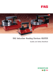
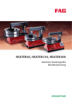
FAG PowerTherm
HEATER35
HEATER150
HEATER300
HEATER600
HEATER1200
User manual
FAG PowerTherm
Page
Features
Safety guidelines....................................................................... 3
HEATER35 to HEATER1200 ......................................................... 3
Scope of delivery ....................................................................... 4
Initial operation of devices
Safety guidelines....................................................................... 5
Trolley for HEATER300................................................................ 6
Positioning of workpieces.......................................................... 6
Configuring HEATER35, 150, 300 ............................................... 7
Configuring HEATER600, 1200 ................................................... 8
Heating of rolling bearings
Temperature-controlled heating process.................................... 10
Time-controlled heating process................................................ 11
Troubleshooting
Error messages in the display .................................................... 11
Alignment of ledges................................................................... 12
Technical data
HEATER35.................................................................................. 13
HEATER150................................................................................ 14
HEATER300................................................................................ 15
HEATER600................................................................................ 16
HEATER1200.............................................................................. 17
Spare parts
Accessories
Ordering designations
HEATER35.................................................................................. 18
HEATER150................................................................................ 19
HEATER300................................................................................ 20
HEATER600................................................................................ 21
HEATER1200.............................................................................. 22
Specifications............................................................................ 23
2
BA 18
Schaeffler Group Industrial
FAG PowerTherm
Features
This manual is valid for the HEATER35, 150, 300, 600, 1200.
The HEATERs are supplied in appropriate packaging. The packaging
and the device should be checked immediately for any damage
during transit. Photograph any damage and inform the carrier
without delay.
Safety guidelines
Caution!
It is essential that all instructions in this user manual are observed.
Operating personnel must be authorised. Unauthorised persons
should be kept at a distance during heating; it may be appropriate
to close off the area.
Safety regulations must be kept ready with the device and observed.
Heating devices must be operated and stored in dry rooms only –
otherwise there is a risk of corrosion.
Remove any contamination and oil residues immediately.
Ledges must be handled carefully; mechanical damage,
deformation and moisture must be avoided.
Repairs should only be carried out by FAG Industrial Services (F’IS)
or authorised companies.
Only HEATER genuine spare parts should be used.
Schaeffler KG assumes no liability for damage arising from incorrect
handling, negligence, modifications to the heating device or a
failure to provide information to third parties.
HEATER35 to HEATER1200
The devices are used to heat rolling bearings, including sealed or
greased bearings, for the purposes of easier mounting. They can
also be used to heat other rotationally symmetrical steel parts such
as bushes, rings, gears, etc. The permissible heating temperatures
for INA and FAG brand bearings are given in the corresponding
catalogues. For other products, the data provided by the
manufacturer should be taken as valid.
Function
The heart of each of the five heating devices is a live electric coil with
an iron core (primary circuit). This induces a high current at low
voltage in a short-circuited secondary circuit (a bearing or round
workpiece). The part to be mounted is heated quickly; the device
itself, the ledges and non-metallic components remain cool.
After heating, the parts are demagnetised and voltage-free.
Safe operation of the device is ensured by means of an integrated
temperature cut-off switch, a current regulator (thyristor) and an
overcurrent protector. The devices can be operated continuously
without the need for cooling.
Schaeffler Group Industrial
BA 18
3
FAG PowerTherm
Scope of delivery
HEATER35
Heating device, slewing ledge for bore diameters from 70 mm,
magnetic temperature sensor, metal box, safety gloves.
HEATER150
Heating device, slewing ledge for bore diameters from 100 mm,
magnetic temperature sensor, safety gloves.
HEATER300
Heating device, slewing ledge for bore diameters from 115 mm,
magnetic temperature sensor, safety gloves.
Accessories: Trolley HEATER300.TROLLEY, Figure 1.
HEATER600
HEATER1200
Caution!
4
BA 18
141 172
Figure 1
HEATER300.TROLLEY
Heating device, vertical ledge for bore diameters from 145 mm,
magnetic temperature sensor, four support blocks, safety gloves.
Heating device, vertical ledge for bore diameters from 215 mm,
magnetic temperature sensor, four support blocks, safety gloves.
The devices are top heavy – there is a risk of tilting.
When transporting with a fork lift truck or crane always pay
attention to the fact that, due to the copper coil, the centre of gravity
is located near the top, not in the middle. Aids must be designed in
accordance with the weight of the heating devices.
Schaeffler Group Industrial
Initial operation of devices
Safety guidelines
Danger!
Caution!
HEATER should never be used in rooms with an explosion risk.
Persons with pacemakers must not use the devices or stay in their
vicinity. Sensitive devices such as wristwatches, information media
with a magnetic strip, electronic devices etc. may be rendered
unusable – a safe distance of 2 metres must be maintained.
The material must be suitable for induction heating. The workpiece
must be of a closed shape.
Workpiece weight limits must be observed:
■ HEATER35: max. 35 kg
■ HEATER150: max. 150 kg
■ HEATER300: max. 300 kg
■ HEATER600: max. 600 kg
■ HEATER1200: max. 1200 kg
Work steps:
■ Place the HEATER on a stable, flat surface.
■ Ensure that the voltage of the power supply matches the voltage
indicated on the identification plate.
■ Connect to the mains supply.
If necessary, the mains plug should be changed
by skilled personnel
■ HEATER35: 3 strand cable; BROWN = live, BLUE = neutral,
YELLOW-GREEN = earth (230 V, see rating plate).
■ HEATER150, 300, 600: Mains plug with two phases
(400 V, see rating plate)
■ HEATER1200: Connect directly in terminal box, Figure 2
(400 V, see rating plate).
Live L1 (R)
No connection
Live L2 (S)
Main switch
No connection
Main switch
Schaeffler Group Industrial
141 173
Figure 2
Terminal box on HEATER1200
BA 18
5
FAG PowerTherm
Trolley for HEATER300
Mount the trolley handle and wheels using the screws supplied,
Figure 3. Fasten the heating device to the support surface using four
M8⫻30 screws, Figure 4.
Figure 3
Assembling the trolley for
HEATER300
141 174
2 M10⫻12 screws for handle
8 M10⫻M12 screws for castors
8 M10⫻M12 screws for fixed wheels
Figure 4
Fastening HEATER300 to
the trolley with screws
141 175
4 M8⫻30 screws
Positioning of workpieces
Caution!
Clean the ledges and magnetic temperature sensor.
Ensure that the inside diameter of the bearing is filled optimally,
Figure 5, . The larger the cross-section of the ledge that is used,
the shorter the heating time. On rolling bearings, position
the magnetic temperature sensor as centrally as possible on
the end face of the inner ring, Figure 5, .
Figure 5
Optimally used ledge cross-section
and correct position of
the temperature sensor
6
BA 18
141 158
Optimally used ledge cross-section
Position of the temperature sensor
Schaeffler Group Industrial
Configuring
HEATER35, 150, 300
Caution!
Grease the ground surfaces of the ledges.
Position the horizontal ledge correctly.
Work steps: see Figure 6:
■ Swivel the horizontal slewing ledge to the side.
■ Place the bearing on the circular area above the induction coil or on the slewing ledge .
■ Move the slewing ledge back to its original position, ground side
downwards. Two identical bearings can be heated
simultaneously on the slewing ledge or one of the accessory
ledges.
■ The weight limits must be observed.
Accessory ledges
Suitable accessory ledges should be used for smaller bore
diameters. Remove the slewing ledge from the shaft and position
the accessory slewing ledge on the stud. Simply place the accessory
slewing ledges available for the HEATER35 and the HEATER150 with
the ground side downwards on the ground end faces of the two
vertical ledges.
Induction coil
Slewing ledge
Schaeffler Group Industrial
141 176
Figure 6
HEATER35
Configuration identical to
HEATER150, 300
BA 18
7
FAG PowerTherm
Accessory extension pieces
For the heating of bearings with a larger cross-section, place two
accessory extension pieces on the vertical posts, Figure 7.
Figure 7
HEATER35, 150, 300
Extension pieces for larger bearing
cross-sections
141 161
Extension pieces
Configuring HEATER600, 1200
Caution!
Grease the ground surfaces of the ledges.
The vertical ledge must lie flat.
Work steps: see Figure 8:
■ Lift the vertical ledge manually or using hoisting equipment.
■ Place the bearing horizontally on the support blocks in
the support rails and centre.
■ Lower the vertical ledge again until it lies flat. Do not tilt or rotate.
Use support blocks during horizontal positioning.
Provide additional support for large rolling bearings projecting
beyond the support rails. The operator console can be rotated
90 degrees to a convenient position.
Figure 8
HEATER600, 1200
8
BA 18
141 177
4 support rails
Support blocks
Movable vertical ledge
Swivelling operator console
Schaeffler Group Industrial
Lifting fixture for HEATER1200
If the heating devices HEATER600 or HEATER1200 are equipped with
a lifting fixture, the vertical ledge can be raised and lowered easily
via remote control. See the separate user manual.
Accessory ledges
Schaeffler Group Industrial
141 178
Figure 9
HEATER1200 with lifting fixture
For optimum heating of workpieces with smaller inside diameters,
use the corresponding accessory vertical ledges.
BA 18
9
FAG PowerTherm
Heating of rolling bearings
Danger!
Caution!
Safety gloves must be worn.
Before starting the heating process, ensure that the horizontal ledge
is correctly positioned.
Connect the temperature sensor and position it correctly.
Do not heat rolling bearings to more than +120 °C.
Temperature-controlled
heating process
Work steps: see Figure 10:
■ Switch on the power supply (main switch: see Figure 24,
page 22). The display will show +110 °C.
■ Set the temperature to a value between +40 °C and +240 °C
(rolling bearings, max. +120 °C). Start the heating process using
the Start/Stop button .
■ When the selected temperature is reached, an acoustic signal
sounds and the selected temperature value flashes in the
display :
– Acknowledge using the Start/Stop button , detach the
magnetic temperature sensor and remove the workpiece using
safety gloves.
Self-compensating function
The function operates as follows:
■ If the heated part is not removed and its temperature decreases
by 5 °C, the process is repeated up to five times.
■ When the selected temperature value flashes in the display,
the process described above should be terminated.
Interruption of heating
The heating process can be interrupted at any time using
the Start/Stop button .
Figure 10
Display and control panel
10
BA 18
141 179
Display
Buttons for setting the temperature
Start/Stop button
Temperature display
Time display
Schaeffler Group Industrial
Time-controlled
heating process
Caution!
Interruption of heating
Troubleshooting
Error messages in the display
Danger!
Display, errors, actions
Schaeffler Group Industrial
Work steps: see Figure 10:
Do not connect the temperature sensor.
■ Switch on the power supply (main switch: see page 18 to
page 21). The display will show +110 °C.
■ Press the button Time display , the display will now
show 00.00.
■ Use the temperature setting buttons to set the desired heating
time up to max. 99 min + 59 s (99.59).
■ Start the heating process using the Start/Stop button .
■ The time shown in the display counts down to 00.00 and
then triggers an acoustic signal.
■ Acknowledge using the Start/Stop button and remove
the workpiece using safety gloves.
The heating process can be interrupted at any time using
the Start/Stop button .
The display may show the error messages E01, E02, E10 and E12;
see table Display, errors, actions.
Before opening the device, disconnect the power supply.
Display
code
Error
Actions and remedies
E01
Magnetic temperature sensor
inoperative
Check:
■ Is the temperature sensor
connected?
■ Is the power cable in working
order?
E02
The temperature is increasing
by less than +1 °C within:
1 minute: HEATER35
3 minutes: HEATER150
5 minutes: HEATER300, 600
10 minutes: HEATER1200
Check:
■ Is the temperature sensor
correctly positioned?
■ Are the temperature sensor
and power cable intact?
■ Is the bearing/workpiece too
heavy?
■ Is the shape and material
suitable for induction heating?
E10
Electronic system is not
measuring any zero crossing
Check:
■ Are the cable connections of
the circuit board correct?
(replace main circuit board if
necessary)
E12
Main power circuit interrupted
Check:
■ Are all the electronic plug-in
connections made correctly?
■ Is the cable connection of the
thyristor to the high voltage
circuit board in working order?
(if necessary, replace the
circuit board and test the
device)
BA 18
11
FAG PowerTherm
Alignment of ledges
The slewing ledge (support ledge) in HEATER35 and HEATER150
consists of a large number of transformer sheets permanently
bonded together.
HEATER300, 600, 1200: The slewing ledge and the vertical ledges
can be adjusted, for example if the device is generating a large
amount of noise.
Work steps:
■ Switch off the HEATER using the Start/Stop button.
– Ensure that the ground ledge surfaces are smooth and
greased.
– Check that the horizontal slewing ledge is laid flat on
the vertical ledges.
– With HEATER600, 1200 the vertical ledge must fit correctly.
■ Switch on the device.
Screws
Slewing ledge
141 180
Figure 11
HEATER300
Alignment of slewing ledge
Screws
Vertical ledge
141 181
Figure 12
HEATER600, 1200
Alignment of vertical ledge
HEATER is still too noisy.
Work steps: see Figure 11 and Figure 12:
■ Switch off the device using the Start/Stop button.
– Loosen the screws in the slewing ledge / vertical
ledge by 1/4 turn anticlockwise.
– Switch on the device and the ledge should align itself;
if not, use a plastic hammer to assist the process.
– Retighten the screws .
■ Switch off the device.
12
BA 18
Schaeffler Group Industrial
Technical data
HEATER35
Dimensions (W⫻H⫻L)
Designation
Technical data
Power consumption
max. 3,6 kVA at 230 V
max. 2,2 kVA at 110 V
Voltage and frequency
115 V to 240 V (50 Hz/60 Hz)
Current
16 A
Temperature display
+50 °C to +240 °C
Mass
31 kg
Workpiece mass
max. 35 kg
Designation
Dimensions in mm
Heating device
260⫻360⫻420
Slewing ledge
50⫻ 50⫻280
141 182
Figure 13
HEATER35
Circuit diagram
Main switch
Coil
Circuit board for high voltage
Magnetic temperature sensor
Circuit board for low voltage
Schaeffler Group Industrial
141 183
Figure 14
Circuit diagram for HEATER35
BA 18
13
FAG PowerTherm
Dimensions (W⫻H⫻L)
Figure 15
HEATER150
14
BA 18
Designation
Technical data
Power consumption
max. 12,8 kVA
Voltage and frequency
200 V to 600 V (50 Hz/60 Hz)
Current
32 A
Temperature display
+50 °C to +240 °C
Mass
51 kg
Workpiece mass
max. 150 kg
Designation
Dimensions in mm
Heating device
260⫻505⫻440
Slewing ledge
70⫻ 70⫻350
141 184
HEATER150
Schaeffler Group Industrial
HEATER300
Dimensions (W⫻H⫻L)
Designation
Technical data
Power consumption
max. 12,8 kVA
Voltage and frequency
200 V to 600 V (50 Hz/60 Hz)
Current
32 A
Temperature display
+50 °C to +240 °C
Mass
75 kg
Workpiece mass
max. 300 kg
Designation
Dimensions in mm
Heating device
310⫻880⫻565
Slewing ledge
80⫻ 80⫻490
Schaeffler Group Industrial
141 185
Figure 16
HEATER300
BA 18
15
FAG PowerTherm
Dimensions (W⫻H⫻L)
Figure 17
HEATER600
16
BA 18
Designation
Technical data
Power consumption
max. 25 kVA
Voltage and frequency
200 V to 600 V (50 Hz/60 Hz)
Current
63 A
Temperature display
+50 °C to +240 °C
Mass
350 kg
Workpiece mass
max. 600 kg
Designation
Dimensions in mm
Heating device
820⫻1100⫻1070
Vertical ledge
100⫻ 100⫻ 700
141 186
HEATER600
Schaeffler Group Industrial
HEATER1200
Dimensions (W⫻H⫻L)
Designation
Technical data
Power consumption
max. 40 kVA
Voltage and frequency
200 V to 600 V (50 Hz/60 Hz)
Current
100 A
Temperature display
+50 °C to +240 °C
Mass
850 kg
Workpiece mass
max. 1200 kg
Designation
Dimensions in mm
Heating device
1050⫻1500⫻1270
Vertical ledge
150⫻ 150⫻ 850
Circuit diagram
141 187
Figure 18
HEATER1200
The circuit diagram for HEATER150, HEATER300, HEATER600 and
HEATER1200 is identical.
Main switch
Capacitor
Coil
Circuit board for high voltage
Magnetic temperature sensor
Circuit board for low voltage
Schaeffler Group Industrial
141 188
Figure 19
Circuit diagram
HEATER150, 300, 600, 1200
BA 18
17
FAG PowerTherm
Spare parts
Accessories
Ordering designations
HEATER35
Power supply connector
Coil
U-shaped core
Housing cover
Slewing ledge
Operator terminal
Operator circuit board
Main switch
Jack for temperature sensor
Baseplate
Main circuit board
Spare parts
Ordering designations
141 189
Figure 20
HEATER35
Designation
Ordering designation
Temperature sensor
HEATER.SENSOR
Controller
HEATER35.ETRONIC
Main switch
HEATER35.MAIN.SWITCH
Main circuit board
HEATER35.BOARD1
Operator circuit board
HEATER35.BOARD2
Thyristor
HEATER35.THYRISTOR
Display
HEATER35.DISPLAY
Slewing ledge
HEATER35.LEDGE-701)
1)
Accessories
Ordering designations
Smallest workpiece bore diameter.
Designation
Ordering designation
Support ledges, dimensions in mm
10⫻10⫻280
HEATER35.LEDGE-151)
14⫻14⫻280
HEATER35.LEDGE-201)
Slewing ledges, dimensions in mm
25⫻25⫻280
HEATER35.LEDGE-351)
30⫻30⫻280
HEATER35.LEDGE-451)
40⫻40⫻280
HEATER35.LEDGE-601)
Two extension pieces, dimensions in mm
50⫻50⫻120
Clamping temperature sensor
1)
18
BA 18
HEATER35.ADAPTER1201)
HEATER.SENSOR-CLAMP
Smallest workpiece bore diameter.
Schaeffler Group Industrial
HEATER150
Baseplate
Power supply connector
Main switch
Coil
U-shaped core
Housing cover
Slewing ledge
Operator terminal
Operator circuit board
Jack for temperature sensor
Capacitor
Main circuit board
Spare parts
Ordering designations
141 190
Figure 21
HEATER150
Designation
Ordering designation
Temperature sensor
HEATER.SENSOR
Controller
HEATER150.ETRONIC
Main switch
HEATER150.MAIN.SWITCH
Main circuit board
HEATER150.BOARD1
Operator circuit board
HEATER150.BOARD2
Thyristor
HEATER150.THYRISTOR
Display
HEATER150.DISPLAY
Slewing ledge
HEATER150.LEDGE-1001)
1)
Accessories
Ordering designations
Smallest workpiece bore diameter.
Designation
Ordering designation
Support ledges, dimensions in mm
14⫻14⫻350
HEATER150.LEDGE-201)
Slewing ledges, dimensions in mm
20⫻20⫻350
HEATER150.LEDGE-301)
30⫻30⫻350
HEATER150.LEDGE-451)
40⫻40⫻350
HEATER150.LEDGE-601)
50⫻50⫻350
HEATER150.LEDGE-701)
60⫻60⫻350
HEATER150.LEDGE-851)
Two extension pieces, dimensions in mm
70⫻70⫻150
HEATER150.ADAPTER1501)
70⫻70⫻200
HEATER150.ADAPTER2001)
Clamping temperature sensor
1)
Schaeffler Group Industrial
HEATER.SENSOR-CLAMP
Smallest workpiece bore diameter.
BA 18
19
FAG PowerTherm
HEATER300
Baseplate
U-shaped core
Housing cover
Support rails
Rotation point
Slewing ledge
Operator terminal
Jack for temperature sensor
Control cabinet
Main switch
Operator circuit board
Capacitor
Thyristor
Main circuit board
Coils
Spare parts
Ordering designations
141 191
Figure 22
HEATER300
Designation
Ordering designation
Temperature sensor
HEATER.SENSOR
Controller
HEATER300.ETRONIC
Main switch
HEATER300.MAIN.SWITCH
Main circuit board
HEATER300.BOARD1
Operator circuit board
HEATER300.BOARD2
Thyristor
HEATER300.THYRISTOR
Display
HEATER300.DISPLAY
Slewing ledge
HEATER300.LEDGE-1151)
Two support rails
HEATER300.BLADE
1)
Accessories
Ordering designations
Smallest workpiece bore diameter.
Designation
Ordering designation
Slewing ledges, dimensions in mm
20⫻20⫻490
HEATER300.LEDGE-301)
30⫻30⫻490
HEATER300.LEDGE-451)
40⫻40⫻490
HEATER300.LEDGE-601)
50⫻50⫻490
HEATER300.LEDGE-701)
60⫻60⫻490
HEATER300.LEDGE-851)
70⫻70⫻490
HEATER300.LEDGE-1001)
Two extension pieces, dimensions in mm
BA 18
HEATER300.ADAPTER1501)
80⫻80⫻200
HEATER300.ADAPTER2001)
Trolley
HEATER300.TROLLEY
Clamping temperature sensor
HEATER.SENSOR-CLAMP
1)
20
80⫻80⫻150
Smallest workpiece bore diameter.
Schaeffler Group Industrial
HEATER600
Support rails
Support blocks
Vertical ledge
Main circuit board
Thyristor
Capacitor
Jack for temperature sensor
Operator terminal
Swivelling operator console
Operator circuit board
Main switch
Coils
U-shaped core
Power supply connector
Spare parts
Ordering designations
141 192
Figure 23
HEATER600
Designation
Ordering designation
Temperature sensor
HEATER.SENSOR
Controller
HEATER600.ETRONIC
Main switch
HEATER600.MAIN.SWITCH
Main circuit board
HEATER600.BOARD1
Operator circuit board
HEATER600.BOARD2
Thyristor
HEATER600.THYRISTOR
Display
HEATER600.DISPLAY
Vertical ledge
HEATER600.LEDGE-1451)
Four support rails
HEATER600.SUPPORT.BLADE
Four support blocks
HEATER600.BASE.PLATE
1)
Accessories
Ordering designations
Smallest workpiece bore diameter.
Designation
Ordering designation
Vertical ledges, dimensions in mm
30⫻40⫻700
HEATER600.LEDGE-451)
40⫻40⫻700
HEATER600.LEDGE-601)
50⫻50⫻700
HEATER600.LEDGE-701)
60⫻60⫻700
HEATER600.LEDGE-851)
70⫻70⫻700
HEATER600.LEDGE-1001)
80⫻80⫻700
HEATER600.LEDGE-1151)
90⫻90⫻700
HEATER600.LEDGE-1301)
Clamping temperature sensor
1)
Schaeffler Group Industrial
HEATER.SENSOR-CLAMP
Smallest workpiece bore diameter.
BA 18
21
FAG PowerTherm
HEATER1200
Support rails
Support blocks
Vertical ledge
Main circuit board
Thyristor
Capacitor
Jack for temperature sensor
Operator terminal
Swivelling operator console
Operator circuit board
Main switch
Coils
U-shaped core
Power supply connector
Spare parts
Ordering designations
141 193
Figure 24
HEATER1200
Designation
Ordering designation
Temperature sensor
HEATER.SENSOR
Controller
HEATER1200.ETRONIC
Main switch
HEATER1200.MAIN.SWITCH
Main circuit board
HEATER1200.BOARD1
Operator circuit board
HEATER1200.BOARD2
Thyristor
HEATER1200.THYRISTOR
Display
HEATER1200.DISPLAY
Vertical ledge
HEATER1200.LEDGE-2151)
Four support rails
HEATER1200.BLADE
Four support blocks
HEATER1200.BASE.PLATE
1)
Accessories
Ordering designations
Smallest workpiece bore diameter.
Designation
Ordering designation
Vertical ledges, dimensions in mm
60⫻ 60⫻850
HEATER1200.LEDGE-851)
80⫻ 80⫻850
HEATER1200.LEDGE-1151)
100⫻100⫻850
HEATER1200.LEDGE-1451)
Clamping temperature sensor
1)
22
BA 18
HEATER.SENSOR-CLAMP
Smallest workpiece bore diameter.
Schaeffler Group Industrial
Specifications
EU Declaration of Conformity
Electrical safety:
■ IEC 335-1 Class 1,
■ IEC 664-1 Class 1 and
■ Safety Class 1.
The heating devices comply with:
■ Low Voltage Directive 73/23/EEC and
■ EMC Directive 89/336/EEC.
EMC emission:
■ EN 55011,
■ EN 60555-2 and
■ EN 60555-3.
EMC immunity:
■ IEC 801-2,
■ IEC 801-3,
■ IEC 801-4 and
■ IEC 801-5.
Schaeffler Group Industrial
BA 18
23
MATNR 032837534-0000 / BA 18 / GB-D / 2007052 / Printed in Germany by Frankendruck
Schaeffler KG
Every care has been taken to ensure the
Georg-Schäfer-Strasse 30
correctness of the information contained
97421 Schweinfurt (Germany)
in this publication but no liability can be
Internet www.fag.com
accepted for any errors or omissions.
E-Mail [email protected]
In Germany:
Phone 0180 5003872
Fax
0180 5003873
From Other Countries:
We reserve the right to make technical
changes.
© Schaeffler KG · 2007, May
This publication or parts thereof may not
Phone +49 9721 91-0
be reproduced without our permission.
Fax
BA 18 GB-D
+49 9721 91-3435