Transcript
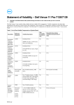
C O N N E C T I O N S
TQ LIMIT
ACCEL
DECEL
IR COMP
MIN SPD
MAX SPD
1
S T E P
2
STEP #1
R501
230 - 115
ARMATURE VOLTAGE
SWITCH (SW501)
90 or 180 VDC
S T E P
# 3
WIRE THE CONTROL
AS SHOWN THROUGH
THE CONDUIT HOLES
IN THE BOTTOM PLATE.
POWER
REMOVE THE SIX (6)
PHILLIPS SCREWS ON
THE FRONT CASE.
SW501
MOV501
# 4
ASSURE THAT THE
VOLTAGE SWITCH
SETTINGS ARE CORRECT
(SW501 & SW502)
C503
G U I D E
R502
S T A R T
MOV502
Q U I C K
SO502
T501
AC LINE VOLTAGE
SWITCH (SW502)
115 or 230 VAC
S3 S2 S1
NEMA4X SCR MOTOR CONTROLS
90 - 180 SW502
GS10 & GS10-R
F502
ON
L2 FRM SW L1
A2 TO SW A1
L2 TO SW L1
A2 FRM SW A1
OFF
ADJUSTABLE SPEED
DC MOTOR CONTROL
# 5
REPLACE SIX SCREWS
ON FRONT CASE &
FIVE SCREWS ON
BOTTOM PLATE.
A1
A2
L1
L2-230
0
4
SPEED
S T E P
TB501
F2
The field output is for shunt
wound motors only. Do not
make any connections to
F1 and F2 when using a
permanent magnet (PM) motor.
For field motor connections,
see "Field Voltage" in
Specifications box below.
F1
2 3
1
7 8 9
3
F501
MOV503
L2-115
FIELD OUTPUT
CONNECTIONS
4 5 6
NOTE: THE TWO SHORTER
SCREWS (#6 - 32 x 2 ½) ON
THE FRONT CASE ARE USED
AT HOLE LOCATIONS 5 & 6.
+
230 VAC
115 VAC
EARTH
GROUND
(GREEN
SCREW)
6
5
O P E R A T I O N
CUSTOMER SUPPLIED
WATERTIGHT CORD
CONNECTORS (2)
G S 10 Non-Reversing Speed Control
1.
2.
3.
4.
1
S T E P
# 2
REMOVE THE FIVE (5)
PHILLIPS SCREWS ON
THE BOTTOM PLATE.
FIELD
OUTPUT
2
BOTTOM PLATE
3
CUSTOMER SUPPLIED
WATERTIGHT CORD
CONNECTORS (2)
4
5
DO NOT REMOVE
THE THREE (3) SCREWS SECURING
THE BOTTOM PLATE TO THE HEATSINK
© 2009 Applied Industrial Technologies, Inc. All Rights Reserved. C-0209-11-5139
Set the speed adjust dial to “0” (full CCW).
Apply AC line voltage.
Set the POWER switch to the ON position.
Slowly advance the speed adjust potentiometer CW.
The motor slowly accelerates as the potentiometer is
turned CW. Continue until the desired speed is reached.
5. To coast the motor to a stop, turn the speed adjust
potentiometer to “0” or set the POWER switch to the
OFF position.
G S 10-R Reversing Speed Control
1. Set the FORWARD/OFF/REVERSE switch to the OFF
position.
2. Set the speed adjust potentiometer to “0” (full CCW).
3. Apply AC line voltage.
4. Set the FOWARD/OFF/REVERSE switch to the desired
direction of rotation.
5. Slowly advance the speed adjust potentiometer CW.
The motor slowly accelerates as the potentiometer is
turned CW. Continue until the desired speed is reached.
6. To coast the motor to a stop, turn the speed adjust
potentiometer to “0” or set the
FORWARD/OFF/REVERSE switch to the OFF position.
LINE
VOLTAGE
INPUT
(115 or 230 VAC)
MOTOR
ARMATURE
S P E C I F I C A T I O N S
AC Line Voltage . . .115 VAC or 230 VAC, ±10%, 50/60 Hz, single phase
Horsepower Range with 115 VAC applied . . . . . . . . . . . . . . . . .1/8 - 1 HP
Horsepower Range with 230 VAC applied . . . . . . . . . . . . . . . . .1/4 - 2 HP
Maximum Armature Current . . . . . . . . . . . . . . . . . . . . . . . . . . . . . .10 ADC
Maximum Field Current . . . . . . . . . . . . . . . . . . . . . . . . . . . . . . . . . .1 ADC
Field Voltage
for 115 VAC Input . . . . . . .50 VDC (F1 to L1); 100 VDC (F1 to F2)
for 230 VAC Input . . . . . .100 VDC (F1 to L1); 200 VDC (F1 to F2)
Form Factor . . . . . . . . . . . . . . . . . . . . . . . . . . . . . . . . .1.37 at base speed
Analog Input Voltage Range (signal must be isolated; S1 to S2):
for 0 - 90 VDC Armature Voltage . . . . . . . . . . . . . . . . .0 - 1.4 VDC
for 0 - 180 VDC Armature Voltage . . . . . . . . . . . . . . . .0 - 2.8 VDC
Input Impedance (S1 to S2) . . . . . . . . . . . . . . . . . . . . . . . . . . . . .3M ohms
Load Regulation . . . . . . . . . . . . . . . . . . . . . . . . .1% base speed or better
Style . . . . . . . . . . . . . . . . . . . . . . . . . . . . . . . . . . . . . . . . . . . . . . .NEMA 4X
7. To reverse direction:
a. Set the FORWARD/OFF/REVERSE switch to the OFF
position.
b. After the motor comes to a complete stop, set the
FORWARD/OFF/REVERSE switch to the desired direction of
rotation.
For a complete user manual visit www.Applied.com/gsmum