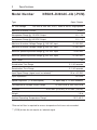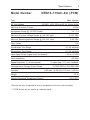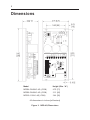
1
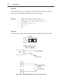
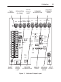
N R G - 4 Q
S e r i e s
USER MANUAL
MODELS
NRG02-D240AC-4Q
NRG02-D240AC-4Q-PCM
NRG05-D240AC-4Q
NRG05-D240AC-4Q-PCM
NRG10-115AC-4Q
NRG10-115AC-4Q-PCM
Four Quadrant, Regenerative PWM Drives
For DC Brush Motors
Copyright © 2005 by
Minarik Corporation
All rights reserved. No part of this manual may be reproduced or transmitted in any
form without written permission from Minarik Corporation. The information and
technical data in this manual are subject to change without notice. Minarik
Corporation and its Divisions make no warranty of any kind with respect to this
material, including, but not limited to, the implied warranties of its merchantability
and fitness for a given purpose. Minarik Corporation and its Divisions assume no
responsibility for any errors that may appear in this manual and make no
commitment to update or to keep current the information in this manual.
Printed in the United States of America.
i
Safety Warnings
• This symbol
l denotes an important safety message.
Please read these
sections very carefully before performing any calibration, repair, or other
procedure contained in this manual.
• Have a qualified electrical maintenance technician install, adjust, and service
this equipment. Follow the National Electrical Code and all other applicable
electrical and safety codes, including the provisions of the Occupational Safety
and Health Act (OSHA), when installing equipment.
• Reduce the chance of an electrical fire, shock, or explosion by proper grounding,
over current protection, thermal protection, and enclosure. Follow sound
maintenance procedures.
L
It is possible for a drive to run at full speed as a result of a
component failure. Minarik strongly recommends the installation
of a master switch in the main power input to stop the drive in an
emergency.
Circuit potentials are at 120 VAC or 240 VAC above earth ground.
Avoid direct contact with the printed circuit board or with circuit
elements to prevent the risk of serious injury or fatality. Use a
non-metallic screwdriver for adjusting the calibration trimpots.
Use insulated tools if working on this drive with power applied.
ii
Contents
Specifications . . . . . . . . . . . . . . . . . . . . . . . . . . . . . . . . . . . . . . . . . . . . . . . .1
Dimensions . . . . . . . . . . . . . . . . . . . . . . . . . . . . . . . . . . . . . . . . . . . . . . . . . .4
Installation
. . . . . . . . . . . . . . . . . . . . . . . . . . . . . . . . . . . . . . . . . . . . . . . . . .5
Mounting
. . . . . . . . . . . . . . . . . . . . . . . . . . . . . . . . . . . . . . . . . . . . . . .5
Wiring . . . . . . . . . . . . . . . . . . . . . . . . . . . . . . . . . . . . . . . . . . . . . . . . . .6
Shielding guidelines . . . . . . . . . . . . . . . . . . . . . . . . . . . . . . . . . . .7
Speed adjust potentiometer . . . . . . . . . . . . . . . . . . . . . . . . . . . . . . . . . .8
Heat sinking . . . . . . . . . . . . . . . . . . . . . . . . . . . . . . . . . . . . . . . . . . . . .9
Line fusing
. . . . . . . . . . . . . . . . . . . . . . . . . . . . . . . . . . . . . . . . . . . . . .9
Cage-clamp terminals
. . . . . . . . . . . . . . . . . . . . . . . . . . . . . . . . . . . . .10
Connections . . . . . . . . . . . . . . . . . . . . . . . . . . . . . . . . . . . . . . . . . . . . .11
Power input connections
Motor connections
. . . . . . . . . . . . . . . . . . . . . . . . . . . . . .11
. . . . . . . . . . . . . . . . . . . . . . . . . . . . . . . . . . .12
Regenerative dump resistor connections . . . . . . . . . . . . . . . . . . .12
Top board terminals . . . . . . . . . . . . . . . . . . . . . . . . . . . . . . . . . .14
Signal and optional switch connections
Speed adjust potentiometer connections
. . . . . . . . . . . . . . . . . . . . . . . .16
. . . . . . . . . . . . . . . . . . . . . . .18
Voltage follower . . . . . . . . . . . . . . . . . . . . . . . . . . . . . . . . . . . . .19
Slide switches
. . . . . . . . . . . . . . . . . . . . . . . . . . . . . . . . . . . . . . . . . .20
ARMATURE VOLTAGE OUT (SW501) . . . . . . . . . . . . . . . . . . . . .20
FEEDBACK SELECT (SW502)
Headers
. . . . . . . . . . . . . . . . . . . . . . . . . .20
. . . . . . . . . . . . . . . . . . . . . . . . . . . . . . . . . . . . . . . . . . . . . . .20
INHIBIT PERSONALITY (JMP501)
. . . . . . . . . . . . . . . . . . . . . . .20
CONTROL MODE (JMP502) . . . . . . . . . . . . . . . . . . . . . . . . . . . .21
INHIBIT MODE (JMP503) . . . . . . . . . . . . . . . . . . . . . . . . . . . . . .21
CURRENT LIMIT OUT (J502) . . . . . . . . . . . . . . . . . . . . . . . . . . .21
OUTPUT HEADER (J504) . . . . . . . . . . . . . . . . . . . . . . . . . . . . . .22
Operation
. . . . . . . . . . . . . . . . . . . . . . . . . . . . . . . . . . . . . . . . . . . . . . . . . 23
Before applying power
Startup and shutdown
. . . . . . . . . . . . . . . . . . . . . . . . . . . . . . . . . . . .23
. . . . . . . . . . . . . . . . . . . . . . . . . . . . . . . . . . . . .24
Contents
Reversing the drive: . . . . . . . . . . . . . . . . . . . . . . . . . . . . . . . . . .24
Starting and stopping methods . . . . . . . . . . . . . . . . . . . . . . . . . . . . . . .25
Line starting and line stopping
. . . . . . . . . . . . . . . . . . . . . . . . . .26
Automatic restart upon power restoration
Decelerating to minimum speed
. . . . . . . . . . . . . . . . . .26
. . . . . . . . . . . . . . . . . . . . . . . . .26
Inhibit terminals . . . . . . . . . . . . . . . . . . . . . . . . . . . . . . . . . . . . .27
Regenerative dump . . . . . . . . . . . . . . . . . . . . . . . . . . . . . . . . . . .28
Torque (Current) Control . . . . . . . . . . . . . . . . . . . . . . . . . . . . . . .31
NRG-4Q-PCM . . . . . . . . . . . . . . . . . . . . . . . . . . . . . . . . . . . . . . .31
Calibration
. . . . . . . . . . . . . . . . . . . . . . . . . . . . . . . . . . . . . . . . . . . . . . . . .32
Calibration procedure
. . . . . . . . . . . . . . . . . . . . . . . . . . . . . . . . . . . . .34
MINIMUM SPEED (MIN SPD) . . . . . . . . . . . . . . . . . . . . . . . . . . .35
INHIBIT OFFSET
. . . . . . . . . . . . . . . . . . . . . . . . . . . . . . . . . . .36
INPUT OFFSET . . . . . . . . . . . . . . . . . . . . . . . . . . . . . . . . . . . . .37
FORWARD MAXIMUM SPEED (FWD MAX) . . . . . . . . . . . . . . . . .38
REVERSE MAXIMUM SPEED (REV MAX)
REGULATION (IR COMP)
. . . . . . . . . . . . . . . . .38
. . . . . . . . . . . . . . . . . . . . . . . . . . . . .39
MOTOR TORQUE LIMIT and REGEN TORQUE LIMIT . . . . . . . . .40
FORWARD ACCELERATION (FWD ACCEL)
REVERSE ACCELERATION (REV ACCEL)
TACHOMETER (TACH)
. . . . . . . . . . . . . . . .42
. . . . . . . . . . . . . . . . .43
. . . . . . . . . . . . . . . . . . . . . . . . . . . . . . .44
Application Notes . . . . . . . . . . . . . . . . . . . . . . . . . . . . . . . . . . . . . . . . . . . .47
Connection to other Minarik devices . . . . . . . . . . . . . . . . . . . . . . . . . . .47
Optional speed adjust potentiometer connections . . . . . . . . . . . . . . . . .49
FWD-MIN SPD-REV Switch
. . . . . . . . . . . . . . . . . . . . . . . . . . . .49
Independent Adjustable Speeds
. . . . . . . . . . . . . . . . . . . . . . . . .50
Independent forward and reverse speeds
. . . . . . . . . . . . . . . . . .51
Independent forward and reverse speeds using a
FWD-MIN SPD-REV switch . . . . . . . . . . . . . . . . . . . . . . . . .52
Troubleshooting
. . . . . . . . . . . . . . . . . . . . . . . . . . . . . . . . . . . . . . . . . . . . .53
Before applying power:
. . . . . . . . . . . . . . . . . . . . . . . . . . . . . . . . . . . .53
iii
iv
Contents
Diagnostic LEDs . . . . . . . . . . . . . . . . . . . . . . . . . . . . . . . . . . . . . . . . .54
CURRENT LIMIT
. . . . . . . . . . . . . . . . . . . . . . . . . . . . . . . . . . . .54
MOTOR . . . . . . . . . . . . . . . . . . . . . . . . . . . . . . . . . . . . . . . . . . .54
REGEN
. . . . . . . . . . . . . . . . . . . . . . . . . . . . . . . . . . . . . . . . . . .54
OVER VOLTAGE COAST
. . . . . . . . . . . . . . . . . . . . . . . . . . . . . .55
CE Compliance . . . . . . . . . . . . . . . . . . . . . . . . . . . . . . . . . . . . . . . . . . . . . .60
Certificate of Compliance
. . . . . . . . . . . . . . . . . . . . . . . . . . . . . . . . . .60
Compliance Requirements . . . . . . . . . . . . . . . . . . . . . . . . . . . . . . . . . .61
OEM Responsibility
. . . . . . . . . . . . . . . . . . . . . . . . . . . . . . . . . .61
Installation . . . . . . . . . . . . . . . . . . . . . . . . . . . . . . . . . . . . . . . . .61
Enclosure
Wiring
. . . . . . . . . . . . . . . . . . . . . . . . . . . . . . . . . . . . . . . . .62
. . . . . . . . . . . . . . . . . . . . . . . . . . . . . . . . . . . . . . . . . . . .62
Grounding
. . . . . . . . . . . . . . . . . . . . . . . . . . . . . . . . . . . . . . . . .62
AC Line Filters . . . . . . . . . . . . . . . . . . . . . . . . . . . . . . . . . . . . . .63
Unconditional Warranty
. . . . . . . . . . . . . . . . . . . . . . . . . . . . . . . . . . . . . . .66
v
Illustrations
Figure 1.
Four Quadrant Operation
Figure 2.
NRG–4Q Dimensions . . . . . . . . . . . . . . . . . . . . . . . . . . . . . . . . . .4
. . . . . . . . . . . . . . . . . . . . . . . . . . . . . . .x
Figure 3.
Speed Adjust Potentiometer . . . . . . . . . . . . . . . . . . . . . . . . . . . . .8
Figure 4.
Cage-Clamp Terminal . . . . . . . . . . . . . . . . . . . . . . . . . . . . . . . . .10
Figure 5.
Bottom Board Connections . . . . . . . . . . . . . . . . . . . . . . . . . . . . .13
Figure 6.
Top Board Connections . . . . . . . . . . . . . . . . . . . . . . . . . . . . . . . .17
Figure 7.
Speed Adjust Potentiometer Connections
Figure 8.
Voltage Follower Connections . . . . . . . . . . . . . . . . . . . . . . . . . . .19
Figure 9.
Slide Switches, Headers and Terminals . . . . . . . . . . . . . . . . . . . .22
. . . . . . . . . . . . . . . . . .18
Figure 10.
Regenerative Dump Circuit Connection . . . . . . . . . . . . . . . . . . . .30
Figure 11.
Calibration Trimpot Layout
Figure 12.
Typical Motor Torque, Regen Torque and IR Comp Settings
. . . . . . . . . . . . . . . . . . . . . . . . . . . . .33
for NRG02/05-4Q Series Drives
. . . . . . . . . . . . . . . . . . . . . . . . .45
Figure 13. Typical Motor Torque, Regen Torque and IR Comp Settings
for NRG10-4Q Series Drives
. . . . . . . . . . . . . . . . . . . . . . . . . . .46
Figure 14.
NRG–4Q Connection to DIGI-LOK Controls . . . . . . . . . . . . . . . . .47
Figure 15.
NRG Connection to 200–0386A Limit Switch Logic Board . . . . . . .48
Figure 16.
FWD / MIN SPD / REV Switch . . . . . . . . . . . . . . . . . . . . . . . . . . .49
Figure 17.
Independent Adjustable Speeds (Forward Direction) . . . . . . . . . . .50
Figure 18.
Independent Forward and Reverse Speeds . . . . . . . . . . . . . . . . .51
Figure 19.
Independent Forward and Reverse Speeds Using a
Figure 20.
Diagnostic LED Location . . . . . . . . . . . . . . . . . . . . . . . . . . . . . . .56
Figure 21.
CE Shielding, Ground and Filtering Connections . . . . . . . . . . . . .64
FWD / MIN SPD / REV Switch . . . . . . . . . . . . . . . . . . . . . . . . . . .52
vi
Tables
Table 1.
Recommended Line Fuse Sizes
Table 2.
Inhibit Plug Harness Assembly
. . . . . . . . . . . . . . . . . . . . . . . . . .9
Table 3.
Regenerative Dump Resistor Values . . . . . . . . . . . . . . . . . . . . . .28
Table 4.
AC Line Filters . . . . . . . . . . . . . . . . . . . . . . . . . . . . . . . . . . . . . .63
. . . . . . . . . . . . . . . . . . . . . . . . . .27
vii
NRG–4Q Drives
Minarik’s NRG–4Q Series drives are four-quadrant, regenerative PWM
drives. These open chassis drives come with the following features:
Pulse width modulation. Lower form factor than SCR drives (1.03 versus
1.37) throughout the motor speed range. Motor runs with greater efficiency
and less maintenance.
Four quadrant regenerative operation. see Regenerative drives section on
page ix.
Inhibit personality. Set the inhibit for your application needs: regenerative
brake for fast stopping, or coast for slower stopping. Normally open or
normally closed.
On board fusing. Protects the drive from high line current.
Cage-clamp terminals. Quicker and easier wiring than screw terminals.
Regenerative braking. No contactors required. No electromechanical
components to overheat or wear out.
Reverse on the fly. Switch from forward to reverse instantaneously.
Dual voltage input. Power the drive with either 120 VAC or 240 VAC.
Autoranging power supply.
Tachogenerator feedback option. Improve the speed regulation from
approximately 1% (armature feedback) to 0.1% with tachogenerator
feedback.
viii
NRG-4Q Drives
Diagnostic LEDs. Allows easy visual inspection of the drive status. Motor,
regen, current limit, and over voltage.
+15 and –15 VDC supply (50 mA maximum capacity each). Power external
devices with the drive’s power supply.
User adjustable trimpots. Calibrate the drive precisely to your application
needs.
ix
Regenerative Drives
Most non-regenerative variable-speed DC drives control current flow to a
motor in one direction. The direction of current flow is the same direction as
the motor rotation. Non-regenerative drives operate in Quadrant 1, and also
in Quadrant 3 if the drive is reversible (see Figure 1 on page x).
Motors must stop before reversing direction. Unless dynamic braking is used,
non-regenerative drives cannot decelerate a load faster than coasting to a
lower speed.
Regenerative drives operate in two additional quadrants: Quadrant 2 and
Quadrant 4. In these quadrants, motor torque is in the opposite direction of
motor rotation. This allows regenerative drives to reverse a motor without
contactors or switches, to control an overhauling load, and to decelerate a
load faster than it would take to coast to a lower speed.
x
Regenerative Drives
Figure 1. Four Quadrant Operation
1
Specifications
Model Number
NRG02–D240AC–4Q (-PCM)
Type
AC Line Voltage
Open Chassis
120 VAC or 240 VAC, ±10%, 50Hz or 60 Hz, single phase
Maximum Continuous Armature Current
2 ADC
Horsepower Range @ 130 VDC Output
1/20 – 1/4
Horsepower Range @ 240 VDC Output
1/10 – 1/2
Maximum Armature Voltage Range @ 120 VAC Input
0–130 VDC
Maximum Armature Voltage Range @ 240 VAC Input
0–240 VDC
Minimum Speed Adjustment Range @ 120 VAC Input
0–60 VDC
Minimum Speed Adjustment Range @ 240 VAC Input
0–120 VDC
Form Factor
1.05
Acceleration Time Range
0.1–20 seconds
Deceleration Time Range
0.1–20 seconds
Input Signal Range (signal must be isolated)**
– 10 to +10 VDC
Input Impedance
Speed Regulation (% of base speed)
47k Ohm
1% open loop; 0.1% tach feedback
Tachogenerator Voltage Output Range
Vibration
7 V/1000 RPM to 50V/1000 RPM
0.5G max. (0–50 Hz); 0.1G max. (>50 Hz)
Weight
Ambient Operating Temperature Range*
1.9 lb
10°C–40°C
*External air flow is required to ensure temperature limits are not exceeded.
** (-PCM) drives do not require an isolated signal.
2
Specifications
Model Number
NRG05–D240AC–4Q (-PCM)
Type
AC Line Voltage
Open Chassis
120 VAC or 240 VAC, ±10%, 50Hz or 60 Hz, single phase
Maximum Armature Current
5 ADC
Horsepower Range @ 130 VDC Output
1/8 – 3/4
Horsepower Range @ 240 VDC Output
1/4 – 1.5
Maximum Armature Voltage Range @ 120 VAC Input
0–130 VDC
Maximum Armature Voltage Range @ 240 VAC Input
0–240 VDC
Minimum Speed Adjustment Range @ 120 VAC Input
0–60 VDC
Minimum Speed Adjustment Range @ 240 VAC Input
0–120 VDC
Form Factor
1.05
Acceleration Time Range
0.1–20 seconds
Deceleration Time Range
0.1–20 seconds
Input Signal Range (signal must be isolated)**
– 10 to +10 VDC
Input Impedance
47k Ohm
Speed Regulation (% of base speed)
1% open loop; 0.1% tach feedback
Tachogenerator Voltage Output Range
Vibration
7V/1000 RPM to 50V/1000 RPM
0.5G max. (0–50 Hz); 0.1G max. (>50 Hz)
Weight
Ambient Operating Temperature Range*
1.9 lb
10°C–40°C
*External air flow is required to ensure temperature limits are not exceeded.
** (-PCM) drives do not require an isolated signal.
Specifications
Model Number
NRG10–115AC–4Q (-PCM)
Type
AC Line Voltage
3
Open Chassis
120 VAC, ±10%, 50Hz or 60 Hz, single phase
Maximum Armature Current
10 ADC
Horsepower Range @ 130 VDC Output
1/4 – 1.5
Maximum Armature Voltage Range @ 120 VAC Input
0–130 VDC
Minimum Speed Adjustment Range @ 120 VAC Input
0–60 VDC
Form Factor
1.05
Acceleration Time Range
0.1–20 seconds
Deceleration Time Range
0.1–20 seconds
Input Signal Range (signal must be isolated)**
– 10 to +10 VDC
Input Impedance
Speed Regulation (% of base speed)
47k Ohm
1% open loop; 0.1% tach feedback
Tachogenerator Voltage Output Range
Vibration
7V/1000 RPM to 50V/1000 RPM
0.5G max. (0–50 Hz); 0.1G max. (>50 Hz)
Weight
Ambient Operating Temperature Range*
1.9 lb
10°C–40°C
*External air flow is required to ensure temperature limits are not exceeded.
** (-PCM) drives do not require an isolated signal.
4
Dimensions
TACH
P509
IR COMP
REGEN
TORQUE
MOTOR
TORQUE
REV
ACCEL
P505
P503
P504
P507
FWD
ACCEL
MIN
SPD
P501
P506
FWD
MAX
REV
MAX
P502
P510
1
+15 -15 S0
INHIBIT
OFFSET
MOTOR
IL502
REGEN
IL501
SW501
130 VDC
S3
C503
S1
+
C502
J502
S2 RB2 RB1 COM DIR
- CURRENT
LIMIT
OUT
ARMATURE
VOLTAGE OUT
240 VDC
JMP501
JMP502
INHIBIT
PERSONALITY
CONTROL MODE
1&2=VEL MODE
1&2=COAST
2&3=CUR MODE
ARMATURE
FEEDBACK
2&3=BRAKE
1
JMP503
IL504
CURRENT
LIMIT
2
3
JMP502
2&3=NC
1
IL503
TACH/CUR MODE
SW502
INHIBIT MODE
1&2=NO
2
3
JMP501
1
2
3
JMP503
INHIBIT
OVER
P511
T1
VOLTAGE
COAST
J504
T2
OUTPUTS
1=Iout
2=COM
12
INPUT
3=Yout
1
J501
2
3
OFFSET
J504
Model
Height (Dim. “A”)
NRG02–D240AC–4Q (-PCM)
2.79 [71]
NRG05–D240AC–4Q (-PCM)
3.13 [80]
NRG10–115AC–4Q (-PCM)
3.62 [92]
All dimensions in inches [millimeters]
Figure 2. NRG–4Q Dimensions
5
Installation
Mounting
L
Warning
Do not install, rewire, or remove this control with input power
applied. Doing so may cause fire or serious injury. Make sure you
have read and understood the Safety Warnings on page i before
attempting installation.
The chassis must be earth grounded. Use a star washer beneath the
head of at least one of the mounting screws to penetrate the
anodized chassis surface and to reach bare metal.
•
Drive components are sensitive to electrostatic fields. Avoid direct contact
with the circuit board. Hold drive by the chassis only.
•
Protect the drive from dirt, moisture, and accidental contact.
•
Provide sufficient room for access to the terminal block and calibration
trimpots.
•
Mount the drive away from heat sources. Operate the drive within the
specified ambient operating temperature range.
•
Prevent loose connections by avoiding excessive vibration of the drive.
6
Installation
•
Mount the drive with its board in either a horizontal or vertical plane.
Preffered mounting is with fins vertical. Four 0.19 in. (5 mm) wide slots in
the chassis accept #8 pan head screws.
Wiring
L
V
Warning
Do not install, remove, or rewire this equipment with power applied.
Doing so may cause fire or serious injury.
Circuit potentials are at 120 or 240 VAC above ground. To prevent
the risk of injury or fatality, avoid direct contact with the printed
circuit board or with circuit elements.
Do not disconnect any of the motor leads from the drive unless
power is removed or the drive is disabled. Opening any one motor
lead may destroy the drive. Do not fuse the motor line.
•
Use 18-24 AWG wire for speed adjust potentiometer wiring. Use 14–16
AWG wire for AC line (L1, L2) and motor (A1 and A2) wiring.
Installation
7
Shielding guidelines
L
Warning
Under no circumstances should power and logic leads be bundled
together. Induced voltage can cause unpredictable behavior in any
electronic device, including motor controls.
As a general rule, Minarik recommends shielding of all conductors.
If it is not practical to shield power conductors, Minarik recommends
shielding all logic-level leads. If shielding logic leads is not practical, the
user should twist all logic leads with themselves to minimize induced noise.
It may be necessary to earth ground the shielded cable. If noise is produced
by devices other than the drive, ground the shield at the drive end. If noise is
generated by a device on the drive, ground the shield at the end away from
the drive. Do not ground both ends of the shield.
If the drive continues to pick up noise after grounding the shield, it may be
necessary to add AC line filtering devices, or to mount the drive in a less
noisy environment.
Logic wires from other input devices, such as motion controllers and PLL
velocity controllers, must be separated from power lines in the same manner
as the logic I/O on this drive.
8
Installation
Speed adjust potentiometer
L
Warning
Be sure that the potentiometer tabs do not make contact with the
potentiometer enclosure. Grounding the input will cause damage
to the drive.
Install the circular insulating disk between the mounting panel and the 10K
ohm speed adjust potentiometer (see Figure 3). Mount the speed adjust
potentiometer through a 0.38 inch (10 mm) hole with the hardware provided.
Twist the speed adjust potentiometer wire to avoid picking up unwanted
electrical noise. If potentiometer leads are longer than 18 inches (46 cm),
use shielded cable.
MOUNT THROUGH A 0.38 IN. (10 MM) HOLE
CW
WIPER
CCW
NUT
STAR
WASHER
SPEED ADJUST
POTENTIOMETER
POT TAB ASSIGNMENTS
INSULATING DISK
PANEL
Figure 3. Speed Adjust Potentiometer
Installation
9
Heat sinking
All NRG-4Q Series drives have sufficient heat sinking in their basic
configurations. No additional heat sinking is required.
Line fusing
NRG Series drives have preinstalled line fuses. When replacing the line
fuses, use fast acting fuses rated for 250 VAC or higher, and at least 200%
of the armature current. See Table 1 for recommended line fuse sizes.
Table 1. Recommended Line Fuse Sizes
90 VDC Motor
180 VDC Motor
Max. DC Armature
AC Line Fuse
Horsepower
Horsepower
Current (amps)
Size (amps)
1/20
1/10
0.5
3
1/15
1/8
0.8
3
1/8
1/4
1.5
5
1/6
1/3
1.7
5
1/4
1/2
2.6
8
1/3
3/4
3.5
8
1/2
1
5.0
10
3/4
-
7.6
15
1
-
10
20
10
Installation
Cage-clamp terminals
All connections are made to cage-clamp terminals. To insert a wire into the
cage-clamp terminal:
1. Press down on the lever arm using a
small screwdriver. Unnecessary force
may cause damage.
2. Insert wire into the wire clamp.
3. Release the lever arm to clamp wire.
Figure 4. Cage-Clamp Terminal
Installation
11
Connections
L
Warning
Do not connect this equipment with power applied. Doing so may
cause fire or serious injury.
Minarik strongly recommends the installation of a master power
switch in the voltage input line, as shown in Figure 5 (page 13).
The switch contacts should be rated at a minimum of 200% of
motor nameplate current and 250 volts.
Do not connect 240 VAC line voltage to terminal L2 (115).
Fire or serious damage to the drive may result.
Connect the power input leads and a DC motor to TB501 and TB502 on the
drive’s printed circuit board (PCB) as shown in Figure 5 on page 13.
Power input connections
Connect the AC line voltage leads to terminals L1 and L2 on terminal board
TB502, or to a double-throw, single-pole master power switch
(recommended). If the line voltage is 120 VAC, connect the AC line voltage
leads to terminals L1 and
L2 (115). If the line voltage is 240 VAC, connect the AC line voltage leads to
terminals L1 and L2 (230).
12
Installation
Motor connections
Minarik drives supply motor voltage from A1 and A2 terminals. It is assumed
throughout this manual that, when A1 is positive with respect to A2 , the
motor will rotate clockwise (CW) while looking at the output shaft protruding
from the front of the motor. If this is opposite of the desired rotation, simply
reverse the wiring of A1 and A2 with each other.
Connect a DC motor to TB501 terminals A1 and A2 as shown in Figure 5
(page 13). Ensure that the motor voltage rating is consistent with the drive’s
output voltage.
Regenerative dump resistor connections
If you plan to use braking to stop the motor or if reversing on the fly is
required, you must connect a regenerative dump resistor to TB501 terminals
DB+ and DB- as shown in Figure 5 (page 13).
The regenerative dump resistor reduces the voltage across the bus
capacitors (C503 and C504) when they reach their maximum voltage rating.
This occurs when the motor regenerates voltage back to the drive. Bus
capacitor maximum voltage ratings are 400 VDC for 240 VAC drives, and 200
VDC for 120 VAC drives. For more information on regenerative braking,
refer to the Regenerative braking section on page 28.
Installation
Power and Ground Connections
Motor and Regenerative Dump Resistor Connections
Regenerative
Dump
Resistor
Figure 5. Bottom Board Connections
13
14
Installation
Top board terminals
+15 and –15 (terminals 1 and 2)
L
Warning
Do not short the +15 and -15 terminals together or to common.
Shorting these terminals will cause damage to the drive.
Regulated +15 VDC and –15 VDC supply voltages (maximum 50 mADC
each) for external devices.
S0 (terminal 3)
Circuit common for 10K Ohm speed adjust potentiometer or isolated voltage
input signal.
S3 (terminal 4)
Floating –10 VDC reference for 10K Ohm speed adjust potentiometer.
S1 (terminal 5)
Floating +10 VDC reference for 10K Ohm speed adjust potentiometer.
S2 (terminal 6)
Accepts 10K Ohm speed adjust potentiometer wiper or isolated –10 VDC to
+10 VDC reference. Drives with a -PCM suffix do not require the voltage to
be isolated.
Installation
15
RB1 and RB2 (terminals 7 and 8)
Short RB1 to RB2 to decelerate the motor to a minimum speed in
unidirectional operation. Short RB1 to RB2 to decelerate the motor to the
speed set by the input offset pot (usually zero speed) in bidirectional
operation.
COM (terminal 9)
Circuit common.
DIR (terminal 10)
Short DIR and COM terminals to reverse the motor direction.
T1 and T2 (terminals 11 and 12)
Tachogenerator feedback connections. Adding tachogenerator feedback
improves speed regulation from approximately 1% of motor base speed to
approximately 0.1% of motor base speed. Adding tachogenerator feedback is
optional.
NOTE:
S0, RB1, COM, and T2 (terminals 3, 8, 9, and 12) are circuit common.
16
Installation
Signal and optional switch connections
Figures 6 (page 17), 7 (page 18) and 8 (page 19) show top board
connections to TB501. Connect a speed adjust potentiometer for bidirectional
(two-way) or unidirectional (one-way) operation. RUN/MIN SPD switch,
FWD/REV switch, and tachogenerator are optional.
RUN/MIN SPD switch
Connect a single-pole, single-throw switch between TB501 terminals 7 and 8
(RB1 and RB2) as shown in Figure 6 (page 17). Close the switch to
decelerate the drive to minimum speed at a rate controlled by the REVERSE
ACCEL trimpot. Open the switch to accelerate to set speed at a rate
controlled by the FWD ACCEL trimpot.
Note: In a unidirectional operation it will decelerate to MIN SPD. While in a
bidirectional operation it will decelerate to the speed set by the INPUT
OFFSET pot (usually zero).
FWD/REV switch
Connect a single-throw, single-pole switch between TB501 terminals 9 and
10 (COM and DIR) as shown in Figure 6 (page 17). Close the switch to
reverse the direction of motor shaft rotation. Leave the switch open to
operate in the forward direction.
Installation
NOTE:
Speed adjust potentiometere shown configured for bidirectional operation. The
tach, run and direction switches are optional.
Figure 6. Top Board Connections
17
18
Installation
Speed adjust potentiometer connections
The speed adjust potentiometer may be configured for bidirectional (two-way)
operation or unidirectional (one-way) operation (Figure 7). Connect the the
potentiometer CW terminal to S1 (TB501 terminal 5) for operation in the
forward direction. Connect the potentiometer CW terminal to S3 (TB501
terminal 4) for operation in the reverse direction.
For bidirectional operation, connect the CW terminal to S1 and the CCW
terminal to S3. Connect the wiper to S2. Make no connection to S0. The
motor will come to a stop with the wiper in the middle of its range of travel.
Figure 7. Speed Adjust Potentiometer Connections
Installation
19
Voltage follower
Instead of using a speed adjust potentiometer to set motor speed, the drive
may follow an isolated –10 to +10 VDC signal. Connect the signal input to
S2, and signal common to S0. This signal can control velocity and direction.
Drives with a -PCM suffix do not require the signal to be isolated.
See Figure 8.
Figure 8. Voltage Follower Connections
20
Installation
Slide switches
See Figure 9, page 22, for slide switch location.
ARMATURE VOLTAGE OUT (SW501)
Select the maximum armature voltage output: 130 VDC or 240 VDC.
FEEDBACK SELECT (SW502)
Select the appropriate feedback option: ARMATURE for armature feedback,
or TACH for tachogenerator feedback. An additional tach must be connected
to the motor if SW502 is to be set to TACH.
Headers
See Figure 9, page 22, for header location.
INHIBIT PERSONALITY (JMP501)
This header determines how the drive responds when the INHIBIT terminals
(SO501) are jumpered. Jumper pins 1 and 2 for coasting to a stop. Jumper
pins 2 and 3 to brake to a stop.
21
CONTROL MODE (JMP502)
This header determines the control mode (Velocity or Current) of the drive.
Jumper pins 1 & 2 for Velocity Mode. Jumper pins 2 & 3 for Current Mode.
INHIBIT MODE (JMP503)
This header determines the functon of the INHIBIT terminals (SO501).
Jumper pins 1 & 2 to run in Normally Open Mode (NO Mode). In NO Mode,
the drive will be inhibited when the terminals are closed.
Jumper pins 2 & 3 to run in Normally Closed Mode (NC Mode). In NC Mode,
the drive will be inhibited when the terminals are opened.
CURRENT LIMIT OUT (J502)
L
Warning
Do not jumper the CURRENT LIMIT OUT pins together. Shorting
the pins will cause damage to the drive.
This header outputs a floating +15 VDC, 10 mADC signal whenever the drive
reaches current limit.
22
Installation
OUTPUT HEADER (J504)
This header outputs a voltage and current signal which is directly
proportional to the drive output voltage and current. The pin out is:
PIN 1 - Output Current (-3.33 VDC @ 100% Drive rating A1-A2)
PIN 2 - Common (logic ground)
PIN 3 - Output Voltage (+3.94 VDC @ +100 VDC output A1-A2)
The outputs have a DC impedance of approximately 5.6 K Ohm, and a -3 dB
filter frequency of 280 Hz with a -10 dB/decade roll off.
TACH
IR COMP
P509
P505
REGEN
TORQUE
MOTOR
TORQUE
REV
ACCEL
CURRENT LIMIT OUT
HEADER
P503
P504
P507
FWD
ACCEL
MIN
SPD
FWD
MAX
REV
MAX
ARMATURE VOLTAGE
SELECT
SWITCH
P506
P502
P510
P501
1
+15 -15 S0
INHIBIT
OFFSET
MOTOR
IL502
SW501
130 VDC
IL501
FEEDBACKREGEN
SWITCH
S3
C503
S1
+
C502
J502
JMP501
INHIBIT
PERSONALITY
1&2=COAST
S2 RB2 RB1 COM DIR
- CURRENT
2&3=BRAKE
LIMIT
OUT
CONTROL
MODE JMP503
JUMPER
IL504
CURRENT
LIMIT
IL503
INHIBIT PERSONALITY
JUMPER
T1
T2
12
J501
ARMATURE
2&3=CUR MODE
1
2
FEEDBACK
3
TACH/CUR MODE
SW502
JMP502
1
2
3
JMP501
1
2
3
JMP503
INHIBIT
OVER
VOLTAGE
COAST
J504
OUTPUTS
1=Iout
2=COM
3=Yout
OUTPUT HEADER
INHIBIT MODE
1&2=NO
2&3=NC
ARMATURE
VOLTAGE OUT
240 VDC
JMP502
CONTROL MODE
1&2=VEL MODE
1
J504
2
P511
INHIBIT MODE
JUMPER
INPUT
OFFSET
3
INHIBIT TERMINALS
Figure 9. Slide switches, Jumpers, and Headers
23
Operation
L
Warning
Dangerous voltages exist on the drive when it is powered, and up
to 30 seconds after power is removed and the motor stops. BE
ALERT. High voltages can cause serious or fatal injury.
Before applying power
•
Verify that no conductive material is present on the printed circuit board.
•
Set all switches and jumpers to their proper settings.
•
Verify that the AC supply is properly balanced.
24
Operation
Startup and shutdown
1.
Set the speed adjust potentiometer for zero speed. If the drive is
following a voltage signal, set the voltage signal to 0 VDC.
2.
Apply AC line voltage.
3.
Rotate the speed adjust potentiometer or increase the signal voltage
until the desired speed is reached.
4.
Remove AC line voltage from the drive to coast the motor to a stop.
Reversing the drive:
Open or close the FWD/REV switch, as required. If no switch is installed,
place no jumper between the COM and DIR terminals of TB501 for operation
in the forward direction, or install a jumper between the COM and DIR
terminals for operation in the reverse direction.
Operation
Starting and stopping methods
L
Warning
Decelerating to minimum speed, regenerative braking, or
coasting to a stop is recommended for frequent starts and
stops. Do not use any of these methods for emergency
stopping. They may not stop a drive that is malfunctioning.
Removing AC line power (both L1 and L2) is the only
acceptable method for emergency stopping. For this reason,
Minarik strongly recommends installation of a stop switch (on
both L1 and L2) to stop the drive in an emergency.
Frequent decelerating to minimum speed, regenerative
braking, or coasting to a stop, produces high torque. This
may cause damage to motors, especially gearmotors that are
not properly sized for the application.
Logic wires from other input devices, such as motion
controllers and PLL velocity controllers, must be separated
from power lines in the same manner as the logic I/O on this
drive.
25
26
Operation
Line starting and line stopping
When AC line voltage is applied to the drive, the motor accelerates to the set
speed. When AC line voltage is removed, the motor coasts to a stop. Line
stopping (removing AC line voltage) is recommended for stopping in
emergency situations only. It is not recommended for frequent starting and
stopping.
Automatic restart upon power restoration
All drives automatically run to set speed when power is applied. Wiring a
switch or latching relay onto the AC line is one way to prevent automatic
restarting following a power outage.
Decelerating to minimum speed
Shorting terminals RB1 and RB2 decelerates the motor to a minimum speed
(factory calibrated to be zero speed). The FWD and REV ACCEL trimpots
determine the rate of acceleration and deceleration. Set the minimum speed
by calibrating the MIN SPD or INPUT OFFSET trimpot depending if the drive
is wired for unidirection or bidirection respectively. See Calibration (page 32)
for specific calibration instructions.
Operation
27
Inhibit terminals
Shorting the inhibit terminals to each other causes the motor to either coast
to a stop or brake to a stop. First set the inhibit personality jumpers to select
coasting or braking (see the Headers section on page 20). For slow coasting
to a stop, jumper pins 1 and 2. For fast braking, jumper pins 2 and 3. Next,
short the inhibit pins to coast or brake to a stop. Remove the short to
accelerate the motor to set speed.
Minarik Corporation offers two accessory plug harnesses for use with the
inhibit terminals:
Table 2. Inhibit Plug Harness Assembly
Minarik® Part Number
Description
201-0024
Inhibit plug with 18 in. (46 cm) wires
201-0079
Inhibit plug with 36 in. (91 cm) wires
Twist inhibit plug wires and separate them from other power-carrying wires or
sources of electrical noise. Use shielded cable if the inhibit plug wires are
longer than 18 inches (0.5m). If shielded cable is used, ground only one end
of the shield to earth ground. Do not ground both ends of the shield.
28
Operation
Regenerative braking
Regenerative braking may be used to rapidly stop a motor
(Figure 10, page 30). Connect a regenerative dump resistor to the DB+ and
DB- terminals on the printed circuit board. See Figure 5 on page 13 for
regenerative dump resistor connections.
Regenerative Dump resistor
The regenerative dump resistor reduces the voltage across the bus
capacitors when they reach their maximum voltage rating. This occurs when
the motor regenerates voltage back to the drive. Bus capacitor maximum
voltage ratings are 400 VDC for 240 VAC drives, and 200 VDC for 120 VAC
drives.
Regenerative Dump resistor values
Refer to the following table for regenerative dump resistor values:
Table 3. Regenerative Dump Resistor Values
Input Voltage (VAC)
Dump Resistor Values (±10%tolerance)
115
20 Ohms
230
40 Ohms
Operation
29
Regenerative Dump resistor power rating
Use the following equation to determine the regenerative dump resistor
power rating:
DB watts
=
=
(Motor Power watts X duty cycle) X 1.2
[(Horsepower X 746) X duty cycle] X 1.2
Duty Cycle =
T REGEN
T MOTOR + T REGEN
Where T REGEN is the amount of time the motor is generating voltage back
into the drive, and T MOTOR is the amount of time the drive is generating
voltage into the motor. The typical minimum regenerative dump resistor
power rating is typically 100 watts.
30
Operation
Example:
Size a DB resistor for a 1 HP motor that has a 50% duty cycle. It will be
used with model NRG05–D240AC–4Q at 230 VAC input.
DB watts
=
(Motor Power watts X duty cycle) X 1.2
=
[(Horsepower X 746) X duty cycle] X 1.2
=
[(1 X 746) X 0.5] X 1.2
=
373 X 1.2
=
448
Solution:
Use a 40-ohm resistor with a minimum power rating of at least 448 watts.
REGENERATIVE
DUMP
Figure 10. Regenerative Dump Circuit Connection
Operation
31
Torque (Current) Control
The NRG-4Q series can be configured for torque control. This mode is most
often used in tension applications. The drive is factory calibrated for velocity
control, not torque control. To set for torque control:
1.
Jumper pins 2 & 3 on JMP502.
2.
Set SW502 to Tach/Current mode.
3.
Adjust TACH pot full CCW.
4.
Adjust MOTOR TORQUE and REGEN TORQUE pot full CCW.
5.
Do not connect speed pot.
6.
Input an external 0 to +/- 5 VDC signal into T1 (positive) and T2
(negative). Signal must be isolated unless -PCM option is used.
7.
With +5 VDC or -5 VDC applied to T1 and T2, slowly adjust REGEN
TORQUE or MOTOR TORQUE CW until desired maximum torque is
reached.
NRG-4Q-PCM
Drives with a -PCM suffix have built in isolation. These units can accept an
isolated or non-isolated analog 0 to +/- 10 VDC signal for speed control, or 0
to ±5 VDC signal for torque control. Another advantage of the NRG-4Q-PCM
series is the fact that the control signals such as inhibit and direction from
multiple drives can be tied together.
32
Calibration
L
Warning
Dangerous voltages exist on the drive when it is powered, and
up to 30 seconds after power is removed and the motor stops.
When possible, disconnect the voltage input from the drive
before adjusting the trimpots. If the trimpots must be adjusted
with power applied, use insulated tools and the appropriate
personal protection equipment. Shorting a trimpot may damage
the drive. BE ALERT. High voltages can cause serious or fatal
injury.
NRG–4Q drives have eleven user adjustable trimpots. Each drive is factory
calibrated to its maximum current rating. Readjust the calibration trimpot
settings to accommodate lower current rated motors.
All adjustments increase with CW rotation, and decrease with CCW rotation.
Use a non-metallic screwdriver for calibration. Each trimpot is identified on
the printed circuit board.
Calibration
TACH
FEEDBACK
MOTOR
TORQUE
LIMIT
REGULATION
(IR COMP)
TACH
P509
REGEN
IR COMP TORQUE
P505
REV
ACCEL
P504
P507
P503
MAXIMUM
FORWARD
SPEED
FORWARD
ACCELERATION
MOTOR
TORQUE
33
FWD
ACCEL
MIN
SPD
FWD
MAX
REV
MAX
P501
P506
P502
P510
1
+15 -15 S0
INHIBIT
OFFSET
MOTOR
IL502
REGEN
IL501
SW501
130 VDC
S3
S1
+
C503
C502
J502
S2 RB2 RB1 COM DIR
- CURRENT
LIMIT
OUT
IL504
CURRENT
LIMIT
ARMATURE
VOLTAGE OUT
240 VDC
JMP502
CONTROL MODE
1&2=VEL MODE
2&3=CUR MODE
JMP501
INHIBIT
PERSONALITY
1&2=COAST
2&3=BRAKE
ARMATURE
FEEDBACK
1 2 3
JMP503
INHIBIT MODE
1&2=NO
2&3=NC
TACH/CUR MODE
SW502
JMP502
IL503
1 2 3
1 2 3
JMP501
JMP503
INHIBIT
T1
OVER
VOLTAGE
COAST
T2
12
1
J501
INHIBIT
OFFSET
P511
J504
OUTPUTS
1=Iout
2=COM
3=Yout
REGEN
TORQUE
LIMIT
INPUT
OFFSET
2 3
J504
REVERSE
ACCELERATION
MINIMUM
SPEED
MAXIMUM
REVERSE
SPEED
Figure 11. Calibration Trimpot Layout
INPUT
OFFSET
34
Calibration
Calibration procedure
1.
Ensure that no power is applied to the drive.
2.
Ensure that all switches and headers are set to the proper positions. See
Slide switches and Headers, both on page 20.
3.
Set the RUN/MIN SPD switch, if installed, to the RUN (open) position.
4.
Set the INHIBIT/RUN switch, if installed, to the RUN (open) position.
5.
Set the FWD/REV switch, if installed, to the desired direction. If no
switch is installed, install a jumper between the COM and DIR terminals of
TB501 for operation in the reverse direction. Leave the terminals open
for operation in the forward direction.
6.
Set the FWD ACCEL, REV ACCEL, MIN SPD, FWD MAX and REV MAX
trimpots to zero (full CCW).
7.
The INHIBIT OFFSET and INPUT OFFSET trimpots are factory calibrated
for zero speed.
8.
Set the MOTOR TORQUE and REGEN TORQUE trimpots to maximum (full
CW).
9.
Make no adjustment to the TACH or IR COMP trimpots.
10.
Calibrate the trimpots as follows, starting on page 35.
Calibration
35
MINIMUM SPEED (MIN SPD)
The MIN SPD trimpot sets either the minimum speed for unidirectional
operation, or the zero offset for bidirectional operation.
If MIN SPD is used to set minimum speed:
1.
Connect the speed adjust potentiometer for unidirectional operation, or
connect the voltage signal source.
2.
Set the MIN SPD trimpot to 12 o’clock.
3.
Set the speed adjust potentiometer or voltage signal for zero
speed.
4.
Calibrate the MIN SPD trimpot to the desired minimum speed.
If the MIN SPD is used to set zero offset:
1.
Connect the speed adjust potentiometer for bidirectional operation.
2.
Set the MIN SPD trimpot to 12 o’clock.
3.
Set the speed adjust potentiometer to midrange.
4.
Calibrate the MIN SPD trimpot for zero speed, or the desired offset
speed.
36
Calibration
INHIBIT OFFSET
NOTE: INHIBIT PERSONALITY header JMP501 must be set to BRAKE
before calibrating INHIBIT OFFSET. INHIBIT OFFSET cannot be calibrated if
the inhibit personality is set to COAST.
The INHIBIT OFFSET setting allows the motor to stop or to rotate in either
the forward or reverse direction when the inhibit terminals are shorted to
each other. INHIBIT OFFSET is factory set for the motor to stop when the
inhibit terminals are shorted.
To calibrate INHIBIT OFFSET:
1.
Remove AC line voltage.
2.
Jumper pins 2 and 3 on INHIBIT PERSONALITY header JMP501. This
will set the inhibit personality to BRAKE.
3.
Apply AC line voltage.
4.
Run the motor at a low speed. The actual velocity is not important.
5.
Brake the motor by shorting the INHIBIT terminals.
6.
Adjust the INHIBIT OFFSET until the motor stops, or is rotating in
either the forward or reverse direction, depending on application
requirement.
7.
Release the brake by removing the short across the INHIBIT terminals.
The motor will accelerate to set speed.
Calibration
37
INPUT OFFSET
The INPUT OFFSET trimpot compensates for any motor rotation caused by
an imbalance in reference voltages. NRG-4Q series drives provide a +10
VDC reference voltage on S1 (TB501 terminal 5) and a -10 VDC reference
voltage on S3 (TB501 terminal 4). If one reference voltage is slightly greater
than the other, and the drive is connected for bidirectional operation, the
drive will continue to provide a slight signal to the motor when the speed
adjust potentiometer is returned to the center position. INPUT OFFSET is
factory set for zero speed.
To calibrate INPUT OFFSET:
1.
Connect the speed adjust potentiometer to the drive. Ensure that the
drive is connected for bidirectional operation as shown in Figure 7 on
page 18.
2.
Disconnect S2 from connector TB501.
3.
Apply power to the drive and motor and observe motor behavior. If the
motor shaft does not rotate, no adjustment is required. If the motor
shaft rotates, go on to step 4.
4.
Slowly adjust the INPUT OFFSET trimpot until the motor stops
completely.
5.
Remove power from the drive.
6.
Reconnect S2 to connector TB501. Set the speed adjust pot to center
and apply power. The motor should not rotate.
7.
Repeat steps 1-6 as necessary until no motor rotation is observed.
38
Calibration
FORWARD MAXIMUM SPEED (FWD MAX)
The FWD MAX setting determines the maximum motor speed when the
speed adjust potentiometer or voltage input signal is set for maximum
forward speed.
To calibrate FWD MAX:
1.
Set the FWD MAX trimpot full CCW.
2.
Set the speed adjust potentiometer or voltage input signal for
maximum forward speed.
3.
Adjust FWD MAX until the desired maximum forward speed is reached.
REVERSE MAXIMUM SPEED (REV MAX)
The REV MAX setting determines the maximum motor speed when the speed
adjust potentiometer or voltage input signal is set for maximum reverse
speed.
To calibrate REV MAX:
1.
Set the REV MAX trimpot full CCW.
2.
Set the speed adjust potentiometer or voltage input signal for
maximum reverse speed.
3.
Adjust REV MAX until the desired maximum forward speed is reached.
Calibration
39
REGULATION (IR COMP)
The IR COMP (also known as Regulation) setting determines the degree to
which motor speed is held constant as the motor load changes. It is factory
set for optimum motor regulation at maximum rated horsepower. It is
unlikely that IR COMP will need further adjustment; however, should you
observe oscillation or unsteadiness under load, IR COMP may need
adjustment. To calibrate IR COMP (exact calibration):
1.
Turn the IR COMP trimpot full CCW.
2.
Set the speed adjust potentiometer or voltage input signal
until the
motor runs at midspeed without load (for example, 900 RPM for an
1800 RPM motor). Measure the motor speed with a hand held
tachometer.
3.
Load the motor armature to its full load armature current rating. The
motor should slow down.
4.
While keeping the load on the motor, rotate the IR COMP trimpot until
the motor runs at the speed measured in step 2.
Approximate calibration:
If the motor does not maintain set speed as the load changes, gradually
rotate the IR COMP trimpot CW. If the motor oscillates (overcompensation),
the IR COMP trimpot may be set too high (CW). Turn the IR COMP trimpot
CCW to stabilize the motor speed. See Figures 12 and 13 (pages 45 and
46) for typical settings.
40
Calibration
MOTOR TORQUE LIMIT and REGEN TORQUE LIMIT
L
Warning
Although MOTOR TORQUE and REGEN TORQUE are set to
120% of drive current rating, continuous operation beyond the
motor rating may damage the motor. If you intend to operate
beyond the rating, contact your Minarik representative for
assistance.
The MOTOR TORQUE setting determines the maximum current limit for
accelerating and driving the motor in the forward direction. The REGEN
TORQUE setting determines the maximum current limit for decelerating and
stopping the motor in the forward direction. If the reverse direction, the
MOTOR TORQUE determines the maximum current limit for decelerating the
motor and the REGEN TORQUE determines the maximum current limit for
driving the motor. MOTOR TORQUE and REGEN TORQUE are factory set at
120% of maximum rated drive current. You must recalibrate the TORQUE
settings if using a lower current motor.
To calibrate MOTOR TORQUE and REGEN TORQUE:
1.
With no power applied to the drive, connect a DC ammeter in series
with the motor armature.
2.
Carefully lock the motor armature. Ensure that the motor is
firmly mounted.
3.
Set the MOTOR TORQUE and REGEN TORQUE trimpots to full CCW.
Calibration
41
4.
Apply line power. The motor should remain stopped.
5.
Set the speed potentiometer or reference signal to maximum forward
speed. The motor should remain stopped.
6.
Slowly rotate the MOTOR TORQUE trimpot clockwise (CW) until the
ammeter reads 120% of maximum motor armature current.
8.
Adjust the REGEN TORQUE trimpot CW to approximately the same
position as the MOTOR TORQUE trimpot.
9.
Set the speed adjust potentiometer or reference signal to zero speed.
10.
Remove power from the drive.
11.
Remove the lock from the motor shaft.
12.
Remove the ammeter in series with the motor armature.
42
Calibration
FORWARD ACCELERATION (FWD ACCEL)
The FWD ACCEL setting determines the time the motor takes to ramp to a
higher speed in the forward direction or a lower speed in the reverse
direction. FWD ACCEL is factory set for the fastest acceleration time (full
CCW).
To calibrate FWD ACCEL:
1 .
Set the speed adjust potentiometer or voltage input signal for minimum
speed. The motor should run at minimum speed.
2.
Set the speed adjust potentiometer or voltage input signal to maximum
forward speed, and measure the time it takes the motor to go from
minimum to maximum speed.
3.
If the time measured in step 2 is not the desired acceleration time, turn
the FWD ACCEL trimpot CW for a slower acceleration time, or CCW for
a faster acceleration time. Repeat steps 1 through 3 until the
acceleration time is correct.
Calibration
43
REVERSE ACCELERATION (REV ACCEL)
The REV ACCEL setting determines the time the motor takes to ramp to a
higher speed in the reverse direction or a lower speed in the forward
direction. REV ACCEL is factory set for the fastest acceleration time (full
CCW).
To calibrate REV ACCEL:
1.
Set the speed adjust potentiometer or voltage input signal for
maximum forward speed. The motor should run at maximum speed.
2.
Set the speed adjust potentiometer or voltage input signal for minimum
speed and measure the time it takes the motor to go from maximum to
minimum speed.
3.
If the time measured in step 2 is not the desired deceleration time, turn
the REV ACCEL trimpot CW for a slower deceleration time, or CCW for
a faster deceleration time. Repeat steps 1 through 3 until the
deceleration time is correct.
44
Calibration
TACHOMETER (TACH) (for use with tachometer feedback
only)
Calibrate the TACH setting only when a tachometer is used. The TACH
setting, like the IR COMP setting, determines the degree to which motor
speed is held constant as the motor load changes. To calibrate the TACH
trimpot:
1.
Connect the tachometer to T1 and T2. The polarity is positive for T1
and negative for T2 when the motor is running in the forward direction.
2.
Set SW502 to ARMATURE for armature feedback.
3.
Run the motor at full speed. Measure the armature voltage across A1
and A2 using a voltmeter.
4.
Run the motor at either minimum speed or zero speed.
5.
Remove AC line voltage to the drive.
6.
Set SW504 to TACH for tachometer feedback.
7.
Apply AC line voltage.
8.
Set the IR COMP trimpot full CCW.
9.
Set the TACH trimpot full CW.
10.
Run the motor at full speed.
11.
Adjust the TACH trimpot until the armature voltage is the same value
as the voltage measured in step 3.
Check that the tachometer is properly calibrated. The motor should run at the
same set speed when SW502 is set to either armature or tachometer
feedback.
Calibration
45
Note: Set MOTOR TORQUE and REGEN TORQUE pot to the same position as the
TORQUE LIMIT drawing above.
Figure 12. Typical Motor Torque, Regen Torque and IR Comp Settings for
NRG02/05-4Q Series Drives
46
Calibration
NRG10-115AC-4Q
120 VAC INPUT
HP:
VOLTS:
RPM:
AMPS:
1
90
1750
10.0
HP:
VOLTS:
RPM:
AMPS:
3/4
90
1750
7.5
HP:
VOLTS:
RPM:
AMPS:
1/3
90
1750
3.5
HP:
VOLTS:
RPM:
AMPS:
1/4
90
1750
2.7
Figure 13. Typical Motor Torque, Regen Torque and IR Comp Settings for
NRG10-Series Drives
47
Application Notes
Connection to other Minarik devices
The DLC600 is a front end closed loop controller.
Figure 14. NRG–4Q Connection to DLC600
48
Application Notes
200-0386A
NRG
The 200-0386A is a logic card designed to interface limit switches to NRG4Q drives.
Figure 15. NRG Connection to 200–0386A Limit Switch Logic Board
Application Notes
Optional speed adjust potentiometer
connections
FWD-MIN SPD-REV Switch
Use a single-pole, three-position switch with a single speed adjust
potentiometer to decelerate a motor to minimum speed between reversals.
Set the switch to the center position to decelerate the motor to a minimum
speed (see Figure 16).
Figure 16. FWD / MIN SPD / REV Switch
49
50
Application Notes
Independent Adjustable Speeds
Connect two speed adjust potentiometers with a single-pole, two-position
switch to select between two independent speeds shown in the forward
direction (see Figure 17).
The speed adjust potentiometers can be mounted
at two separate operating stations. The speed adjust potentiometers must
have a total parallel resistance equal to 10K ohms.
Figure 17. Independent Adjustable Speeds (Forward Direction)
Application Notes
Independent forward and reverse speeds
Connect two speed adjust potentiometers as shown in Figure 18 to select
between independent forward and reverse speeds.
3
4
5
6
S0
S3
S1
S2
REV
FWD
REV
10K
FWD
10K
Figure 18. Independent Forward and Reverse Speeds
51
52
Application Notes
Independent forward and reverse speeds using a FWD-MIN
SPD-REV switch
Use a single-pole, three-position switch to decelerate the motor to minimum
speed when the switch is in the center position (Figure 19).
3
4
5
6
S0
S3
S1
S2
REV
MIN
SPD
FWD
REV
10K
FWD
10K
Figure 19. Independent Forward and Reverse Speeds Using a
FWD / MIN SPD / REV Switch
53
Troubleshooting
L
Warning
Dangerous voltages exist on the drive when it is powered, and
up to 30 seconds after power is removed and the motor stops.
When possible, disconnect the drive while troubleshooting. BE
ALERT. High voltages can cause serious or fatal injury.
Before applying power:
Check the following steps before proceeding:
1.
The AC line voltage must be connected to the proper terminals.
2.
Check that the voltage switches and jumpers are set correctly.
3.
The motor must be rated for the drive’s rated armature voltage and
current.
4.
Check that all terminal block connections are correct.
5.
Check that line fuses FU501 and FU502 are properly sized and not
blown.
For additional assistance, contact your local Minarik distributor, or the factory
direct: 1-800-MINARIK (646-2745) or Fax: 1-800-394-6334
54
Troubleshooting
Diagnostic LEDs
This NRG drive series is equipped with the following diagnostic LEDs to aid
in troubleshooting or monitoring equipment status.
CURRENT LIMIT
Red LED lights when drive output current exceeds the threshold set by either
the MOTOR TORQUE or REGEN TORQUE trimpot.
MOTOR
Red LED lights when the drive applies a motoring current to run the motor.
REGEN
Yellow LED lights when the drive applies a regenerative braking current to
the motor. The regenerative braking current is applied in the opposite
direction of motor rotation.
Troubleshooting
55
OVER VOLTAGE COAST
Red LED lights when the drive’s output to the regen dump circuit exceeds
the dump circuit’s maximum input voltage. When this condition exists, the
NRG drive will switch off its power control components, coasting the motor to
a stop. If this happens, one of the following conditions has been reached:
1.
The DECEL trimpot is incorrectly calibrated. If the deceleration time is
short enough for a given load, the drive will produce an unacceptably
high voltage output to the regen dump circuit, tripping the NRG’s overvoltage circuitry.
2.
The inertia of a given load is too great. If this happens, even the
maximum DECEL setting will not be enough to prevent the OVER
VOLTAGE COAST LED from illuminating. Shut down the drive and
motor and check the motor load before restarting.
56
Troubleshooting
CURRENT
REGEN
LIMIT LED
509
P505
P503
OVER VOLTAGE
MOTOR
LED
COAST LED
LED
P504
INHIBIT
OFFSET
P507
P501
MOTOR
IL502
REGEN
IL501
P506
P502
SW501
130 VDC
+
C503
C502
J502
- CURRENT
LIMIT
OUT
IL504
CURRENT
LIMIT
JMP501
INHIBIT
PERSONALITY
1&2=COAST
ARMATU
VOLTAG
240 VDC
JMP502
CONTROL MODE
1&2=VEL MODE
2&3=CUR MODE
ARMATURE
FEEDBAC
2&3=BRAKE
JMP503
INHIBIT MODE
1&2=NO
2&3=NC
IL503
1
2
3
TACH/CUR M
SW502
JMP502
1
2
3
JMP501
OVER
VOLTAGE
COAST
J504
OUTPUTS
Figure 20. Diagnostic LED Location
1
2
3
JMP503
INHIBIT
Troubleshooting
57
Problem
Possible Causes
Suggested Solutions
Line fuse blows
1. Line fuses are the
wrong size.
1. Check that line fuses
are properly sized for
the motor being used.
2. Motor cable or
2. Check motor cable
armature is shorted to
ground.
and armature for shorts.
3. Nuisance tripping
caused by a combination
of ambient conditions
and high-current spikes
3. Add a blower to cool
the drive components;
decrease TORQUE
settings, or resize motor
and drive for actual load
demand, or check for
incorrectly aligned
mechanical components
or “jams”. See page 40
for information on
adjusting the TORQUE
trimpots.
Line fuse does not
blow, but the motor
1. Speed adjust
potentiometer or voltage
1. Increase the speed
adjust potentiometer
does not run
input signal set to zero
speed.
setting or voltage input
signal.
2. Speed adjust
potentiometer or voltage
2. Check connections
to input. Verify that
input signal not
connected to drive input
connections are not
open.
properly; connections
are open.
58
Troubleshooting
Problem
Possible Causes
Suggested Solutions
Line fuse does not
blow, but the motor
does not run (cont.)
3. Inhibit terminals are
shorted to each other;
S2 is shorted to S0, or
RB1 is shorted to RB2.
3. Remove short.
4. Drive is in current
limit.
4. Verify that motor is
not jammed. Increase
MOTOR TORQUE or
REGEN TORQUE setting
if they are set too low.
5. Drive is not receiving
AC line voltage.
5. Apply AC line voltage
to L1 and L2.
6. Motor is not
connected.
6. Connect motor to A1
and A2.
1. Switches or jumpers
are set incorrectly.
1. Verify all switch and
jumper settings.
2. MIN SPEED OFFSET,
FWD MAX, and REV
MAX are not calibrated.
2. Calibrate MIN SPEED
OFFSET, FWD MAX,
and REV MAX.
1. FWD MAX and REV
MAX settings are too
low.
1. Increase FWD MAX
and REV MAX settings.
2. IR COMP setting is
too low.
2. Increase the IR
COMP setting.
Motor runs too slow or
too fast at set speed
Motor will not reach
the desired speed
Troubleshooting
59
Problem
Possible Causes
Suggested Solutions
Motor will not reach
the desired speed
(cont.)
3. Motor is overloaded.
3. Check motor load.
Resize the motor and
drive if necessary.
Motor pulsates or
surges under load
1. IR COMP is set too
high.
1. Adjust the IR COMP
setting slightly CCW
until the motor speed
stabilizes.
2. Motor “bouncing” in
and out of torque limit.
2. Make sure motor is
not undersized for load;
adjust MOTOR TORQUE
and REVERSE TORQUE
trimpots.
1. Bad switch
connection to DIR and
COM.
1. Check switch
connection to DIR and
COM.
2. Reversing circuit not
working properly.
2. Check reversing
circuit by shorting DIR to
COM with jumper wire.
INHIBIT OFFSET trimpot
not set for zero speed.
Calibrate INHIBIT
OFFSET.
Motor does not reverse
Motor creeps when
inhibit terminals are
shorted to each other.
60
CE Compliance
Certificate of Compliance
Minarik Corporation hereby certifies that its NRG-4Q series drives have been
approved to bear the “CE” mark provided the conditions of approval have
been met by the end user. The NRG-4Q series has been tested to the
following test specifications:
EN55011:1991 (emissions), and
EN50082-2:1995 (immunity)
Compliance allows the NRG-4Q series to bear the CE mark.
The end user, as described herein, falls into one of two categories:
1. The Consumer will deploy a stand-alone unit as an integral, yet external,
portion of the machine being operated.
2. The Original Equipment Manufacturer (OEM) will implement the product
as a component of the machine being manufactured.
CE Compliance
61
Compliance Requirements
OEM Responsibility
The OEM must meet the following conditions:
•
All wires, including logic, AC power and motor leads, must be shielded.
Do not ground both ends of the shield.
•
The NRG-4Q control must be enclosed in a solid metal enclosure. The
enclosure lid, body, backplane, shielded drive cable and the installed line
filter must all be tied to a low-impedance earth ground.
•
An AC line filter, p/n CEPWMxx (where xx is the filter current rating) or
equivalent , must be wired into the AC line of the control.
Installation
In order to meet CE requirements, the NRG-4Q drive must be mounted in the
vertical plane. External air flow is required to ensure temperature limits are
not exceeded.
62
CE Compliance
Enclosure
The drive enclosure must be installation category II and must have a flame
rating of V-0, V-1, or V-2. The enclosure should have no holes on the
bottom. The enclosure must contain sufficient clearance for forced-air
cooling.
Wiring
Use 18-24 AWG [1.0 mm - 0.5 mm] wire for speed adjust potentiometer
wiring. Use 14–16 AWG [1.6 mm - 1.3 mm] wire for AC line (L1, L2) and
motor (A1, A2) wiring.
Connect the shielding as shown in Figure 21 (page 65). Ensure that the
shielding from L1 and L2 at the drive end, and A1 and A2 at the drive end,
are connected to the earth ground screw on the shielded enclosure. Logic
and power and motor leads must be routed separately within the enclosure.
Grounding
Use 14 AWG [1.6 mm] wire to join the enclosure to earth ground. A
lockwasher must be installed between the screw and ground terminal (Figure
21, page 64). To ensure maximum contact between the terminal and
enclosure, remove paint in a minimum radius of 0.25 in [6 mm] around the
screw hole.
CE Compliance
63
AC Line Filters
In addition to EMI/RFI safeguards inherent in the NRG-4Q design, external
filtering is required.
Minarik requires the AC line filters listed in Table 5. Use model CEPWM10
with drives rated for 5 ADC or below, and model CEPWM20 with drives rated
for 10ADC or below.
Table 4. AC Line Filters
Minarik Model Number
CEPWM10
CEPWM20
Rated Current
10 A
20 A
Inductance
1.03 mH
0.88 mH
Capacitance
Line to Line
2.2 uF
2.2 uF
Line to Ground
0.01 uF
0.01 uF
680K ohms
680K ohms
Discharge Resistor
Wire the AC line filter within 0.25 meters (10 inches) of the drive. The ground
connection from the filter must be wired to solid earth ground (resistance
less than 500 ohms); not machine ground. This is very important!
If the end-user is using a CE-approved motor, the correct filter from Table 5
is all that is necessary to meet the CE directives listed herein.
64
CE Compliance
SHIELDING AND CE FILTER CONNECTIONS
ENCLOSURE GROUND STRAP
INSTALLATION
Figure 21. CE Shielding, Ground and Filtering Connections
CE Compliance
65
The end user must use the filtration listed in this addendum to comply with
CE. The OEM may choose to provide alternative filtering that encompasses
the Minarik drive and other electronics within the same panel.The OEM has
this liberty because CE is a machinery directive.
Whether or not every component in the OEM’s machinery
meets CE, the OEM must still submit his machine for CE approval. Thus, no
component must necessarily meet CE within the machine, as long as the
OEM takes the necessary steps to guarantee the machine does meet CE. By
the same token, even if every component in the OEM’s machine does meet
CE, the machine will not necessarily meet CE as a machine.
Using CE-approved wiring practices, such as proper shielding,
and the filters should assure the drive will meet EN55011 (1991 emissions
standard) and EN50082-2 (1995 immunity standard).
66
Unconditional Warranty
A. Warranty
Minarik Corporation (referred to as "the Corporation") warrants that its products will
be free from defects in workmanship and material for twelve (12) months or 3,000
hours, whichever comes first, from date of manufacture thereof. Within this
warranty period, the Corporation will repair or replace, at its sole discretion, such
products that are returned to Minarik Corporation.
This warranty applies only to standard catalog products, and does not apply to
specials. Any returns for special controls will be evaluated on a case-by-case
basis. The Corporation is not responsible for removal, installation, or any other
incidental expenses incurred in shipping the product to and from the repair point.
B. Disclaimer
The provisions of Paragraph A are the Corporation's sole obligation and exclude all
other warranties of merchantability for use, express or implied. The Corporation
further disclaims any responsibility whatsoever to the customer or to any other
person for injury to the person or damage or loss of property of value caused by
any product that has been subject to misuse, negligence, or accident, or
misapplied or modified by unauthorized persons or improperly installed.
Unconditional Warranty
67
C. Limitations of Liability
In the event of any claim for breach of any of the Corporation's obligations,
whether express or implied, and particularly of any other claim or breech of
warranty contained in Paragraph A, or of any other warranties, express or implied,
or claim of liability that might, despite Paragraph B, be decided against the
Corporation by lawful authority, the Corporation shall under no circumstances be
liable for any consequential damages, losses, or expense arising in connection
with the use of, or inability to use, the Corporation's product for any purpose
whatsoever.
An adjustment made under warranty does not void the warranty, nor does it imply
an extension of the original 12-month warranty period. Products serviced and/or
parts replaced on a no-charge basis during the warranty period carry the unexpired
portion of the original warranty only.
If for any reason any of the foregoing provisions shall be ineffective, the
Corporation's liability for damages arising out of its manufacture or sale of
equipment, or use thereof, whether such liability is based on warranty, contract,
negligence, strict liability in tort, or otherwise, shall not in any event exceed the full
purchase price of such equipment.
Any action against the Corporation based upon any liability or obligation arising
hereunder or under any law applicable to the sale of equipment or the use thereof,
must be commenced within one year after the cause of such action arises.
68
Notes
RG5500U
MMRG Series
NRG–2Q Series
Minarik Drives
www.minarikdrives.com
14300 De La Tour Drive, South Beloit, IL 61080
Phone: (800) MINARIK; Fax: (815) 624-6960
Document Number: 250-0245, Revision 4
Printed in the U.S.A. -- April 2006