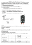
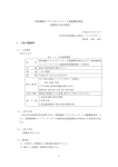
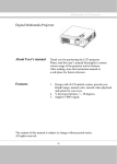
1
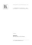
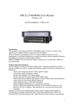
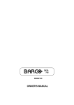
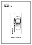
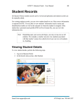
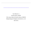
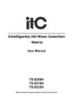
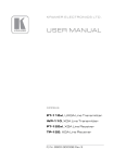
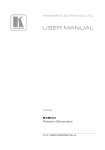
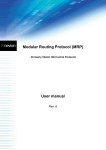
Professional HD Matrix Switch
User Manual
HD Matrix of HDMI series
HD Matrix of DVI series
HD Matrix of HVD series with Multiple Interfaces
Before using this system, please read this user manual thoroughly
Professional HD Matrix Switch - User Manual
PROFESSIONAL CROSSPOINT SERIES
! Guidance for Safe Operation
For ensuring the reliable performance of the equipment and the safety of the users, please follow
below guidance when installing, using or maintaining the equipment:
The system must has well grounding. Otherwise, there will be not only bad performance or
physical damage of the equipment, but also dangers for people due to electric leakage. The
ultimate grounding point of the matrix switch of HDMI, DVI and HVD series should be the
genuine earth. And the grounding resistance should be less than 1Ω.
It’s forbidden to change the original design of the product. No revision is allowed for the
mechanical and electrical design of the product. Additional components are not allowed also.
Otherwise, the manufacturer won’t be liable for any consequences caused by such changes.
Please do not use two-pin plug. Please make sure the power supply is AC 110V 60Hz.
As there are components inside with high voltage AC, please do not open the shell by
yourself to avoid electric shock.
Please do not put the equipment at place where the temperature is not in accordance with the
specification.
As the power supply will get heat when working, it’s a must to keep well ventilation at the
working location to avoid physical damage caused by overheat.
Please turn off the power switch of the equipment, if it’s rainy and humid or the equipment
will be idle for a long time.
It’s a must to take off the power plug of the equipment from the AC socket before follow
operations:
A. Disassemble or re-assemble any component of the equipment.
B.Disconnect or re-connect any electric plug or other connector.
Before permitted by professionals, please do not try to open the shell of the equipment and
repair the equipment by yourself, as it may cause accidents or further damage to the equipment.
Please do not have any chemicals (solid or liquid) touching or nearing the equipment.
1
Professional HD Matrix Switch - User Manual
PROFESSIONAL CROSSPOINT SERIES
Contents
I. Description of the HDMI/DVI/HVD HD Matrix System.....................................................................................3
1.1 About the Matrix Switch..........................................................................................................................3
1.2 The classification of the matrix systems..................................................................................................3
II. Packing Description of the Matrix System.......................................................................................................... 4
III. Installation of the Main Body of the Matrix.......................................................................................................4
IV. Sketch of Front and Rear Panel...........................................................................................................................5
Sketch of the interfaces on rear panel of HDMI0808.............................................................................. 5
Sketch of the interfaces on rear panel of HDMI1616.............................................................................. 5
Sketch of the interfaces on rear panel of DVI0808.................................................................................. 5
Sketch of the interfaces on rear panel of DVI1616.................................................................................. 6
V. Connection between the Matrix and Auxiliary Equipment..................................................................................6
5.1 Description of the input and output interfaces........................................................................................ 6
5.2 RS-232 communication port and connecting method............................................................................. 6
5.2.1 Connect matrix via network interface.......................................................................................... 6
5.2.2 Connect matrix with controlling PC.............................................................................................7
5.3 Connecting method for HD Matrix Switch............................................................................................. 7
5.4 Description of the structure of the plug-in type HD matrix.................................................................... 8
VI. Instructions of the Control Panel........................................................................................................................ 8
6.1 Description of the functions of the buttons on front panel......................................................................8
6.2 Operational demonstration.......................................................................................................................9
VII. Instructions of Remote Controller.................................................................................................................10
8.1. Instructions of software installation:..................................................................................................... 11
8.4 Function instructions of the software..................................................................................................... 11
8.5 Function instructions of the main operating interface....................................................................12
8.6 Further settings for automatic switching:....................................................................................... 12
IX. Communication Protocol and Command Codes............................................................................................ 13
9.1 RS232 communication protocol..................................................................................................................... 13
X. Technical Parameters of the Matrix System.................................................................................................... 15
10.1 Technical parameters:................................................................................................................................... 15
10.2 Specification and weight of the production line...........................................................................................16
XI. Common Faults and Maintenance.................................................................................................................. 17
Instructions of the User Manual............................................................................................................................18
2
Professional HD Matrix Switch - User Manual
PROFESSIONAL CROSSPOINT SERIES
I. Description of the HDMI/DVI/HVD HD Matrix
System
1.1 About the Matrix Switch
The HDMI/DVI HD Matrix Switch is a professional matrix switching equipment with
high-performance for switching HD audio and video signals. It supports input and output of HD video
signals (HDMI/DVI/HVD) and balanced/unbalanced audio signals. The product is designed for
applications such as broadcasting and TV project, multimedia conference hall, display engineering with
large screen, TV teaching, command and control center, etc. As approved by successful deployments in
demanding applications such as military, power grid, traffic, public security, etc, the device features
stable performance and good quality.
The good quality of the HDMI/DVI/HVD HD Matrix Switch is derived from our profound
technology heritages. For assuring the good quality, we have adopted the best chips for the switches and
cautiously designed every detail of the circle. As per strict test, the HDMI/DVI/HVD Switch features
4.5G bandwidth and supporting 1080p/720p HD video signal, which can be applied in various
demanding applications.
The HDMI/DVI HD Matrix Switch provides convenient man-machine interfaces for the users. The
HDMI/DVI/HVD HD Matrix Switch has monochrome or color LCD for Chinese information, RS232
communication interface, RJ45 networking control interface (optional), protection for power failure and
special control software. Up to 100 user-defined scenarios can be stored and read. The matrix switch can
cooperate with computer, remote control system or various remote control equipment (e.g., central
control systems). The system has a set of commands for serial port communication which is compatible
with popular matrices.
This user manual is applicable for all matrix switches of the mentioned series. Slight difference
may exist as the matrices are of different scales.
1.2 The classification of the matrix systems
Based on the different applications and demands of different users, the matrix systems are classified
as below models:
Technical Parameters
Model
Input
Output
interface
number
interface
RS232
LCD panel
interface
Panel-controlled
infrared
number
Case type
remote
plug-in
card
controller
availab
le
(Yes/N
o)
DVI-404
4
4/8
Yes
Yes
Yes
1.5U
No
DVI-8 series
8
4/8
Yes
Yes
Yes
2U
No
DVI-16 series
16
4/8/16
Yes
Yes
Yes
2U
No
3
Professional HD Matrix Switch - User Manual
PROFESSIONAL CROSSPOINT SERIES
DVI-24 series
24
4/8/16/24
Yes
Yes
Yes
6U
Yes
DVI-32 series
32
4/8/16/24/36
Yes
Yes
Yes
6U
Yes
HDMI-404
4
4
Yes
Yes
Yes
1.5U
No
HDMI-8 series
8
4/8
Yes
Yes
Yes
2U
No
HDMI-16 series
16
4/8/16
Yes
Yes
Yes
2U
No
HDMI-24 series
24
4/8/16/24/36
Yes
Yes
Yes
6U
Yes
HDMI-36 series
36
4/8/16/24/32/3
6
Yes
Yes
Yes
6U
Yes
HVD-24 series
24
8/16/24/32/36
Yes
Yes
Yes
6U
Yes
HVD-36 series
24
8/16/24/32/36
Yes
Yes
Yes
6U
Yes
Remarks: HVD series with multiple interfaces can accept video signals of different formats (HDMI, DVI, VGA
(with audio signal), AV, SDI and Color Component) at the same time, while the output format is unified as DVI
and HDMI. The number of input and output channels could be customized by inserting different cards for input
and output according to the requirements of the customers. The maximum channel number of input and output
channel is 36 respectively. Each card can provide 4 channels, while 18 cards in total are supportable for input
and output.
II. Packing Description of the Matrix System
Main body of the matrix
RS232 communication cable
Power cord
Disk of test and application software for the matrix
User manual and quality certificate for the equipment
III. Installation of the Main Body of the Matrix
The main body of the matrix adopts a complete metal case as shell, which can be deployed nearby
other equipment.
4
Professional HD Matrix Switch - User Manual
PROFESSIONAL CROSSPOINT SERIES
Additionally, standard installing brackets will be provided for the main body of the matrix. The user
can install the matrix on standard 19” equipment cabinet.
IV. Sketch of Front and Rear Panel
4.1 Sketch of the panels
Figure 4-1
Figure 4-2
Rear panel of the case(HDMI0404)
Front and rear panel of the case(HDMI/DVI-8/16)
Sketch of the interfaces on rear panel of HDMI0808
Sketch of the interfaces on rear panel of HDMI1616
5
Professional HD Matrix Switch - User Manual
PROFESSIONAL CROSSPOINT SERIES
Sketch of the interfaces on rear panel of DVI0808
Sketch of the interfaces on rear panel of DVI1616
V. Connection between the Matrix and Auxiliary Equipment
5.1 Description of the input and output interfaces
According to the model of the matrix,
HDMI Matrix (with 1.5U case): There are 4 interfaces for input and output respectively, which are
compatible with HDMI 1.3.
HDMI Matrix (with 2U case): There are 4, 8 or 16 interfaces for input and output respectively,
which are compatible with HDMI 1.3.
DVI Matrix (with 2U case): There are 4, 8 or 16 interfaces for input and output respectively, which
are compatible with DVI 1.3.
HVD Matrix: The input and output interfaces are HDMI and DVI/VGA ports on the card (each
card has 4 interface). The maximum number of interfaces of a certain type is 36.
5.2 RS-232 communication port and connecting method
All the matrices have standard RS-232 serial communication port (Ethernet port is optional), which
allows customers remotely control the system via various control systems or Ethernet, as an additional
operating method from front panel operation.
Connecting method: cross connection with PC (pin connecting method: 2-3, 3-2, 5-5)
RS-232 port is a 9-pin connector. The pin definition is as blow:
Pin No
Definition
Description
1
N/u
null
2
Tx
Receive data
3
Rx
Send data
6
Professional HD Matrix Switch - User Manual
4
5
6
7
8
9
5.2.1
PROFESSIONAL CROSSPOINT SERIES
N/u
Gnd
N/u
N/u
N/u
N/u
Null
Common grounding
Null
Null
Null
Null
Connect matrix via network interface
The matrix could be controlled via LAN by TCP/IP network.
5.2.2
Connect matrix with controlling PC
Using RS-232 cable to connect the serial
communication port of the PC (COM1 or COM2) with
the RS-232 communication port of the matrix. Then the
matrix could be controlled by the PC after installed the
control software.
The users can use the attached software as the PC
control software. They can also compile their own
control software according to the file of
“Communication Protocol and Command Codes”.
Figure 5-1
Connect the matrix with PC
5.3 Connecting method for HD Matrix Switch
1. There are different numbers of input and output connectors for HDMI/DVI/HVD HD Matrix
Systems of different models. The users can use them to connect the matrix with various HD display
equipment which has HDMI interface such as HD DVD player, HD camera, laptop, etc. The output
connector can be used to connect HD display terminals such as large screen projector, joint screen, etc.
(Remarks: If there is any change for the equipment, please connect the manufacturer)
7
Professional HD Matrix Switch - User Manual
PROFESSIONAL CROSSPOINT SERIES
Figure 5-2 Wiring diagram of HD Matrix System
5.4 Description of the structure of the plug-in type HD matrix
The plug-in type HD matrix is composed by two major parts: the case and the plug-in card.
1. The cards are classified as input card, output card, control card and power supply card.
The input cards include: DVI input card, HDMI input card, VGA card with audio, SDI card, Color
component card, and AV card.
The output cards include: DVI output card, HDMI output card, and VGA output card.
VI. Instructions of the Control Panel
6.1
Description of the functions of the buttons on front panel
”Function button”+”input channel”+”output channel”+”Enter”, here:
“Function button” include:
MENU: Press MENU button once is for switching audios or videos.
FUN:
Function button, for inquiring ID, switching status, etc.
SAVE:
Scenario setting.
RECALL:
Recall scenario
CANCEL:
Clear
ENTER:
Confirm button
8
Professional HD Matrix Switch - User Manual
F1:
PROFESSIONAL CROSSPOINT SERIES
Shortcut button
“Output channel”
The channel on which there is the signal source needs to be switched. It is indicated by number buttons on the
panel “0-9”, “10+”, “20+”, “30+”.
“Input channel”
The channel on which there is the signal source needs to be switched. It is indicated by number buttons on the
panel “0-9”, “10+”, “20+”, “30+”.
“Enter” for confirming the operation
Take matrix with 32 channels as sample:
Example 1: to switch audio/video signal from input channel 6 to output channel 8, the operation is as below:
“MENU”+“6”+“8”+“Enter”
Example 2:
to switch audio/video signal from input channel 10 to output channel 8, the operation is as below:
“MENU”+“10+”+“0”+“8”+“Enter”
Example 3: to switch audio/video signal from input channel 32 to output channel 8, the operation is as below:
“MENU”+“30+”+“2”+“8”+“Enter”
3.2 FUN: status inquiry, to inquire the current ID or current output and input status.
3.3 SAVE: to save current status. There is F1 storage unit,
For example: to save current status to F1, the operation is as below:
“SAVE”+“F1”+“Enter”
3.4 RECALL: Invoking
For example: to recall status saved in F1 as current status, the operation is as below:
“RECALL”+“F11”+“Enter”
3.5 CANCEL button
The button operation could be cleared by “CANCEL” button if there is any error for the input/output channel. Then input
the right input/output channel number.
6.2 Operational demonstration
Example 1: To switch signal of input channel 1 to output channel 3 (panel operation)
1. Press “MENU”
1
2
3
4
2
3
4
2. Press input channel number “1”
3. Press output channel number “3”
Display: signals on input channel 1 is switched to output channel 3
9
Professional HD Matrix Switch - User Manual
PROFESSIONAL CROSSPOINT SERIES
Example 2: To switch signal of input channel 10 to output channel 21 (panel operation)
1. Button operation for input channel number 10: 10+, 0
2.Button operation for output channel number 21: 20+, 1
Example 3: To switch signal of input channel 1 to all the output channels (panel operation)
1. Press “MENU”
1
2
3
4
2. Press input channel number “1”
3. Press “0”, then press “Enter”
10
Professional HD Matrix Switch - User Manual
PROFESSIONAL CROSSPOINT SERIES
VII. Instructions of Remote Controller
Instructions of button operation:
The matrix system can be controlled by remote controller for fast
switch. The function of each button is the same as which on the panel
(Please refer to “Instructions of Control Panel” for the detailed function
description of the buttons).
This remote controller is applicable for HDMI, DVI and HVD matrix.
The “Function Button” include:
AV: To switch audio and video signals at the same time
HD:switching trigger (same function as MENU on panel)
A: switch audio signal only
“1、2、3……”: To select output and input channel
“CANCEL”: to cancel the operation
“ENTER”: means to execute the button operation
“F1.....”: shortcut button
The standard operation is same as the panel operation
“0” means switch signal to all the output channels
VIII. Select the Language (Chinese/English)
8.1. Instructions of software installation:
Running environment of the software:
Window98/2000/NT/XP
Available memory is larger than 32M
Available disk space is larger than 10M
CD-ROM1
One serial communication port available at least
8.2.Install the control software
The attached disk with the matrix contains test and application software. The users can use the software to
11
Professional HD Matrix Switch - User Manual
PROFESSIONAL CROSSPOINT SERIES
control the matrix.
Put the attached disk into the CD driver of the PC, then run the EXE file:
X:\Matrix software \SETUP.EXE
Then the software will be installed.
8.3 Launch the software
First, power off the matrix and the PC, then connect the RS232 interfaces of the matrix and the PC with
communication cable (an attachment of the matrix);
Power on the matrix and the PC;
On the controlling PC, click in sequences “Start”
“Programs”
“Project”
Then the control software will be launched. The matching status of the matrix will be displayed after set
the serial port, matrix ID and matrix type.
8.4 Function instructions of the software
According to actual demand, the operating method could be set as automatic switch, keyboard
control, etc. Before setting the equipment type, please set the serial port of the PC and the matrix ID
(default ID is 00).
Main operating interface is as below:
Figure 0-1
User interface of the “setup” segment of control software
8.5 Function instructions of the main operating interface
Block for input/output channel: for selecting channels. Click numbers to select the channels need to
12
Professional HD Matrix Switch - User Manual
PROFESSIONAL CROSSPOINT SERIES
be switched.
Click the number icon directly for input number 1-9. If the number is larger than 9, please do as
following example. Example: to switch signal of input channel 36 to output channel 32, click “30+” and “6” to
set the input channel, then click “30+” and “2” to set the output channel, thus the signal will be switched
accordingly.
In right block, a circulating display could be set by directly selecting the start channel and end
channel, which can appoint one of the screens to display images of selected channels in turns with a regular
time interval.
8.6 Further settings for automatic switching:
Figure 0-2
User interface of “Automatic Switching Mode” segment of control software
Set the time interval of the automatic switching: set the switching time interval according to the
actual demand.
OUTPUT: Select the output screen. Select the screen according to the actual demand, then as shown
as above picture, select input channel number 1, 3, 4, 5, 7, 9, 11, 13,
17 first, then confirm the operation for automatic switching. Few
output channels can be selected for different input signal sources.
Allocating/switching mode: Allocating mode -- After selected input channel, then allocate its signal
to few output channels by clicking according icons in output block.
Switching mode -- After selected output channel, then select different input signals
in input block to the selected output channel.
13
Professional HD Matrix Switch - User Manual
PROFESSIONAL CROSSPOINT SERIES
IX. Communication Protocol and Command
Codes
9.1 RS232 communication protocol
Communication format: 1 start bit, 8 data bit, 1 stop bit, no no parity bit
Baud rate:9600Bps
Communication mode: Asynchronous half-duplex serial communication
Overview: All the DVI matrix, HDMI matrix and Audio/Video matrix have RS232 control interfaces which can be cascading
connected. They can be controlled by the RS232 interface of one PC or central control device with same protocol. The matrices
can be distinguished from each other by the head and the ID code.
Command format:
Head
Device ID
Command String
Data 1
Data 2
End String
PV
00-99
CMD
DATA1
DATA2
NT
Supported command list:
Command
Data 1
Data 2
Description
Input channel
Output channel
Switch the video and audio at the
number
number
same time
Input channel
Output channel
Switch the audio
number
number
Input channel
Output channel
number
number
00
Output channel
Inquire the status of appointed output
number
channel
00
Inquire the status of all output
String
SW
SA
SV
VW
VW
00
Switch the video
channel
SF
preset status number
00
Save current status in appointed
preset storage unit
RF
preset status number
00
Resume the appointed preset status
ID
Appointed ID
00
Change the ID code of the device to
the appointed ID
Expanded commands:
Command format:
Head
Device ID
Command
Data 1
string
14
Data 2
Data 3
Professional HD Matrix Switch - User Manual
PV
00-99
Comman
CMD
PROFESSIONAL CROSSPOINT SERIES
DATA1
DATA2
DATA3
Data 1
Data 2
Data 3
Description
Input channel
Initial output channel
Final output channel
Switch few channels
number
number
number
of video and audio at
d string
MW
the same time
MA
Input channel
Initial output channel
Final output channel
Switch few channels
number
number
number
of video and audio at
the same time
MV
Input channel
Initial output channel
Final output channel
Switch few channels
number
number
number
of video and audio at
the same time
Head:
PV: refers to DVI and HDMI matrix
Input channel number: 01 - the largest input channel number. It refers to actual input channel.
00: Close the appointed output channel.
>the largest input channel number: Invalid command, an error message will be returned.
Output channel number: 01 - the largest output channel number. It refers to the actual output channel.
00: Switch signals on appointed input channel to all the output channels.
>the largest output channel number: Invalid command, an error message will be returned.
Preset status number: 01 - 15. The device can save 15 preset statuses which can store video and audio at the same time.
Device ID: 00. It’s common ID for all the devices. When two or more devices are controlled by the same serial port, please do not
use this ID. If the ID of current device is unknown, connect this device with PC via serial port alone, then using
the common ID (00) to change the ID of this device to appointed ID.
01~99: Valid ID number for the device.
Appointed ID: 01 - 99.
Returned data from the device: Except VW (Inquiring status) command, all the correct commands will get returned message
“OK” from the device. In case the command is wrong, there will be a returned message “Err”;
DVI/HDMI matrix: PV)+input channel number+output channel number+video input channel of the 1st output
channel+audio input channel of the 1st output channel+video input channel of 2nd output channel+audio input
channel of 2nd output channel+......+video input channel of the maximum output channel+audio input channel
of the maximum output channel+OK.
If the ID code of one DVI/HDMI matrix is 08, to switch the signal of input channel 2 to output channel 5, the command is
PV08SV0205NT. For one DVI/HDMI matrix with ID code 26, to switch the signal of input channel 5 to output channel 1-9, the
command is PV26SV050109. This is a command to switch the signal of one input channel to several output channels. To switch
the signal of input channel 3 to all the output channels, the command is PV26SV0300NT.
15
Professional HD Matrix Switch - User Manual
PROFESSIONAL CROSSPOINT SERIES
X. Technical Parameters of the Matrix System
10.1 Technical parameters:
Video
Protocol
HDCP 1.3 protocol and HDMI 1.3 protocol are supported, compatible with DVI 1.0
protocol.
Gain
0 dB
Pixel Bandwidth
165MHz, 全数字 full-digital
Interface bandwidth 2.25Gbps, full-digital
Maximum resolution Normal-PC:1600x1200@60_24bit, HDPC: 1920x1200P@ 60_24bit,
HDTV:1920x1080P@60_36bit
Clock dither
<0.15 Tbit
Rise-time
<0.3Tbit (20%--80%)
Fall time
<0.3Tbit (20%--80%)
Maximum delay of
5nS(±1nS)
transfer
Video input
Switch speed
200 ns( Maximum time)
Signal type
HDMI-A full-digital T.M.D.S signal as specified in HDMI 1.3 standard. .
Connector
HDMI-A type, 19 pins, female connector
Signal strength
T.M.D.S +/- 0.4Vpp
Min/Max electrical
T.M.D.S 2.9V/3.3V
level
Input EDID
Standard EDID
Impedance
<75Ω
Maximum DC biased 15mV
offset
Suggested maximum Less than 20m for resolution of 1920x1200@60Hz (Approved HDMI cables are
length of the input
recommended, such as the cable of Molex TM)
cable
Video output Connector
Min/Max electrical
HDMI connector, 19 pins, female connector
T.M.D.S. 2.9V/3.3V
level
Impedance
<75Ω
Suggested maximum Less than 15m for resolution of 1920x1200@60Hz (Approved HDMI cables are
length of the output
recommended, such as the cable of Molex TM)
16
Professional HD Matrix Switch - User Manual
PROFESSIONAL CROSSPOINT SERIES
cable
RS232
RS232IN
RS232 male connector (connecting method: 2--3, 3--2, 5--5, isolate other pins)
RS232OUT
RS232 male connector (connecting method: 2-2, 3-3,5--5, isolate other pins)
Specification Power supply /power 100VAC ~ 240VAC, 50/60 Hz, standard adaptive power supply; Power: determined by the
of the device
size of the case and the channel numbers of the equipment
Temperature/
Storage and using temperature:
-20°~ +70°C; Humidity:10%~90%
Humidity
Specification of the
Standard case: 1.5U,2U,6U; Weight: determined by the size of the case and the channel
case/Weight
numbers of the equipment.
10.2 Specification and weight of the production line
Specification
of
Volume
Package volume
Net weight
Gross weight
480mmX265mmX47mm
520mmX340mmX120mm
3kg
4kg
480mmx 310mm x90mm
565mmX455mmX195mm
6kg
8kg
480mmx 310cmm x90mm
565mmX455mmX195mm
8kg
10kg
-
-
-
-
the matrix
4 channels for
input and output
respectively
8 channels for
input and output
16 channels for
input and output
36 channels for
input and output
XI. Common Faults and Maintenance
1)
2)
3)
When there is double image output by the display device connected with the matrix, for example, double
image from the projector, generally it’s not caused by the matrix.
A. The projector may not be correctly set or the cable is disqualified. Please adjust the projector or
change the cable.
B. Signal attenuation caused by long cable. Please add a signal driver for long cable.
C. Connected with heavy current.
If there is color missing or no video signal, the video connector may be poorly contacted or disconnected.
When the remote controller loses the control for the matrix:
A. The battery is run out of power. Please replace with new battery.
17
Professional HD Matrix Switch - User Manual
PROFESSIONAL CROSSPOINT SERIES
B. The remote controller is broken, please repair it.
4) When the serial port (generally it’s the serial port of the PC) is failed to control the matrix, please check if
the preset communication port of the software is correct, and if the communication port of the PC is of
good condition.
5) When there is no image output after switching,
A. Please check if there is signal at the input port. (Using an oscilloscope or universal meter to check) if
there is no signal, the reason may be the wire is broken or the connector is loosing. Please replace the
connection cable.
B. Please check if there is signal at the output port. (Using an oscilloscope or universal meter to check)
if there is no signal, the reason may be the wire is broken or the connector is loosing. Please replace
the connection cable.
C. Please check if the output port number is in accordance with the controlled one.
D. If the reason is not any one of the above, the matrix may has internal fault, please send it to
professionals for repair.
6) If there is not output on the LCD, and it’s failed to respond to command, please check the power supply,
and check if the fuse is burned.
7) If the output images are interfered, please check if there is well grounding for the input and output
devices.
8) If there are no signal input or output from some ports, it may be caused by bad contact or ports been
burned. For plug-in type matrix, please just replace the cards, then debugging again.
9) If there is screen mess, the reason may be the overlarge resolution or frequency.
10) If you felt strong static electricity when pull out or plug in the audio/video connectors, it indicates that the
device is not well grounded. Please correctly ground the matrix, otherwise, the matrix has danger of
damage by static electricity, and it won’t be able to meet the designed lifetime as well.
11) If there is output on the LCD and returned message from the communication port, but no image or audio
output,
A. The audio/video connector is loosing, please replace it.
B. There is short out in the wire, please replace the wire.
C. The wire is broken, please replace it.
If the matrix couldn’t respond to commands sent from panel operation, communication port or remote
controller, it may be broken, please send it to professionals for repair.
18
Professional HD Matrix Switch - User Manual
PROFESSIONAL CROSSPOINT SERIES
Instructions of the User Manual
The “User Manual for HD Matrix Switch” is an operational guidance for the users. Due to continuous
upgrade of the product, the actual operation for the matrices may has some differences from this user manual,
for which we will give written explanation based on the actual situation, and it’s not a mistake or omission.
For other information, please contact us directly or the dealers nearby.
All rights of the “User Manual for HD Matrix Switch” are reserved. Without our permit, no organization
or personal is allowed to use full or part of this manual for commercial purpose.
19