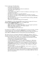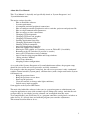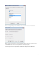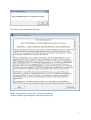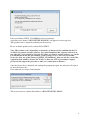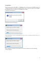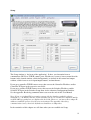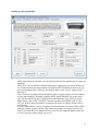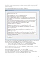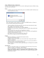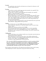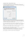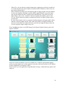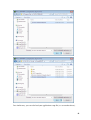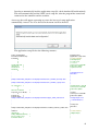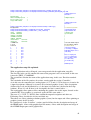
1
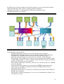
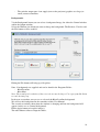
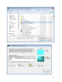
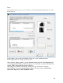
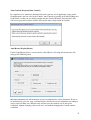
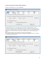
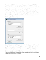
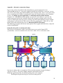
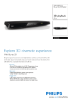
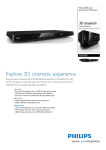
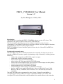
FHCS_CV804H404 User Manual
Version 1.07
By Frits Handgraaf, 15-May-2013
Introduction.
This document is describing the FHCS_CV804H404 software version 1.07 release. This
manual may not apply to earlier or later releases of the software.
The User manual is providing an overview of what is required in terms of system
requirements. It will further describe how to install the software, describe supported functions,
the graphical user interface and the program features.
FHCS_CV80H404 is licensed software against a license key fee. Contact ILS or FHCS for
price-information.
Product and program features.
The CAV-802 is a so called ‘controller/switcher/scaler’ originally developed by Creator to
provide an SPRO A/V product, capable of performing a range of functions, including (but not
limited to):
- switch video (composite) and PC (VGA) signals to output
- switch audio signals from input to output
- upscale video signals to VGA output signals
- upscale video and VGA input signals to DVI (HD) output
- control audio and microphone input signals to master volume output (including Mute)
- control relays for (motorized) attached equipment
- control attached devices via IR (infra red) control
- control intelligent attached devices via an RS232 connection
- interface with Creator supplied Touch Panels, either via CR-Link (Creator’s Link
Protocol), CR-Net, or Ethernet. These interfaces are 1 direction only (towards the
controller).
The Spro CAV-802 can be programmed by using Creator’s Control System Builder (a
development tool running on PC) and Creator’s Touch Panel Builder (also on PC). The
developed GUI can be downloaded to the Touch Panel, the control software to the controller.
1
Features of the Spro CAV-802 includes:
- 4 video inputs (composite video)
- 4 PC inputs (VGA, sub-D 15 pin)
- 8 audio inputs (Euroblock/Phoenix, balanced or unbalanced)
- 3 PC outputs (VGA, sub-D 15 pin)
- 1 DVI-D output
- 4 audio outputs (Euroblock/Phoenix, balanced or unbalanced). Audio output 1 is also
controlling master volume
- Switching any A/V input port to any A/V output port
- Up-scaling any video input to 800*600, 1024*768 or 1280*1024 VGA output
- Up-scaling any video input to a range of DVI-D outputs (including 1920*1080 HD) to
the DVI-D output port
- Up-scaling any PC input (VGA) to a range of DVI-D outputs (including 1920*1080
HD) to the DVI-D output port
- 3 RS232 ports supporting/controlling attached equipment.
The Pt-HDMI0404 is a high bandwidth HDMI switcher originally developed by Creator to
provide a matrix switcher with 4 HDMI inputs and 4 HDMI outputs.
Features of the Pt-HDMI0404 includes:
- Supports HDMI 1.3, HDCP 1.3 and DVI 1.0
- Supports up to 30 meter of HDMI cabling without extra signal support requirements
- HDTV (1920*1080p) and high PC (1920*1200) resolutions
- 2 RS232 Comm ports for PC control
- 1 LAN TCP/IP port for PC network control
Frits Handgraaf CS (FHCS), in cooperation with Intelligent Lectern Systems (ILS), developed
integration of the Spro CAV-802 and the Pt-HDMI0404 in an environment containing a
personal computer (PC) with an attached touch monitor (either direct touch, pen(cil) based or
other). FHCS_CV802H0404 will also just work with a PC and attached USB mouse.
The software will run on any normal (standard) PC with XP, Vista, Windows7 (Win7) or
Windows8 operating system. The Spro CAV-802 and Pt-HDMI0404 can be pre-programmed
to interface with the PC and the software, via a networked connection LAN (TCP/IP):
- The pre-programmed Spro CAV-802 will communicate uni-directional (CAV-802
listening only) over the CAV-802 network interface.
- A network adapter (10/100 MB) in the PC is required.
- CAV-802 default IP address is 192.168.1.200, TCP listening port is 1000, subnet
mask 255.255.255.0, default gateway 192.168.1.1. PC IP address may need to be
adapted (though CAV-802 IP address can be changed too via the Internet browser).
- Pt-HDMI0404 default IP address is 192.168.0.2, TCP listening port is 5000, subnet
mask 255.255.255.0, default gateway 192.168.0.1. These settings can be adapted
within this program.
- To connect both the CAV-802 and Pt-HDMI0404, a hub or router is required (not
supplied) and addresses have to be adapted.
- Further supported peripherals are the NEC PX700W projector (over TCP/IP or RS232
direct from the PC), the Da-Lite Contour Electrol (via a controller relay), the Projector
Drop Mechanism PD3 (via RS232) from the PC and the Philips BDP3380-12 Blu-ray
player (via controller IR).
2
About this User Manual.
This ‘User Manual’ is basically and specifically aimed at ‘System Integrators’ and
‘System/Administrators’.
The major sections describe:
- How to Install the software.
- System requirements.
- Assumptions on initial peripheral connections.
- How to configure attached peripherals such as switcher, projector and projector lift.
- How to adapt communication parameters.
- How to connect or close connections.
- Changing GUI backgrounds.
- Changing GUI Icons and graphics.
- Changing GUI button colors.
- Loading Application Setup files.
- Changing Application Setup files.
- Showing Learned commands.
- Auto-load Application Setup files.
- Protection against Setup changes.
- Moving the GUI window to a secondary screen or Tablet-PC (if available).
- Returning to the GUI window (if preview is at stake).
- Auto-scale GUI window to max resolution.
- Auto-Control to skip program Main and Setup windows.
- ‘Debug window’ Monitor.
- Other Setup submenus.
- Adapting to other configurations.
As a result of the Systems Integrator or System/Administrator efforts, the program setup
should be clear to the end-user or presenter, and fully ‘automatic’.
For example, when the program is started up, the end-user or presenter is only ‘confronted’
with the Control window (System panel), and from there (with a single touch on the System
ON button) can:
- Bring the projector down.
- Bring the projector screen down.
- Power up the projector.
- Close the curtains (or change other light conditions).
- Switch source input to output.
Same applies to the System OFF button..
The main idea behind the software is that you (as system integrator or administrator) can
setup the application to your (with customer agreed) likings and settings. And that the enduser/presenter, by just simply pressing a button, can accomplish what they want.
To accomplish that, you do not have to (re-) program controllers, touch panels, switchers or
other devices. It’s already done and with this program you can make adjustments.
This manual describes how to do so…
3
Content:
Page:
Software installation.
Startup/Main.
Setup.
Setting up your application.
Backgrounds.
Icons.
Output.
Control.
Setup, additional settings and functions.
Setting Relay timing.
Configuring Projector.
Configuring Lift.
Configuring Switcher.
Saving and restoring your application setup.
The application setup file explained.
Learned list.
Explaining learned mode.
Hotkey Setup.
Returning FHCS GUI output.
Auto Control.
Auto Resize.
Selecting control window monitor.
Status.
Monitoring.
Setup conclusion.
Appendix : Alternative connection Setups.
Appendix : Projectors.
Appendix : Resolving communications issues.
Appendix : Changing network settings (CAV-802).
Conclusion.
5
9
11
12
14
16
17
19
26
28
29
31
32
38
42
43
44
45
45
47
47
48
49
50
51
52
55
57
58
60
4
Software installation.
Note: The equipment may have been shipped with the software already installed on the system
PC. If you received a newer version or an update, proceed as follows:
- remove the earlier version using start/control panel/remove software.
- Follow the instructions below
Once you have received the software (normally in the form of a ZIP file), Un-zip the file into
an empty folder. Then run setup.exe to start the installation.
The following form will pop-up:
Hit OK to proceed.
Next form will show up:
Left-mouse_Click the button to the left of ‘Click this button to install…’
Next form will be presented:
5
Select the Program Group under which you want to install the software. Hit Continue:
While copying required files, the setup program may discover that your system has a newer
version. In that case select Yes to keep the newer file on your system.
Once all required files are copied and the installation is complete, hit the OK button.
6
The License Agreement form will show:
Hit the I Agree button or enter Alt + A from the keyboard.
A form will show up showing the calculated product-code:
7
Like stated before, FHCS_CV804H404 is licensed software.
A product code, format ‘ABCD-EFGHIJ-KLMNOP’ will appear in a message box.
This product-code is required to obtain your license key.
Please, with this product-code, contact ILS or FHCS.
Note: The product code is depending on a number of characteristics embedded in the PC
on which you want to run this software. You can not duplicate this software and run it on
any other PC. So be careful to chose the PC where you want to run the software, e.g. on the
PC embedded with the ILS presentation system. Failure to do so will cost you another
license fee. But, one of the features of FHCS_CV804H404 is, that you can also control the
equipment from another (remote) PC (LAN), so that your ICT or presentation support
personnel can support the presenter or take over control from a distance…
Once the license-key is obtained and starting the program up again, the software will request
to enter the license key.
If not obtained yet, hit the Cancel button:
The license-key has a format like follows: ABCD-EFGH-IJKL-MNOP
8
Startup/Main.
When starting up first time, FHCS_CV804H404 will try to interrogate which RS232 ports are
available in your PC (to control a projector or other device) and try to connect over TCP/IP to
the controller and try to connect over TCP/IP to the switcher
An Initialize form appears:
The following forms will appear.
Note: It may take several seconds whether the device can be reached, specifically if there is a
connection error.
If the controller or switcher is not connected or can not be found over LAN, following
message appears:
9
The Main window will appear after:
Note: The build indication may be another date if the program was later adapted.
If an earlier connection was successfully made, the Control button would be enabled.
If not, hit the Setup button (or Alt + S) to go to the setup form.
In Setup you can define communication parameters and much more…
10
Setup.
The Setup window is ‘the heart of the application’. In here, you determine how to
communicate (RS232 or TCP/IP, comm. ports, IP addresses etcetera), how to name/describe
buttons in the control window, which background(s) to include in the control and output
window, which icons to use in input/output buttons, and much more…
If you got a controller TCP/IP connect error, then correct the Controller IP address and/or
Controller TCP port in the respective text fields.
If you got a switcher TCP/IP connect error, then correct the Switcher IP address and/or
Switcher TCP port in the Switcher Setup form via the submenu Configuration/Switcher.
See the appendix: Resolving communication issues near the end of this User Manual
Note: If you received an ILS presentation system with the hardware and this software
installed, (e.g. an ILS24), then the system should work as it is tested before shipment and the
used IP addresses and ports are displayed in the fields. However, you may want to adapt IP
addresses and TCP ports to fit with your environment. The appendix: Resolving
communication issues, shows the defaults used and how to adapt these.
In the remainder of this chapter we will show what you can establish via Setup.
11
Setting up your Application.
-
-
-
-
Under Application description, you can enter the title of your application, in your own
language.
Under Use, you can check or uncheck input ports, output ports and relays actually in
use. If not checked, the source buttons associated will be disabled, so that a user can
press them without effect. Here we un-checked input 1 thru 3 and 8, output 2 and 3
and relay 2.
Under Connected product you can define the label to appear on the associated button,
in your own language. Examples could be DVD, laptop, Main PC etc on the input
side. On the output side these could be labels like Projector, large LCD screen etc.
Under Name, you see the ‘standard’ Connected product description, such as CV1,
CV2 etc. If the Connected product description text fields are empty, Names will be
used instead.
If via the Icons button, icons are associated with the buttons, the button will be filled
with the selected graphic icon file. The connected product description will then be
moved to a label above the button. In Icons, you can also adapt the button colors for
several categories (input, output, relays etc).
12
By filling-in the Connected product text field descriptions, you can associate the hardware
input and output ports with ‘real-life’ attached product descriptions.
Obviously, this requires a well thought out architectural component setup.
The following image is an example:
From the image you can tell that:
- The Smart SDC280 is connected to the CV4 input port of the controller.
- The Internal PC VGA output port is connected to the controller VGA1 input port.
- The InFocus LiteshowIII is connected to the controller VGA2 input port.
- Notebook connected laptops are connected to the controller VGA3 input port.
- The controller VGA1 output port is connected to a side control panel, which could be
a 1200 * 800 resolution 12” (such as supplied with the ILS24) or an iPad or Samsung
Galaxy Tab. This panel serves as ‘preview’.
- The controller output port 4 (DVI-D) is connected to a switcher (in this case a HDMI
4 in 4 out switcher).
- The internal PC DVI output port is connected to the HDMI switcher input port 1,
which in turn (by default) is switching to the Wacom 2200 main LCD screen
(embedded with the ILS24).
- The switcher output port 2 is connected to a NEC projector (under control, RS232 or
TCP/IP, of this program).
- The Switcher’s input and output ports 3, are reserved to communicate with the Cisco
teleconference system.
13
-
The switcher output port 4 can supply (next to the projector) graphics to a large (or
small) connected monitor.
Backgrounds.
Via the Background button you can select a background image, for either the Control window
and/or the Output window.
Select the Window for which you want to change the background. The Remove, Unselect and
the File buttons will be enabled:
Hitting the File button will bring up a file picker.
Note: 2 backgrounds are supplied and can be found in the Programs Folder:
- BlueGreenSun
- Blue-Moss
Note: The actual pixel resolution of the screen in use may be larger. Use a program like Paint
to scale the image up.
In the next screenshots you can see we selected the BlueGreenSun background.
We will use this background in the remainder of this User Manual.
The second screenshots shows how the window is changing and how the background will
appear (in this case as Control background).
Hit the apply button to keep this image(s).
The other buttons allow to adapt the choice.
14
15
Icons.
Via the Icons button, you can select an Icon for each of the input and output ports, as well as
for the 4 relays:
In this window, you can also select Button Colors to set your own button colors.
Hit the Apply button for changes to go into effect.
Note: No Icons (images, photo’s, etc) are included with the software. Frits Handgraaf CS
over time has collected these via Internet access. As an end-user you may do the same. On
request, FHCS can provide the current collection.
Note: Images nor button icons may fit. You may have to scale them accordingly.
Note: PNG files can not be loaded with this software. You may want to translate these
images into bmp, jpeg or other compatible sources.
16
Output.
The Output button will bring up a choice between 2 other windows:
Resolution and OSD.
The Resolution and OSD window Tab allows to change a number of things.
Composite video (CV1 – CV4) can be changed to VGA output resolutions, ranging to
800*600, 1024*768 or 1280*1024. This basically means that you can up-scale CV1 – CV4 to
output VGA resolution to any of the 3 VGA output ports. Composite video input ports can
also be up-scaled to DVI output resolutions, to the DVI output port.
Under ‘Composite video to VGA output Resolution’, select your desired VGA output
resolution.
Under ‘DVI Output Resolution’ you can select any DVI-D output resolution on the Spro
CAV-802 up to 1920*1080 (HD 1080p), no matter what input source (4 * CV or 4 * VGA) is
selected. The DVI-D output resolution will be displayed in the Setup/Display/Status window.
Note: When shipped directly from the factory (factory default), the controller DVI-D output is
set to 1024 * 768. Make sure the output resolution setting is fitting your application.
DVI scaling permits to select 4:3 or 16:9 aspect ratio.
OSD duration determines how long the OSD menu overlay remains visible in seconds from
15 – 60. (In the controller, this is 15 seconds by default).
If you made any changes (in the example we set the DVI Output Resolution to 1280*800), hit
the Apply button. The program will then send the appropriate commands to the controller.
17
Note: The program will recognize which changes were made and will only send commands
affecting these changed settings. When executed by the controller successfully the
communication indicator (between the Setup and Apply buttons) will color dark green.
After hitting the DVI OSD Menu button, the OSD appears on the DVI output port. With the
navigation buttons (left – right) and the Enter button, you can adapt DVI settings straight in
the DVI OSD menu.
Note: A DVI connected monitor is required for this. The OSD menu will NOT appear on a
VGA connected monitor.
DVI Picture Settings.
DVI picture settings allow you to change DVI connected projector or monitor settings:
Picture mode allows to select predefined settings, affecting appearance.
Color Temperature affects the ‘white representation’.
Changing Brightness, Contrast, Red, Green and Blue will have another effect on the outcoming DVI picture.
You can all adjust this to your ‘liking’.
Note; The Blue-Moss background image is used as example in this documentation.
Note: Hitting the Defaults button will change back settings of the DVI output to factory
settings. These are STANDARD for Picture Mode, NORMAL for Color Temperature, 50 each
for Brightness, Contrast, RGB values, as shown in the screenshot. It will also restore OSD
and resolution settings, as shown under Resolution and OSD.
18
Control.
Hitting the Control button will bring up the major GUI (graphical user interface), the Control
window.
After making all adaptations in Setup, it will appear as follows:
The Control window will appear as shown above.
The top row command buttons each will show up a panel with additional command buttons.
When the control window appears first time, the System panel will show 4 buttons:
- The Exit program button will show a message (“are you sure.. “). If you answer Yes it
will save all relevant communication settings to registry, close all communication
channels and exit the program. Note: Exit will NOT Save your application setup,
including selected backgrounds, icons, button colors and button descriptions. How
to save your application Setup is explained later in this manual.
- The Setup button will hide the Control window and bring you back to the Setup
window.
- The System ON button will cause a number of events to happen, so that your system
and system environment is ready for use. It will:
o Show the Projector panel.
o Move the projector lift down (if not already).
o Move the projector screen down.
o Power On the projector (if not already).
o Close the curtains.
o Show the System panel again.
- The System OFF button will:
o Show the projector panel.
o Power Off the projector.
o Open the curtains.
19
o Move the projector screen up.
o Move the projector lift up.
o Show the System panel again.
All the required timing, e.g. for the projector lift, the screen, the projector to power on or lamp
cooling time (projector off) and curtains, is defined in the Setup window. More about that
later in this User Manual.
Hitting the Room panel will result into the Room panel becoming available:
Via the Room control panel you can adjust the room conditions manually (as opposed to the
automatic handling via System ON/OFF).
- Via the Relay1 button (here described as “Projector screen Da-lite”) you can move the
projectors screen up or down.
- Via the Relay3 button (here described as “Curtains up”) you can open de window
curtains. Note that an icon (graphics) was added and the description is now moved to
the label above the button.
- Via the Relay4 button the curtains are closed.
Note that Relay2 is not used (in Setup it was un-checked) and has no description nor an icon
(graphics) associated.
As with System ON/OF required timing, in this case defining how long a relay is closed
(active) before opening again, is done in Setup. We will explain later in this User Manual.
Also note that the panel background is the same as the Control window background and the
labeling of the command button has changed from a black to a blue color.
Hitting the Projector command button will bring up the Projector panel:
20
Just as within the control Room panel, within the Projector panel you can manually adapt the
projector condition and the projector lift, when not using the System panel ON/OFF.
Note: Some caution is required here ! If the projector is powered On or Off via the projector
remote control, (or other means) ,this software has no way of knowing this. If a remote
control for the projector is not used, the program will prohibit actions under certain
circumstances, see below.
-
-
-
Hitting the Proj ON button will result in sending a projector ON command to the
attached projector. Which command to send is defined in the Setup window (how to
do this and define the communication channel to use is described later in this User
Manual). If this application finds that the projector lift is not down yet (e.g. still in
ceiling mounted protected position), a warning message will appear and the power On
command is NOT sent.
Hitting the Proj OFF button will result in sending a projector OFF command. The
indicator between the Proj ON and Proj OFF buttons will blink (each second) for the
duration as required to power on or off, as defined in Setup.
The projector lift Down button will bring the projector down. The indicator above the
Lift label will blink each second.
The projector lift Up button will raise the projector to it’s upmost position.
The Stop button will stop lift movement.
In this application setup, the projector input source switching (done by this program) is
disabled, hence the buttons are disabled. The yellow indicator above the HDMI input source
indicates the projector input source is set to the HDMI input port. How to enable projector
input source switching and to define commands to do so is explained later in this User
Manual.
21
Hitting the Control window Source command button will bring up the Source switching
panel, as shown above.
On the left, the 8 controller/scaler/switcher (CV804) analog input sources are shown, which
are the 4 Composite Video input sources and the 4 VGA input sources.
On the right you see the 4 input sources to the HDMI switcher.
The yellow indicator next to the input sources buttons show which input sources are currently
selected. In this example this is the VGA1 input source of the controller/switcher/scaler
(Internal PC of the ILS24 presentation system) and the HDMI switcher input source 1, being
the DVI output of the internal PC. In this example, the other Composite Video input ports
(CV1 – CV3) are disabled, as well as the VGA4 input port.
The HDMI 2 input port is connected to the Philips BDP3380 Blu-ray player HDMI output,
HDMI input 3 to the Cisco Telepresence system and the HDMI input 4 is receiving the DVID output of the controller, just as the application architecture at the beginning of this User
Manual showed.
The application setup determined that the analog input (via the controller) is first ‘pre-viewed’
on the ILS24 12” (1280 * 800) side screen. By hitting the ‘> DVI-D’ button, the controller’s
analog input signal is directed to the controller’s DVI output port, including up-scaling
according to the output resolution as set in the Output window. This basically means that the
controller digital output is fed to the HDMI switcher port 4 input, as shown in the control
window.
All digital video is forwarded to the ‘digital preview screen’, which in this case in the ILS24
is the Wacom 2200. By selecting another HDMI switcher input source, the presenter will
therefore see the digital graphics on the ILS24 main screen. By hitting the ‘> HDMI Out’
button, the selected HDMI switcher input signal will be switched to ALL 4 HDMI output
ports, whether they are connected and/or powered on/off or not. In this way the presenter is
switching the ‘preview’ to the output peripherals, as he or she so desires…
22
By hitting the Blu-ray command button in the Control window, the Blu-ray control panel will
show up:
Note: The interaction with embedded video players like DVD or Blu-ray, is established via
one of the 4 IR control links (glass-fiber) outputs of the controller. The controller has to be
pre- programmed (firmware) to control the Blu-ray player of your liking. In this application,
the controller was pre- programmed to support the Philips BDP3380, over IR output port 1.
In this application software package we have defined 9 buttons for basic interaction.
The Previous button will go back to the ‘previous’ scene, the Next button will forward to the
next scene. The Pause button will pause the video so that you can take a break and explain
students something in between.
The Rewind and Forward buttons allow to go back or going forward in the video, up to as far
as you want. In order to ‘stop’ forwarding or rewinding, press the Pause button, and then Play
to show again.
The Stop button stops playing and shows the OSD (if monitor is connected). The Play button
will resume playing again.
The Power button is aimed to power on/off your connected video player. Only when Power is
off, the Eject button will eject the disk (pressing Play will bring it back in).
The above button ‘behavior’ description is based on my own experiences with the IR
programmed controller and the player. See the player User Manual for more details.
Note: Currently, in this version of this application program, the used text and icons
(graphics) are ‘hard’ defined (you can not change these). If you want other button
descriptions and/or icons, please contact ILS or FHCS.
Hitting the Control window GUI Volume button will show up the Volume control panel:
23
The embedded controller/switcher/scaler allows to control your volume settings.
If you hit the Master Volume up button, a yellow indicator will appear showing you last
brought the volume up, above the volume up button. The text field under the Master/Mute
button, will show the current volume setting (in a range from 0 – 10).
Same applies for the Mic volume control.
Note: The embedded controller can adjust volume settings by 1 adjustment ( +1 or -1 ) at a
time. Therefore, adjusting the volume control, may take some time before the new setting
appears in the text field.
If you hit the Mute button (both for Master and Microphone), the button background color
will turn red and the button caption will change to “Muted”. Also, the up/down buttons will
be disabled. Hit the ‘muted’ button again to un-mute, and you can adapt the volume settings
again.
Note: The controller only has Master Volume control over Audio output 1.
Note: The controller only has Mic control if a microphone is connected to the front of the
controller.
Above the Help button you see 4 communication indicators.
Initially, all 4 are black.
In the screenshot above, the C indicator (C for controller) is colored dark green, indicating a
successful connection has been made, a command has been sent and a response has been
received. The P indicator (P for projector) is colored light green, indicating the RS232
connection to the projector is ‘opened’ but no reply to a source switching command (HDMI
input) has been received back.
24
Note: While writing this documentation, we had no projector Lift (L) available, nor NEC
projector available.
When you hit the Help button, a help text window will appear:
The original Help.rtf file is distributed with the application package and can be found back in
the folder where you installed the application (typically Program Files\ILS).
If you want to write your own Help text (in your own or customer language) then:
- rename or copy Help.rtf to another name (e.g. Helporg.rtf) or to another folder
- use a text-editor like Word to change your text and save it as Help.rtf
Note: The application will only search for the Help.rtf in it’s application path. If not found
there you will receive a warning message.
In the bottom-right of the Control window, you can see a ‘Logo’.
For the time being this is a ‘hard coded’ logo for Frits Handgraaf CS (FHCS).
If you rather want your own dealer logo to appear here (or your end-user customer logo),
please contact ILS or FHCS and send in the bitmap or JPEG for display.
25
Setup, additional settings and functions.
In the top of the Setup form you have access to menu’s which provide means of further setting
up your system environment.
Extra.
- Available Comm will show which comm. ports are available in the PC, which ones are
used and which ones are free:
Note: The Controller and the Switcher are reached via TCP/IP. In this case Comm1 is
used to reach the attached projector from the PC.
-
Comm OpenDelay. Depending on the PC it may take some time before the comm.
port is opened. You can specify a delay here.
CommandDelay is the delay between sending commands.
ReadDelay is the delay before reading reply from the CAV802, swither and/or from
projector.
Load Setup will load a previously saved application setup file.
Autoload (when set) will automatically load (the last) previously stored application
setup file when the program is started.
Save Setup will save the current application setup to file.
Exit will leave Setup and return to the startup window.
Display.
- Debug On will bring up a communication monitor window.
- Debug Off will hide the monitor.
- Via Resize and the resize window you can determine how resizing of the Control
Window is performed.
- Monitors will show if a secondary monitor is attached. You can move the GUI to a
secondary monitor via the form which shows up.
- Status will bring up a window showing input/output port switching for the controller
and the switcher.
System reset.
- Soft reset will perform a power cycle, opening previous closed relays. You can use
Soft Reset to apply a new IP address (when changed).
- Hard reset will perform a controller total reset, closing all output channels (factory
default) and a Soft Reset. However, it will NOT perform a DVI factory reset (which
can be done in the Output window), NOR will it reset a changed TCP/IP parameter,
like IP address or Port.
26
Learned.
- If an application setup is loaded it will show the saved learned list. Otherwise it will
show the default learned list.
Program.
- In port allows to specify to which input port of the controller, the control PC VGA
output is connected. Default is 5 (VGA1).
- Out port allows to specify to which output port of the controller, the control PC
graphics is connected. Default is 1 (VGA1).
- Return Output shows current definition of In and Out ports.
- Hotkey/Control allows to specify a keyboard entry with which the control PC output
becomes visible again in cases an input channel is switched to the PC’s output port.
(Note: If the control PC output is not connected to the controller, you can ignore the
above settings). Hotkey/Setup allows to protect access to the Setup window if you
want to prevent Setup changes.
- By setting Auto control, the program when started will automatically come up with the
Control Window, skipping Main and Setup windows.
TCP/IP.
- State will show the state of the TCP/IP connection to the CAV802.
- Close will close the connection. Use this if the windows socket is in error or keeps
trying to connect.
- Connect can be used to (re-)connect to the CAV802.
- PC IP will show the IP address of the control PC. This is an aid in determining
whether the IP’s of PC and CAV802 and/o Projector, are in a compatible range.
- Local Port. Use this to change the PC TCP port number. This may be required to get
through a Firewall.
Configuration.
- Projector will bring up a new window in which you can determine connected projector
communication setup and commands.
- Relay timing allows to specify how long a relay is closed before opening again.
- Switcher will bring up a new window in which communication, button descriptions
and icons can be defined, for the HDMI0404 switcher.
- Lift allows to setup communications to the projector lift.
Note: In order for TCP/IP communication and IR out control to work, the CAV802
has to be ‘custom tailored programmed’. This release is supporting all embedded
functions and projector control directly from the PC. For additional functionality the
CAV802 programming has to be adapted/extended. Contact ILS/FHCS for further
information (IR codes and/or Projector codes will be required).
In the remainder of this manual we will explain the menu functions in more detail, starting
with configuring the switcher, the projector, the projector lift and relay timing.
27
Setting Relay timing. (Configuration/Relay timing).
Via Setup/Configuration/Relay timing you can specify the number of seconds a relay is
closed before opening again. An entry of 0 seconds will close the relay until manually opened
again (do this by hitting the relay button again).
When a relay is activated, it’s button color will turn green. Pressing it again will return the
defined relay color. If timing is set, the label above the relay button will start blinking in a 1
second session (on/off) until the specified time has passed. Timing can not be negative (<0)
and maximum setting can not exceed 65535 seconds.
Note: You can set fractional seconds, but this will be rounded off to the nearest integer.
Note: The relay timing will be stored in registry, but it will NOT be stored in your application
setup file. This is to prevent possible harm to electrical equipment in another application
setup.
Note: The Spro CAV-802 will NOT remember relay status when switched off. After a power
cycle, all relays are ‘open’. This program however will store the timing.
Under ‘Duration in seconds’, enter the number of seconds, for each relay, you want the relay
to be closed (activated) before opening again (de-activated).
Entering a value of 0 means that the relay is activated until manually (without timer) is
deactivated again. De-activation can always be done by hitting the relay button again.
The relay buttons are available in the Control window, in the Room panel.
28
Configuring Projector (Configuration/Projector).
Via the Setup/Configuration/Projector menu you can define communication parameters and
projector commands for a projector which is directly connected to the control PC (and this
program):
As you can see from the screenshot, there is a whole lot of parameters you can adapt. Let’s
start with the communication setup.
Under ‘Projector direct from PC’ you can select whether the projector is connected via a serial
RS232 connection, or via LAN or WiFi through TCP/IP. For this application RS232 is
default. The following parameters can be adapted:
- Comm port. Select which comm. port you want to use.
- Settings. Default is 38400,N,8,1 which stands for:
o Baudrate is 38400
o Parity is N, None
o Nr of data-bits is 8
o Nr of stop-bits is 1
29
-
-
o Note: If you change these settings, make sure the 3 comma’s are still there.
Trail. Projectors may require a trail character to recognize an end of a command (such
as Cr, Lf, CrLf or other). Select here. Note: You can also specify the trail character in
each of the command strings. In that case, specify None here.
Handshaking. Some projectors may require some kind of handshaking. Select the
required form of handshaking.
In the caption of the windows form you can see for which projector brand and model all of
these settings are predefined (in this case for the NEC PX700W).
If you rather want to connect over TCP/IP, select the TCP/IP option. The serial parameters
will now be disabled, the IP address and the TCP port fields will be enabled. Make sure the IP
address has a correct structure (with 3 points) and that both address and port are correct.
The PC IP address field will not be enabled, but shows in which group the projector is
expected (in this case 192.168.x.x). The Local PC port specifies the ‘outgoing’ TCP port to
the projector (in this case 0, which means any ‘free’ port). How to change this, e.g. how to get
through a possible Firewall with a fixed port, is specified later in this chapter.
Under ‘Projector source switching desired’ you can specify whether you want this program
also to control the projector’s inputs. Default is No. This basically means that the source
buttons in the Control window, in the Projector panel, are disabled. This also means that the
source switching command string fields are disabled.
Note: Caution, specifying No does not disable the projector Power On and Power OFF
fields.
In the ‘Power On/Off Timing in seconds’ fields you can specify how long it takes to power on
the projector (e.g. how long it takes for the lamp to get to full brightness) or to power down
(e.g. how long it takes for the lamp to cool down before powering down the projector).
Note: These timings are used in the Control window System panel for On/Off and in the
Projector panel for On/Off).
In the projector command string fields you can enter required commands for the specific
functions in ASCII, a combination of ASCII and Hex (specify Hex input with \x) or Hex only.
In this program (as stated before) support for the NEC PX700W was pre-defined. The NEC
protocol and documentation explains all commands in a Hex command structure.
So why do we allow to change the projector command strings ?
It may well be that the projector is temporarily replaced with another brand or model (e.g. in
case of repair) or that a total other projector is installed. Instead of requiring another version
of this program to (re-programming) you can adapt to the ‘new’ situation yourself. If help is
required, contact ILS or FHCS but consult the Projector chapter at the end of this manual first.
By hitting the Apply button, everything will be saved, whether or not you made any changes.
Hit the Setup button to leave the window, not applying anything.
In the menu (top of the window) you find:
- Name. Adapt the Brand and the model name if adapted for another projector.
- RS232. Check the status of a comm. connection, close the comm. connection or open
a comm. port.
- TCP/IP. Check the status, close a connection or establish a new connection. Via Local
Port you can specify a specific outgoing port, e.g. to go through an outgoing Firewall.
30
Configuring Lift (Configuration/Lift).
Via the Setup/Configuration/Lift menu you can define communication parameters for a
projector lift mechanism (elevation system) which is directly connected to the control PC (and
this program):
Note: In this version of the program, the software is ‘hard-coded’ to support the PD3 from
Projector Drop Mechanism (PDM) only.
If you require support for another elevation system, please contact ILS or FHCS.
The PD3 can only be controlled over a RS232 connection, hence the TCP/IP option (under
‘Projector Lift direct from PC via’) is disabled.
What you can adapt are the comm. port and the timing for the lift to come down and the
timing for the lift to go to it’s upmost (highest) position.
Under Comm port you can specify which comm. port to use. As comm. port 1 was assigned to
the projector, comm. port 2 is default.
Note: Warning, do not specify a port equal to another earlier assigned port.
In the timing fields you can specify how long it takes for the projector lift to get into desired
position. This timing will be used in the Control window in the System panel (ON/OF) and in
the Projector panel (Lift down/up). Hit the Apply button to apply changes.
31
Configuring Switcher (Configuration/Switcher).
Via the Setup/Configuration/Switcher menu you can define communication parameters,
button descriptions and icons for the connected switcher which is directly connected to the
control PC (and this program):
From the screenshot you can tell a successful connection to the switcher was not made after
program startup:
- The line under TCP/IP (Connect via frame) is dashed instead of solid.
- The Connect button is visible.
- The Set/Enquire function in the top menu is disabled.
Note: After checking the Status in the TCP/IP menu, you probably get a message like this:
If you do know the Switcher IP address and TCP port, change the fields accordingly. Defaults
are 192.168.0.2 and 5000. Adapt the control PC settings to reach the switcher, and re-connect.
Also see the Appendix: Resolving Communication issues.
Note: Once connected, you can change the IP address and/or port via Set/Enquire.
32
From the screenshot you can also tell that we use all 4 inputs and outputs (they are being
checked) and that we described inputs and outputs by filling the fields (under Connected
product).
By hitting the Icons button, you can add graphics (similar to adding graphics for the
controller):
Select one of the input or output descriptions in the listviews, and the File, Remove and
Unselect buttons will be enabled. Via the File button you can select the graphics file (Jpeg,
bitmap) or icon file you want to use for the selected button. If you want to remove the button
graphics, press the Remove button.
If you are content with your selection, make sure you hit the Apply button. Then the graphics
will be shown in the Control window (Source panel).
After adapting the PC network settings (making sure the PC IP address was in the range
192.168.0.x and fixed, subnet mask 255.255.255.0 and gateway 192.168.0.1), we connected
to the switcher, resulting in the following screenshot:
33
The program has now been successfully connected over TCP/IP to the switcher.
Via TCP/IP in the top menu, you can request the Winsock connection status, close the
connection or (re)connect again.
Local Port allows to set a fixed TCP Port to reach the switcher through a Firewall (as opposed
to use a free port).
RTreshold allows to specify a number of bytes to be received back from the switcher before
reading the complete input buffer and before taking any action. Default is 6 bytes, but due to
circumstances, you may want to increase this number, e.g. when the TCP/IP connection is
slow or poor and when a complete switcher ‘refresh’ back to the program is not received
completely. If you use a wired TCP/IP connection (100 MB or more), 6 bytes should be
sufficient. Adapt if required.
Set/Enquire will bring up a new windows form allowing to request switcher feedback (such as
firmware version, current TCP/IP Gateway setting etc.) or to change switcher settings (such as
disabling front panel input or audio feedback) or to ‘hard’ change the switcher IP address or
TCP port.
The following form will show up:
34
In this example we ‘Locked’ the front panel user interface, so that users can not manually
change source switching, or anything else.
Via the BuzzOff button, you can disable audio feedback ( a ‘Beep’) when the switcher
received a command. BuzzOn will turn audio feedback on again.
Via ‘all Thru’, you can direct all input numbered input signals to go to their respective
numbered output ports, e.g. 1>1, 2>2, 3>3, 4>4.
Note: Warning, this is not something you want to do! The program is keeping track of source
switching. However, this may be an aid to check whether all sources are switched.
Via ‘all Off’, you switch all video and audio output off.
Note: Warning, this is not something you want to do! However, when shipped from the factory
(‘factory defaults’) all output is set to ‘Off’. You can use this function for error tracking.
The Version button will interrogate the switcher for it’s firmware release version. This may
help for problem solving. The reply is displayed in a label underneath the button.
The ‘LCD Backlight’ menu function allows to specify how long the LCD display (at the front
of the switcher) is lighted before dimming again.
The Reply frame text field shows the reply from the switcher after each request or set
command.
35
Via TCP/IP in the menu, you can either enquire current TCP/IP settings, or ‘hard’ change
them. In the screenshot below we want to go back to factory defaults:
Setting the Switcher IP address.
In order for the PC to communicate both with the controller and the switcher, all 3 being in
the same group, you may want to change the switcher IP address.
From the TCP/IP menu select ‘Set IP address’ and enter the new IP address. In this case we
entered 192.168.1.201 (as the default IP address of the controller is 192.168.1.200).
The program will respond back:
Note: At this point the program can no longer communicate with the switcher, as the PC’s IP
address is still in the 192.168.0.x range.
In the example below we changed it to 192.168.1.210
36
Make sure you also adapt the default gateway (from 192.168.0.1 to 192.168.1.1).
37
Saving and restoring your application setup (Extra/Load or Save Setup)
As mentioned before, the Spro CAV-802 will ‘remember it’s state’, concerning switching
input to output ports, volume level and master mute, DVI settings etc. However, it can not
report it back at power-up. Therefore (before you power-down the CAV-802), always select
Exit in the FHCS_CV804H404 application, to store the latest system variables into the PC
registry ! Whenever FHCS_CV804H404 is started up again, and later the CAV-802, there is a
100% connectivity and status reporting.
The switcher remembers it’s switching status and reports it back to this program.
In the Setup window, you may have defined your buttons with descriptions, selected Icons for
the buttons or button colors, selected backgrounds for the Control and Output windows,
and/or defined descriptions and icons for the switcher too. All of these setups can be saved to
an application file (which is basically a .txt file which can be edited via Notepad).
So let’s have a look again at defining your application setup:
-
Under Application description, you can enter the title of your application, in your own
language.
38
-
-
-
-
Under Use, you can check or uncheck input ports, output ports and relays actually in
use. If not checked, the source buttons associated will be disabled, so that a user can
press them without effect.
Under Connected product you can define the label to appear on the associated button,
in your own language. Examples could be DVD, laptop, Main PC etc on the input
side. On the output side these could be labels like Projector, large LCD screen etc.
Under Name, you see the ‘standard’ Connected product description, such as CV1,
CV2 etc. If the Connected product description text fields are empty, Names will be
used instead.
If via the Icons button, icons are associated with the buttons, the button will be filled
with the selected graphic icon file. The connected product description will then be
moved to a label above the button. In Icons, you can also adapt the button colors for
several categories (input, output, relays etc).
If via Icons/Button colors were NOT changed, the Control window (Source panel) will
appear as follows:
If you are an A/V consultant, if you are a member of a corporate presentation support
team or a professional user, by now you have basically created your initial (I call it Master
Control) Graphical User Interface (GUI) !
If you want to save the application setup (Extra/Save Setup), a folder/directory picker will
show up:
39
In a similar way, you can also load your application setup file (see screenshot above).
40
In order to automatically load the application setup file, check Autoload (Extra/Autoload).
This will automatically load the LAST saved setup file, after the program has started and
connected to the controller and the switcher.
A message box will appear requesting to restore the last saved setup application
automatically. Answer Yes if so desired. In the menu it will be checked:
The application setup file has the following structure:
FHCS_CV804H404
Envision standard setup
Controller:
0
0
0
Smart SDC 280 1
Internal PC
1
LiteShow III
1
Notebook
1
0
D:\My Serial\FHCS_Graphics\Icons\Equipment\Photos\HP_Pavillion_Desktop.JPG
D:\My Serial\FHCS_Graphics\Icons\Equipment\Photos\HP_Pavillion_Laptop.JPG
12" side panel
1
0
0
DVI out to switcher
1
Projector screen Da-lite 1
0
Curtains up
1
Curtains down 1
D:\My Serial\FHCS_Graphics\Icons\Equipment\Photos\Apple_IPAD_Tablet.JPG
D:\My Serial\FHCS_Graphics\Icons\Equipment\Photos\Toshiba_Folio100_Tablet.JPG
Switcher:
Internal PC
1
Philips BDP3380 Blu-ray 1
Cisco Telepresence
1
Controller CV84 1
| program name
| application setup name
| section controller
| 8 analog inputs
| 0 = not used
| 1 = used
| can be proceeded with
| button description
| separator is Tab
|
|
| 8 analog input icon
| filenames
|
|
|
|
|
|
| analog outputs + DVI-D
| can be proceeded with
| button description
|
| 4 relays
| can be proceeded with
| button description
|
| analog outputs icon
| + DVI-D filenames
|
|
| 4 relay icon
| filenames
|
|
| section switcher
| 4 digital inputs
|
|
|
41
D:\My Serial\FHCS_Graphics\Icons\Equipment\Photos\HP_Pavillion_Desktop.JPG
|
D:\My Serial\FHCS_Graphics\Icons\Equipment\Photos\Philips_BDP9600_BlueRay3D_png.JPG
| 4 digital input icon
| filenames
Wacom 2200
1
|
NEC PX700W projector 1
| 4 digital outputs
Cisco Telepresence
1
|
Large LED monitor
1
|
| 4 digital output icon
| filenames
|
D:\My Serial\FHCS_Graphics\Icons\Equipment\Photos\Philips LCD TV.jpg
|
Backgrounds:
| section backgrounds
D:\My LAN\Kuwait\Kuwait80_105\BlueGreenSun1280_1024.bmp
| control window file
D:\My LAN\Kuwait\Kuwait80_105\Blue-Moss_1288_1059.bmp
| output window file
clrCV 11599871
| 7 button color
clrVGA 12648384
| specifications
clrRelay 11579568
|
clrHDMI 15790320
|
clrMute 8947848
|
clrCommand
16777215
|
clrSystem
16777215
|
> HDMI Out:
| selected switcher input
1,2,3,4.
| to go to which outputs
Learned:
| section learned
1
1
A/V
| 12 learned strings
2
1
A/V
| = 8 analog + 4 digital
3
1
A/V
| indicating input source
4
1
A/V
| switching.
5
1
A/V
|
6
1
A/V
| first nr = input port
7
1
A/V
| sec nr = output port
8
1
A/V
| A/V = audio + video
9
1
V
| V = video only
10
1
V
| A = Audio only
11
1
V
|
12
1
V
| HDMI input 4
The application setup file explained.
With an application such as Notepad, you can open and edit the application setup file.
The first line in the .txt file contains the name of the program it was created with, in this case
it must be ‘FHCS_CV804H404’.
The second line contains the name of the application setup, in this case ‘Envision standard
setup’.
The remainder of the file consists of sections, starting with the section ‘Controller:’.
As in this case the controller has 8 analog inputs (4 * CV and 4 * VGA) there are 8 entries for
8 input descriptions, followed by 8 entries for associated graphics (icons). If the description
(followed by a tab) and if followed by a 1, the input is in actual use (checked in the Setup
window). If not, it is a 0. If there is no description, the line is started with a ‘-‘.
The icon/graphics lines point to files containing the graphics for each 8 inputs, located on the
controller PC. If no graphics is associated, again, the line starts with a ‘-‘.
The next 4 (3 * VGA, 1 * DVI-D) lines contain the output descriptions and their use.
Following 4 lines describe the 4 relays and their use.
Then there are 4 lines pointing to button graphics (icons) for the output and 4 lines pointing to
graphics (icons) for the 4 relays.
In a similar way, in the ‘Switcher:’ section, you find 4 lines for the description and usage of
the HDMI inputs, 4 lines with graphics/icon file names, 4 lines with description and usage of
the 4 HDMI output ports and 4 graphic files.
42
In the ‘Backgrounds:’ section you see the background files used in the Control window and
the controller output window, followed by 7 button color definitions.
Under ‘> HDMI Out:’ you can see to which switcher outputs the selected input is switched.
Note: If you edit this line make sure the syntax with comma’s and a point at the end of the line
remains.
In the ‘Learned:’ section, there are 12 lines for input source switching (8 inputs to the
controller, 4 inputs to the HDMI switcher).
The second argument in the line (Tab separated) specifies where the selected input goes to. In
other words the controller or the switcher output port. In this case, all selected analog input
ports (when selected in the GUI Control window/Source panel via the analog input button) is
switched to the controller 1 output port (VGA1 out), which is the 12” VGA side panel (the
‘preview screen/control window screen’).
If you want an input signal to be ‘pre-viewed’ on another controller output port, amend this in
the application setup file (and save the file again, and load or restart).
Note: See Appendix : Alternative connection Setups to see how to change the setup file
according to support other hardware configurations.
The 3rd parameter in the line indicates whether you want to switch audio and video (‘A/V’),
video only (‘V’) or audio only (‘A’).
The last 4 lines in the Learned: section are meant for the HDMI switcher (9 – 12), being input
1 – 4 respectively. Default output port of the switcher is 1, the switcher 1 output port which in
the application setup, was defined as ‘digital’ preview on the Wacom 2200. The HDMI
switcher (obviously) via a HDMI cable can also switch audio, but in this default setup we are
switching Video only (‘V’).
Learned list (Learned/Show List).
Via Setup/Learned/Show List you can bring up a window ‘showing’ the ‘Learned:’ section in
the application setup file. Like stated before, you can change (via a text-editor like Notepad)
output port destination and A/V switching, and as long the file definition (syntax) is not
changed, any other change will be displayed too.
43
So what does ‘learned mode’ mean ?
We will explain in the next chapter…
Explaining learned mode.
Let’s get back to the Control window (Source panel) for a moment:
On the left in the panel you see the 8 analog input ports of the controller. Pressing any (of the
enabled) input buttons, will result in displaying the graphical image of that input to be
switched to the VGA1 output port of the controller. You can see this from the Learned list.
For example, hitting the VGA3 input button (Notebook) will show the notebook image on the
12” side panel, connected to the VGA1 (output port 1) of the controller. Via a yellow vertical
bar next to the button, you can tell which input was last selected (and now visible on output
1). As we specified A/V, also audio will be directed to output 1.
On the right of the panel, you see the 4 switcher inputs. Pressing any of the HDMI switcher
inputs will switch the graphic to the switcher 1 output port, which in this case is the Wacom
2200. Note that we are only switching video here (V) and no audio.
By pressing the ‘> DVI-D’ button under the Analog Input label, the selected analog input
signal is directed to the controller DVI-D output port, where effectively, it is converted to a
digital output format. How it is converted (pixel resolution, scaling, picture mode etc) is setup
in Output. By default the controller digital output is connected to the HDMI switcher 4 input.
By pressing the ‘> HDMI Out’ button (under the HDMI Input label), the selected digital input
signal is directed to switcher output ports 1, 2, 3 and 4. This basically means that the selected
HDMI input is displayed on all 4 HDMI outputs.
Note: You can also chose to edit the ‘> HDMI Out:’ string to something like “2,3.”
44
Hotkey Setup (Program/Hotkey/Setup).
Via this menu selection in Setup, can you specify which hotkey combination keyboard entry
is required to enable access to the Setup window.
If you want to disable the Setup button in the startup window (Main) or from the Control
window (System panel), check the protect access check-box.
Via Modifiers and Hotkey you can specify which input combination is required to access
Setup again. Default is Ctrl + Shift + F2.
Returning FHCS GUI output (Program/Hotkey/Control).
45
If the Control PC is also connected to the CAV-802, e.g. to show preview on a VGA
connected display or side-panel, you might ‘loose’ the GUI if an input source is connected to
the same output port originally used for this program.
Under Program in the setup window, select Hotkey/Control.
As the program is still running, it will recognize the keyboard entries. GUI output will also
return (the PC input will be switched to the output port) via a left mouse click when checked
in the Hotkey form.
Note: Make sure the selection of the key combination is not defined for other running
programs.
Under Program, you can set the In Port and Out Port:
Return Output will show a message showing the selections involved:
46
Auto Control (Program/Auto Control).
In a similar way to Autoload (automatically loads your last saved application setup), under
Setup/Program, you can select Auto Control. Auto Control (at startup) will skip the Main and
Setup forms, so that you are ending straight into the Control Window (System panel). The
end-user or presenter can then turn the System On with a single touch of a button.
Auto Resize (Display/Resize).
Under Setup/Display there is a menu choice called Resize. Selecting this menu entry will
bring up the following form:
Maximize/automatically will maximize to pixel resolution of the selected monitor. If not set
to automatically, you can ‘drag’ window borders which will result in adaptation according to
Aspect ratio and Font size. Window only will increase the window size to max pixel
resolution, without changing ratio or font size, and without changing the Control window
resolution.
47
Selecting control window monitor (Display/Monitors).
In Setup, under Display, you can select Monitors:
Normally, FHCS software, is running and displayed on the ‘Primary Display’. If the
presentation system (e.g. ILS16 or ILS24) has a side-panel attached (in extended desktop),
you can ‘move’ FHCS software to the extended desktop, or ‘move’ the Control Window only.
FHCS software will automatically adapt to the resolution of the extended desktop, when
moved.
If a Secondary Display is not recognized, the options will be disabled.
If a secondary (extended desktop) monitor is recognized, the Monitor ID, Name, resolution
etc will show up in the listview.
48
Note: The ILS24 and the ILS16 come with a side control panel with a resolution of 1280 *
800. You can use the side panel for your control application.
Note: You can also use an iPad or an Android based Tablet PC (such as the Samsung Galaxy
Tab 8.9 or 10.1) with WiFi to be used as secondary monitor. You will then require (and have
to purchase) AirDisplay software from Avatron (see: http://avatron.com/) or competing
suppliers with similar software. In the screenshot above, a Samsung Galaxy Tab 8.9 functions
as Secondary Display via a WiFi connection.
Note: The program will only recognize a secondary (extended desktop display) after startup.
If you want to move all GUI windows to the secondary monitor, select the Secondary Display
option.
If you only want to move the Control window to the secondary screen, select the option and
check the check-box.
Hit the Apply button for changes to go into effect and return to the Setup window. Hit the
Close button to return to the Setup window.
Status (Display/Status).
Via Setup/Display/Status a window will come up representing current signal switching status
for both controller (top listview) and switcher (bottom listview). It will also show the
currently set controller DVI-D output pixel resolution.
In the Controller (analog) listview you can see that the controller input port 5 (VGA1) is
switched to the controller output port 1 (12” side panel). This is the program boot/startup
condition and conform the learned mode (see List learned).
49
In the Switcher (HDMI) listview you can see that the switcher input port 1 (HDMI1) is
switched to the switcher output port 1 (Wacom 2200), but only video (V) is switched.
The second line in the listview (1 A:Off->001 1) shows that the audio out channel is disabled.
Note: By factory default, when a Creator switcher is shipped) ALL output channels are set to
off. If another switch is performed, it will be updated in the status view.
Note: Whereas the controller has to be ‘pre-programmed (firmware) and this application
needs to keep track of controller status, the switchers are shipped with embedded software
(firmware). They are able, via a ‘Status.’ Command, to report back status information. This
program is taking advantage of that ‘capturing’ the received status information in the way it
is reported. This explains the difference in the controller and switcher syntax.
Monitoring (Display/Debug On).
Setup/Display/Debug On will bring up a windows form which keeps track of all commands
being sent to either controller, switcher, projector or projector lift. You can tell to which
peripheral it was sent from the ‘to port: ‘ indication at the end of the line. Port numbers 1 – 9
indicate a serial (RS232) connection, higher port numbers (e.g. 1000 for the controller and
5000 for the switcher) indicate commands where send to a TCP port (over TCP/IP).
The bottom text field shows (in ASCII) which commands were sent.
The top text field (Received) shows which replies were received back (and from which port).
This is a great ‘monitoring aid’ in checking whether communication between the control PC
and the connected peripherals is smoothly.
50
The Clear Rcvd and Clear Sent buttons will empty the text fields, so that you can ‘follow’ one
command at the time.
Note: The text fields have a buffer of 65000 characters. If more characters are received, they
will be automatically cleared (emptied).
If you know the command syntax for the controller, you can enter a (ASCII) command
directly in the ‘Direct command’ text field. Either hit the ‘Enter’ key on the keyboard or the
Send key to send the command.
If instead of sending a direct command to the controller you whish to send it to the switcher,
check the Switcher checkbox first.
Note: In this version of the software, you can not send direct commands to the Projector or
the projector Lift. However, you can adapt the projector commands (see
Setup/Configuration/Projector), and use one of the buttons in the Control window (Projector
panel) to monitor what is sent out and which reply is received back.
Note: The above basically applies to ALL buttons in the Control window.
Hitting the Close button will hide the Debug (monitoring) window, but it will still keep track
of communication. In the Setup window (Display/Debug) the Debug Off entry will be
checked. By selecting Debug On again the window will re-appear.
Setup conclusion.
If you have come this far reading this manual (I know, it’s a lot of reading material), you
should have a pretty good understanding in how to:
- Develop your own GUI, including backgrounds, button icons, button colors, button
labeling.
- Positioning you GUI to primary or secondary display.
- Configuring attached controller, switcher, projector and projector mechanism,
including communication setup and commands to be send.
- Adapting Learned Mode and saving/restoring application setup’s.
- Protecting against Setup access and returning back to the GUI.
- Monitoring communication traffic.
Via a combination of Autoload, Auto control, Learned mode and setup protection, the
program will start up with the control window, so that presenters do not have to worry about
anything else.
The following Appendices are aimed to provide you some more information about how you
can adapt your setup in particular circumstances. These include changing your projector and
manually changing the controller TCP/IP connection setup.
51
Appendix : Alternative connection Setups.
Up to so far we have described in this manual how to use the main touch screen
(Wacom2200) and the 12” side panel (supplied with ILS16 and ILS24) as ‘preview’ screens
and screens representing the Control window panels. In other words, the 12” side panel could
serve as analog preview AND as control panel (‘move the Control window to the secondary
screen). See Setting up your application and Selecting control window monitor
Using the 12” 1280*800 side touch monitor as a preview screen allows to ‘preview’ the
analog signals provided to the controller. But if you also want to display and use the side
screen as control panel, this may lead to ‘loosing’ the GUI control interface because another
analog image is presented on it. This can be resolved by entering Ctrl + Shift + F1 or a left
mouse click on the main touch screen (see Returning FHCS GUI output.
The following paragraphs will discuss other options for the application (hardware) setup and
required amendments.
Using the side panel as control panel (only).
There may be circumstances where you want to have access to the Control GUI
‘permanently’, not to be remembered to enter Ctrl + Shift + F1 or a left mouse click.
optional
WACOM
NEC
PX700W
2200
CISCO
telepre
sence
V
G
H
D
M
D
VI
1
2
DVI
ILS 12”
side
panel
V
G
H
D
M
V
G
2
4
3
PTH404
CV84
3
CISCO
telepre
sence
Large
LED
monitor
4
HDMI
1
4
2
2
3
H
D
M
D
VI
V
G
Internal
PC
H
D
M
Blu-ray
player
H
D
M
V
G
Notebook
4
V
G
Lite
show
III
V
G
CV
SMART
SDC
280
One way to achieve this is to couple the VGA secondary monitor (extended desktop)
‘directly’ to the 12” side panel, without controller connection between it.
Within the application setup, the following things have to be adapted:
- The Program In port and Out port need to be changed to 0.
52
-
In Setup, Uncheck controller input 5 (VGA1) so that the button in the Control window
(Source panel) is disabled.
‘Move’ the Control window GUI to the secondary screen (the 12” side panel).
Analog preview on another monitor.
If you do NOT want to preview the analog input on the 12” side panel, but instead connected
another analog preview screen, AND/OR you do want to change default (hardware)
connections, then make changes to the application setup file, specific in the ‘Learned:’
section:
Learned:
1
1
2
1
3
1
4
1
5
1
6
1
7
1
8
1
9
1
10
1
11
1
12
1
A/V
A/V
A/V
A/V
A/V
A/V
A/V
A/V
V
V
V
V
| section learned
| 12 learned strings
| = 8 analog + 4 digital
| indicating input source
| switching.
|
| first nr = input port
| sec nr = output port
| A/V = audio + video
| V = video only
| A = Audio only
|
|
Let’s say, for example, you want to preview analog signals on the controller output port 2 but
still being able to control Master volume and Mute/Un-mute (via out channel 1), then change
accordingly:
1
1
2
2
3
3
4
4
5
5
6
2
1
2
1
2
1
2
1
2
1
2
V
A
V
A
V
A
V
A
V
A
V
53
6
7
7
8
8
1
2
1
2
1
A
V
A
V
A
Use the Main (touch) screen for control and the side panel as (analog) preview.
In this case the Control window will remain on the main primary screen (Wacom2200), while
the side panel is only used for analog preview. By hitting the ‘> HDMI Out’ button (Control
window, source panel), the selected HDMI switcher input signal will be switched to ALL 4
HDMI output ports, whether they are connected and/or powered on/off or not. In this way the
presenter is switching the ‘preview’ to the output peripherals, as he or she so desires…
If another than HDMI switcher input 1 is selected (e.g. 2, 3 or 4), the Control window on the
main screen will become invisible. Enter Ctrl + Shift + F1 (or left mouse click) to get the
Control window ‘back’ (see Returning FHCS GUI output).
In the application setup file (‘> HDMI Out:’) adapt (edit) where you want the switcher output
to go to.
If you do NOT want to ‘loose’ the Control window, adapt the ‘> HDMI Out:’ command string
structure.
54
Appendix : Projectors.
Projector support allows to power On, or Power Off a projector directly connected to the
control PC, and/or perform projector input switching. Projectors are normally controlled via a
direct RS232 connection, but can also be reached via a network adapter (LAN to RS232), or
via a direct TCP/IP connection (some manufacturers/models). In case of a LAN to RS232
adapter (such as from Lantronix), TCP port 10000 is used. Support for this setup is included
in the software.
Some manufacturers and their models allow to enter ASCII only commands, some allow to
enter Hex only commands, others allow a mix of Hex and ASCII. FHCS_CV804H404 allows
to enter a mix. It can differentiate a Hex byte versus an ASCII byte via a \xwz input (wz is the
Hex number representative, \x indicates a Hex entry).
Examples.
NEC.
In the NEC command syntax description, you can send several Hex command bytes followed
by a CRC (which is basically the Hex value of the sum of all hex values sent). Set ‘Trailing
character’ to ‘None’. By default, the PX700W can also be reached via TCP port 7142 (adapt
the IP address). RS232 setting for the PX700W is 38400,N,8,1.
InFocus.
InFocus projectors adhering to the ‘CLI’ protocol will accept ASCII commands. For instance,
powering up the projector can be accomplished by entering ‘(PWR1)’ without the ‘ quotes.
In this program you can also enter ‘\x28PWR1\x29’ to accomplish the same effect, which is
powering on the projector. Or alternatively, enter ‘\x28\x50\x57\x52\x29’ (all Hex).
‘(PWR0)’ is powering Off. For the ‘Legacy’ products. RS232 setting is 19200,N,8,1. For the
newer IN models this is 115200,N,8,1. Set ‘Trailing character’ to ‘None’.
Panasonic PT.
Most Panasonic projectors (models PT) require a syntax such as STX 3Command bytes :
Parameters and ETX. A power on example is like this: ‘\x02PON\x03’, which is a mixture of
Hex and ASCII. You can also enter an all Hex format.
Note: As Hex values below 32 can not be presented in ASCII, the Debug window may show
‘|PON|’ , or other characters, as sent out.
You can also enter a power off command (for example), in full Hex: ‘\x02\x50\x4F\x46\x03’.
RS232 setting is 9600,N,8,1. Set ‘Trailing character’ to ‘None’.
Epson EMP.
EMP projectors from Epson likely have a syntax like : command + Cr
In this case we call the Cr a ‘trailing character’.
Now there are different options.
You can enter ‘:PWR ON’ in ASCII, while specifying in Setup, trail character to be ‘Cr’.
Or you can enter ‘:PWR ON\x0D’, with in Setup, trail character to be ‘None’. RS232 setting
is 9600,N,8,1.
Other projectors.
See their user manual (or check with ILS/FHCS).
Note: FHCS_CV804H404 is not supporting WEB based interfaces over LAN. However, if the
projector TCP/IP connection allows the same command set as over RS232,it can be
controlled over TCP/IP directly from the Control PC.
Note: This software is also supporting source switching direct on the projector, but not
adapting color settings, changing aspect ratios etc. Because all of this is embedded in the
CAV802, you only need one link to the projector (e.g. VGA or DVI-D).
55
Note: Projector control is directly from the control PC (so, NOT via the CAV802). In this
way you can send out commands via the PC’s RS232 or TCP/IP (RJ45) interface.
In the Control window (Projector panel), between the Proj ON and Proj OFF buttons, there is
a power status indicator. After hitting the Proj ON button, the projector power on command
will be send out and the status indicator will blink (yellow) in a 1 second interval for a
duration as specified in Power On timing. Then the indicator will be solid yellow indicating
projector is On. If the projector after that is powered off, the indicator will become
transparent.
See below:
Note: After program start-up, FHCS_CV804H404 will not know if the projector was powered
up via other means, such as IR remote, and as such will not indicate this.
56
Appendix : Resolving communications issues.
The Debug window is a good way to monitor traffic.
If a correct connection is NOT established, the program will provide warnings when trying to
send or receive:
If the Control PC is setup to communicate over LAN, then you can verify status by selecting
TCP/IP and Status in the Setup window:
If the Winsock is in error (9 – Error), then select TCP/IP and Close to close the current
connection. Once closed you can try to re-establish a connection by selecting Connect.
Under TCP/IP (in the controller Setup) you also find the entry PC IP which will show the IP
address of the Control PC and the TCP port assigned. The PC IP address should be in the
same range as assigned to the CAV-802 and the Pt-HDMI0404. Default CAV-802 IP address
is 192.168.1.200. So, for example, if the PC has IP address 192.168.1.210, connecting should
work. You may also need to adapt the switcher IP address (which is 192.168.0.2 by default).
Note: If in doubt you can use a windows (DOS) ‘ping’ command, e.g. ping 192.168.1.200 to
see whether the CAV-802 or HDMI switcher, is responding.
In the Control Window, you can press the Relay1 button. If received correctly, the CAV-802
Relay1 LED will turn on.
Via Comm open delay you can specify how long (in milliseconds) to wait for a comm. port to
open. This may be dependent on technology used in the Control PC.
Note: If a comm port was successfully opened, the dashed line in the Setup via: frame will
become solid. This however does not mean the connection to the projector was successful.
57
Appendix : Changing network settings (CAV-802 pre-programmed for network access).
By default, the Spro CAV-802 IP address is 192.168.1.200, TCP port on which the CAV-802
can be reached is port 1000. Subnet mask is 255.255.255.0 and default gateway 192.168.1.1.
If the control PC is NOT part of a corporate LAN network and/or does not obtain an
IPaddress automatically (from a DHCP server), then change the network settings in the
control PC (use fixed IPaddress) to come in range with the CAV-802. For example
192.168.1.x, subnet 255.255.255.0. Make sure the default gateway is also set to 192.168.1.1 !
If in the same cabinet as the CAV-802, a crossed CAT5 or CAT6 cable can be used to connect
control PC and CAV-802 (in ICT terminology this is called a ‘patch cable’).
The CAV-802 has a fixed IP address, which can be changed manually (but not by a DHCP
server).
Use Internet Explore to reach the following address:
http://192.168.1.200/ichip
Select ‘LAN’ in the left column and than change the IP address (in the DIP line).
58
In the DIP field change the IP address. After that press the Submit button. A password will be
requested. Default is ‘admin’ (without the quotes). Submit.
Note: After connecting the control PC and CAV-802, you may need to disable firewall(‘s)
and/or power cycle the CAV-802.
Note: After changing the IP address, the CAV-802 requires a power cycle for the change to
go into effect.
Make sure you remember (or note down) the new IP address.
If a new successful connection is made, the program will remember.
If you want to change again, the command line has to be adapted to the new address:
http://192.168.1.202/ichip
In the example above we had changed it to 192.168.1.202.
59
Conclusion.
The Creator Spro CAV-802 is an amazing controller/switcher/scaler in today’s market.
It has embedded routines for switching input to output with great up-scaling for video,
whether composite video or PC signals, to VGA and/or DVI-D output.
It has embedded routines for audio control, including volume up/down/mute.
In combination with the Creator Pt-HDMI0404, which has a very high HDMI switching
bandwidth, you can integrate any analog output device (Composite video, VGA PC signals)
into the digital (DVI and HDMI) world. And with the FHCS supplied software, professionals
can totally setup the system configuration and define the GUI, no programming required. And
in Learned mode, presenters only have to press the buttons they need, without concerns about
system setup. As such, FHCS_CV804H404 (and other FHCS software) makes life easier for
the corporate professional staff (changes require no re-programming), and for the
presenters…
This ‘Customized software approach’ (ILS hardware, FHCS software), again proves that you
do not need ‘programmers’. You can simple adjust yourself.
Contact ILS or FHCS for more information.
www.intelligentlecterns.com
www.fritshandgraafcs.com
or:
[email protected]
or:
[email protected]
or:
[email protected]
60