1
MODEL LC4/5 "PLUS"
USER'S MANUAL
This manual covers the use and maintenance of the model LC4/5 "PLUS" series
Brushless DC Motor Control product family. Included in this manual are the following
model numbers:
LC4A-(P) LC5A-(P)
LC4B-(P) LC5B-(P)
LC4C-(P) LC5C-(P)
LC4D-(P) ...............
This document applies to serial numbers beginning after XXXXX0894.
If you require further assistance, please call or write:
AUTOMOTION INCORPORATEDtm
P.O. Box 7746
Ann Arbor, Michigan USA 48107
(313) 662-7771
FAX # (313) 662-3707
READ ENTIRE MANUAL FIRST. DO NOT RETURN PRODUCTS WITHOUT
PRIOR AUTHORIZATION DIRECT FROM AUTOMOTION.
Document Creation Date: May 1, 1996.
Document Revision 0
Release Date: May 1, 1996.
Files: LC45UM & LC45TC
Document Control# A10505
Copyright (c) 1996 Automotion Incorporated - All Rights Reserved.
SAFETY PRECAUTIONS
Read this page and section 1.0 before using the LC4/5 Drive
To operate your control successfully, these minimum safety precautions MUST be followed to insure
proper performance without injury to the operator and damage to motor or control. FAILURE TO
OBSERVE THESE SAFETY PRECAUTIONS COULD RESULT IN SERIOUS BODILY
INJURY, INCLUDING DEATH IN EXTREME CASES.
1.
DO NOT touch any of the terminals numbered 16, 17, 18, 19 or 20 when power is applied. All
of these terminals are located on connector P2. WARNING! The voltages at these connector
pins are dangerous and can produce an electric shock. Bare wires from adjacent connector pins
must never be allowed to touch one another. P2 pin 15 must be connected to an external earth
ground.
2.
Always operate the control within the prescribed input voltage limits.
3.
Each model has dangerous voltages present on the circuit boards and stores a high voltage
charge after being disconnected from the AC power source. DO NOT REMOVE THE COVER
IF ONE IS IN PLACE. DO NOT ATTEMPT TO SERVICE THIS PRODUCT IF A
PROBLEM OCCURS.
4.
Be cautious when using the control in a 4 Quadrant mode. Instant direction changes can
damage the amplifier. Read manual carefully for 4 quadrant limitations.
5.
Do not parallel multiple motors off of the same control.
6.
Under no circumstances must a phase output from the control be connected to anything other
than a passive inductive load, such as a motor. See manual for minimum inductance
requirements.
7.
The packaged control is designed for use in a NEMA type 1 service. Direct contact with
liquids or corrosive chemicals should be avoided. Use in a dust free environment.
8.
Excessive speed can destroy some DC brushless motors and damage user equipment. Check the
motor manufacturer's specifications to ensure the maximum current and voltage output for your
control model does not exceed the motor limitations.
9.
Do not remove the connectors P1 or P2 from the control while the motor is operating. DO
NOT plug connector P2 into the control when wired to live AC power.
10.
Read Automotion's Life support Policy, Section 22 for application limitations.
11.
Never mount this product in the vicinity of combustible materials. Never use this product in an
atmosphere of potentially explosive or highly combustible gases or particles.
12.
Models with an external shunt resistor require special installation procedures. An external
shunt can become either a shock or fire hazard if not properly mounted and used. Consult
Automotion for details.
Automotion, Inc. LC4/5 User's Manual
1.0
boards and use large electrolytic capacitors
which store a high voltage charge after the
unit is disconnected from the power supply.
Do not attempt to service these units if a
problem occurs or remove the cover! First
consult section 18.0, ``In Case of Trouble.''
If this fails to solve the problem, call
AUTOMOTION.
Safety Precautions:
READ THIS ENTIRE SECTION
BEFORE ATTEMPTING TO USE THE
LC4/5!
To operate the LC4/5 successfully, these
minimum safety precautions MUST be
followed to insure proper performance with
minimal risk of injury to the operator and
damage to motor or LC4/5 control.
4. Care must be exercised when using the
LC4/5 control in a 4 Quadrant mode. Instant
direction changes under these conditions
can cause electrical damage to the
amplifier. Before using the LC4/5 in this
mode, read section 14.0, ``Reversing the
Motor, 4 Quadrant Operation.''
Failure to observe these safety
precautions could result in serious
bodily injury, including death in
extreme cases, and will void the
warranty.
5. The LC4/5 will control only one brushless
DC motor at a time. Do not parallel
additional motors off of the same LC4/5
control.
Automotion's products are not
authorized for use as critical
components in life support devices
or systems without the express
written approval of the President of
Automotion Incorporated.
6. Under no circumstances must a phase
output from the LC4/5 control be connected
to anything other than a passive inductive
motor load. Other loads could cause
immediate damage to the LC4/5 control.
1. Do not touch any of the output terminals
numbered 16,17, 18, 19, or 20 when
power is applied. The voltages at these
terminals are dangerous and can produce
an electrical shock and cause lethal
personal injury. The wires connected there
should never have too much insulation
removed allowing bare wire to be exposed
beyond the terminal block. Bare wires
from adjacent terminals must never be
allowed to touch one another when power
is applied to the LC4/5 control. Ground
terminal number 15 MUST always be
connected to an appropriate external
EARTH power ground during use of the
LC4/5 control.
7. The LC4/5 packaged control is designed for
use in a NEMA type 1 service. The LC4/5
open frame control requires additional
protection. Proper ventilation and mounting
is required for reliable performance. Direct
contact with liquids, corrosive chemicals, or
corrosive gases must be avoided. The
operating environment must be clean, dry
and free from dust. Special packaging will
be needed for the LC4/5 if these conditions
are violated. See Section 10.0 "Installation:
Mechanical," for more details.
8. Check the motor's peak RPM rating.
Excessive speed can destroy some DC
brushless motors and damage user
equipment. In addition, check the motor
manufacturer's specifications to make
certain the maximum current limited output
for your LC4/5 model will not risk permanent
demagnetization of the motor. If the current
is too high, see Section 17.0, ``Setting the
Maximum Current Limited Output,'' for
details on how the upper limit on the LC4/5
2. Always operate the LC4/5 control within
the prescribed voltage limits. To attempt
to operate outside these bounds may
result in damage to the LC4/5 control. See
section 3.3
3. All LC4/5 models have dangerous
voltages present on the internal circuit
2
Automotion, Inc. LC4/5 User's Manual
2.0
may be reduced to a safe level to
match the motor's limits.
Unpacking and Repacking:
When your package arrives, inspect the
shipping box carefully, and save ALL packing
materials. Contact the carrier promptly if
damage is discovered. Your LC4/5 has
arrived carefully packaged from AUTOMOTION in a static proof bag. As you unseal this
bag inspect the contents carefully. There
should not be any loose or damaged parts in
this bag. While unpacking, if you discover
any loose or damaged parts, notify
AUTOMOTION within two working days.
9. Do not remove the connectors P1 or
P2 from the LC4/5 while the motor is
operating. This can cause electrical
arcing which can damage the
connector pins. DO NOT plug
connector P2 into the LC4/5 frame
when live AC power is wired into the
mating connector body.
10. Application limitations for the LC4/5
product are presented in Section 22.0
"Life Support Policy."
Compare the packing slip against all items
included in the box. Any shortages or other
inspection problems should be reported
immediately. Never attempt to operate or
power-up the LC4/5 if there is any visible
external damage or if it sounds as though
there are loose materials inside the chassis.
11. Never mount this product in the
vicinity of combustible materials.
Never use this product in an
atmosphere of potentially explosive or
highly combustible gas and/or dust.
The LC4/5 should always be located
inside an enclosure which is both
intrinsically fire safe and shock safe.
This may necessitate the need for
safety interlocks on the outside
enclosure to disconnect all power
whenever service is performed.
AUTOMOTION recommends that all packing
materials be saved in case the LC4/5 ever
needs to be shipped again. Always place the
LC4/5 in the same static proof bag used in
the original shipment. Abundant filler material
should always be placed around the LC4/5
bag so that it cannot shift inside the box.
12. If the LC4/5 is equipped with provisions
for an optional external shunt resistor,
then special precautions will need to
be followed. An external shunt resistor
must be mounted within its own
enclosure which must be designed to
prevent any fire hazard should the
resistor overheat for any reason. User
access to this resistor must be
restricted to prevent any possibility of a
shock or burn hazard.
Always insure your shipment for the proper
replacement value of its contents. AUTOMOTION will not assume responsibility for any
returned goods which have been damaged
outside of our factory because of improper
packaging or handling. All goods shipped to
AUTOMOTION must have prior return
authorization and be shipped FREIGHT
PREPAID.
13. When applications permit conditions in
which excessive motor speed will
cause unsafe operation, external
provisions may be required for user
protection. This product should not be
depended upon to prevent excess
motor speed in which user safety may
be compromised.
3
Automotion, Inc. LC4/5 User's Manual
3.0
LC4/5 Product Family Specifications:
3.1
Drive type:
3.3
LC4- 95 to 132 volts AC-RMS, single phase,
50/60 Hz. 145 VAC peak for 1 sec. Automatic
over/under voltage shutdown employed. AC
line inputs are MOV protected.
2 Quadrant, six step, 3 Phase, Full Wave PWM
controlled output.
3.2
LC5- 190 to 245 volts AC-RMS, single phase,
50/60 Hz. 260 VAC peak for 1 sec. Automatic
over/under voltage shutdown employed. AC
line inputs are MOV protected.
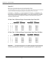
Maximum Current Limited Output:
LC4A
LC4B
LC4C
3.25
Amps RMS continuous.
4.5
Amps RMS peak*
limited.
5.7
Amps RMS continuous.
8.0
Amps peak*
limited.
10.7
Amps RMS continuous.
15.0
Amps peak*
limited.
3.4
LC5A
LC5B
LC5C
14.2
Amps RMS continuous.
20.0
Amps RMS peak*
limited.
3.25
Amps RMS continuous.
4.5
Amps peak*
limited.
7.1
Amps RMS continuous.
10.0
Amps peak*
limited.
10.7
15.0
PWM Operating Frequency:
Approximately 18 KHz.
3.5
Operating Temperature Range:
0 to +50 degrees Celsius. Automatic over
temperature shutdown employed at +50
degrees Celsius on heat sink. Consult
Automotion if a larger range is required.
3.6
LC4D
Operational Voltage Supply Range:
Storage Temperature Range:
-20 to +85 degrees Celsius.
3.7
Operating Humidity Range:
5 to 95% RH non-condensing.
3.8
Output Voltage to Motor:
LC4- Nominally +160 volts chopped DC,
phase-to-phase. This is based upon a supply
voltage of 115 volts AC-RMS, at full-rated
continuous output amps.
LC5- Nominally +320 volts chopped DC,
phase-to-phase. This is based upon a supply
voltage of 230 volts AC-RMS, at full-rated
continuous output amps.
Amps RMS continuous.
Amps peak*
limited.
* Defined as the peak of a six step waveform.
See ``Reversing the Motor, 4 Quadrant
Operation'' for precautionary details.
4
Automotion, Inc. LC4/5 User's Manual
3.9
Product Size:
3.13
User selectable for either 60 or 120 electrical
degrees of signal phase displacement. See section
7.0, ``Motor Requirements.''
Packaged Unit:
Height
9.25
inches (23.5 cm)
Width
5.4
inches (13.7 cm)
Depth
8.5
inches (21.6 cm)
Weight
6.25
lb. max (2.81 Kg)
________________________________
3.14
3.10
10.5
3.5
6.25
3.2
inches (26.7 cm)
inches (8.9 cm)
inches (15.9 cm)
lb. max (1.45 Kg)
3.15
Heat Sink Cooling:
Motor Compatibility:
Any three phase WYE or DELTA wound brushless
DC motor designed to operate with 160 volts DC
power and possessing a minimum winding
inductance of 150 micro Henries or greater and a
minimum winding electrical time constant of 0.5
msec. See Section 7.0, ``Motor Requirements'' for
more information.
External forced air cooling may be necessary
when prolonged high amperage duty cycles are
used and/or high ambient air temperature
exists. The LC4/5 will automatically shutdown
whenever the heat sink temperature reaches
approximately 50 degrees Celsius. To restart
the motor, toggle the Start/Stop input after the
heat sink has cooled.
3.11
Additional Controls:
Start/stop, forward/reverse, dynamic brake,
external current limit trip input, external signal input
for closed loop speed control. An optional current
signal output is available, but must be configured at
the factory. See the Table of Contents for further
information.
Open Frame Unit:
Height
Width
Depth
Weight
Commutation Code:
3.16
Logic Control:
All logic I/O terminals numbered 1 through 14 are
electrically isolated from the AC power. External
logic interfacing should be implemented using TTL
outputs. Simple toggle switches may also be used.
The maximum input voltage should not exceed +24
volts DC. See appendix for suggested wiring
hook-ups.
Speed Control:
Stock model is equipped for both external 4
quadrant speed control or Closed Loop, 2
quadrant internal speed regulation. The
external speed control may be provided by
means of either an analog signal for 0 to +10
volts, or an external PWM source. See the
appropriate sections in this manual for further
details on each of these capabilities. An
optional +/- 10 volt analog signal input card is
available. See Section 19.0, "Optional
Equipment."
3.17
Dynamic Braking Limitations:
Some limitations exist in the use of the dynamic
brake. Dynamic Brake Limitations: Maximum 2%
Duty Cycle. 10 watts continuous/ 650 Watts
intermittent. Please read Section 15.0, ``Dynamic
Braking the Motor,'' if you intend to use this feature.
3 .12 Commutation Control:
3.18
Normally provided by three rotor positional
sensors located within the brushless DC motor.
These sensors may be either of the Hall variety
or optical in nature. See section 7.0, ``Motor
Requirements.''
Full Short Circuit Protection:
The LC4/5 is protected from damage due to a
momentary direct short circuit to ground, a short to
the AC power supply rails, or a phase-to-phase
short. Inadvertent shorts in the motor or motor
phase lines may result in the drive tripping off line
5
Automotion, Inc. LC4/5 User's Manual
and the annunciation of the fault. The fault
may be cleared and the drive restarted
without damage (once the short has been
removed), by resetting the enable/disable
line. Frequent short circuits may eventually
damage the drive.
3.19
If the LC4/5 is subject to frequent power-up
conditions, a different fuse may need to be
specified.
4.0
The following steps should be followed in the
order shown to complete the proper electrical
installation. Always cut and strip only enough
insulation off of connecting wires to mate with
the LC4/5 terminals. Do not leave bare wires
exposed beyond the edge of the terminal block.
This would create a potential hazard to the
operator and the system from short circuits
between adjacent terminals. NEVER MAKE
ELECTRICAL CONNECTIONS OR WIRING
ADJUSTMENTS WITH LIVE POWER APPLIED
TO THE LC4/5 CONTROL. Please refer to
FIGURE 1 for information when performing the
following installation steps.
1500 VAC HiPot Tested:
The LC4/5 is tested at the factory for
dielectric strength between incoming AC
power and user SELV interface circuits. It is
also tested for dielectric strength between
incoming AC power and chassis frame
ground. The HiPot test level used is 1500
VAC between SELV circuits on connector P1
and incoming AC power on connector P2. A
HiPot test level of 1500 VAC is used
between the chassis frame ground and
incoming AC power on connector P2.
3.20
Packaging:
Models with the subscript ``P'' are packaged
in a NEMA 1 type ventilated enclosure. All
others are open frame. DO NOT PLACE
ANY LC4/5 IN CONTACT WITH LIQUIDS,
ELECTRICALLY CONDUCTIVE MATERIALS, OR CORROSIVE CHEMICALS OR
ALLOW FOREIGN MATERIALS TO FALL
INTO THE LC4/5.If the LC4/5 must be used
in an environment which violates these
conditions, contact AUTOMOTION for
special packaging recommendations.
3.21
Quick-Start Set up:
4.1
Step One:
Wire motor phases to proper terminals on the
LC4/5 control. Use the wire sizes recommended
in Section 6.0, ``Power Supply Requirements.''
The three phase wires should be twisted
together with approximately six twists per foot
(0.3 meters).
4.2
Step Two:
Wire the rotor positional sensors into the control.
In a typical installation, there will be 5 wires
serving the sensor assembly. They are: S1, S2,
S3, + low voltage DC power (i.e., Terminal #4,
+12 volt DC), and LOGIC GROUND (i.e.,
Terminal #5).
Fuse Sizes:
When replacing a fuse, always use properly
rated devices. For the LC4A, use only a
LITTELFUSE #314007 or equivalent. For the
LC4B, use only a LITTELFUSE #314010 or
equivalent. For the LC4C, use only a
LITTELFUSE #314020 or equivalent. For the
LC4D, use only a LITTELFUSE #314025 or
equivalent.
Light gauge wire may be used, such as 24 AWG.
When the distance between the motor and the
control exceeds 6 feet (1.8 meters), AUTOMOTION recommends using a shielded cable for the
sensor wires. A single shield covering the entire
bundle should be sufficient with the shield
terminated ONLY at Terminal #5 of the LC4/5
control. The motor end of the shield should be
left open. If unshielded wire is used, twist these
five wires together with approximately six twists
per foot (0.3 meters).
For the LC5A, use only a LITTELFUSE
#314010 or equivalent. For the LC5B, use
only a LITTELFUSE #314015 or equivalent .
For the LC5C, use only a LITTELFUSE
#314020 or equivalent.
6
Automotion, Inc. LC4/5 User's Manual
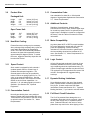
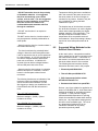
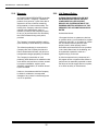
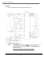
LC4/5 BASIC WIRING DETAILS
FIGURE 1
NOTES!
LOGIC GROUND and chassis ground are NOT common with each other and normally
are kept separate from each other externally. Also, be aware of restrictions
involving the use of the Forward/Reverse at high RPM's. SEE THE MANUAL FOR
ADDITIONAL DETAILS!!
Shown above is a simple open loop speed control installation.
7
Automotion, Inc. LC4/5 User's Manual
4.3
Step Three:
Determine the proper commutation signal
phase shift required for your motor (i.e., 60 or
120 electrical degrees) and place the jumper in
JUMPER GROUP 2 located on the bottom of
the LC4/5 in the proper position as described
below. See FIGURE 4 or FIGURE 5 for
placement details. Units are normally shipped
in the 120 degree mode, unless otherwise
indicated. Reference Section 7.0, ``Motor
Requirements'' for more information.
4.4
4.6
With the external AC 50/60 Hz, feed power
temporarily DISCONNECTED, wire the feeder
block or the power cord into the LC4/5 control at
connector J2. Use the wire sizes recommended
in Section 6.0, ``Power Supply Requirements.''
NEVER MAKE POWER CONNECTIONS TO
THE LC4/5 WITH LIVE AC POWER.
4.7
Decide whether you will be using either open
or closed loop speed control. If open loop is
required, use Terminal #9 as the input for this
0 to + 10 volt analog signal, which is
referenced to LOGIC GROUND (i.e., Terminal
#5). A +10 volt DC signal at Terminal #9 will
run the motor at maximum current limited
RPMs. Please note that for open loop speed
control a simple external potentiometer with a
minimum resistance of 10K ohms may be used
to control your motor RPM's. See section
12.0, "Running the Motor With the LC4/5
Control: CLOSED LOOP" for details.
4.5
Step Seven:
Before operating the LC4/5 control for the first
time, make sure that all logic control inputs are
wired correctly and that the current drain out of
Terminal #4 will be no more than 50 mA.
Whenever AC power is first applied after a
brownout or after a momentary power interruption, the LC4/5 will require a power-up reset. This
is done by toggling the Start/Stop input port (i.e.,
Terminal #6) from OFF to ON. Please note that it
is normal for the ``Power/OT Fault'' and LED to
be lit at power-up or after a power interruption.
Always check the setting of the front panel trim
pots. Improper adjustment can cause needless
delays and trouble. Review Section 5.0, ``Last
Minute Check List'' before operating the LC4/5 for
the first time.
Step Four:
Your LC4/5 is designed to operate in several
different speed control modes. These include:
Open loop, 1, 2, or 4 quadrant speed control
using a 0 to +10 volt analog signal; optional +/10 volt input; internal single quadrant closed
loop speed control with the tach signal
provided by the commutation sensors; internal
single quadrant closed loop speed control with
the tach signal provided by an external
encoder input; external PWM control.
Step Six:
5.0
Last Minute Check List:
(read before operating the LC4/5 for the first
time)
Have you connected your AC power cables
correctly?
______ yes______ no
Are all connectors snapped into place?
Step Five:
______ yes______ no
If you use Forward/Reverse or Dynamic Brake
controls, these ports may be toggled by either
a simple SPDT switch, or by TTL signal
outputs from an external electronic based
control. If external TTL signals are used, the
common return path must be connected to
terminal #5 (LOGIC GROUND).
Have you checked your motor phase output
connections and all other wiring to make certain
there are no shorts?
______ yes______ no
8
Automotion, Inc. LC4/5 User's Manual
Will your power source supply the correct AC
voltage?
MOV protected for very short ``soft'' line
transients above 145 VAC.
______ yes______ no
For the LC5 models,the voltage range must be
between 200 and 245 VAC-RMS or an
automatic shutdown of the control may occur.
Any continuous supplied voltage over 245
VAC-RMS may cause damage to the LC5
control. The AC line inputs for the LC5 are
MOV protected for very short ``soft'' line
transients above 260 VAC.
(Remember to bring the motor speed up
gradually the first time you operate the LC4/5).
Have you adjusted the user accessible trim
pots correctly?
______ yes______ no
Consult AUTOMOTION for limitations.
If you are NOT using input Terminals #10
and/or #11, have you connected them to
Terminal #5 (LOGIC GROUND)?
6.2
Voltage fluctuations on the AC supply line may
adversely affect the maximum RPM level
attainable by your motor and speed stability,
especially when operating in an open loop
mode.
______ yes______ no
Have you read through this manual entirely
including the SAFETY PRECAUTIONS?
______ yes______ no
6.3
If you answer ``NO'' to any of the preceding
questions, make the necessary corrections
before proceeding.
Power Supply Requirements:
6.1
Power Source:
Wire Size:
AUTOMOTION recommends that a minimum
wire size of 16 AWG be used for connecting
the LC4/5 to both the AC power source and to
the three phases of the motor. Use 14 AWG
wire for the motor phase connections and the
AC power connections if the individual wire
lengths exceed 6 feet (1.8 meters).
Please note, upon power up, the drive default
condition for Terminal #6 start/stop is ``Stop''.
Start/stop input must be toggled OFF and ON
to start the motor.
6.0
AC Voltage Fluctuation:
6.4
Cable Requirements
The phase output cable should have a
maximum distributed capacitance of 100 pF/ft
(328 pF/meter) up to a total of 1000 pF.
The power source used with the LC4/5
product family must be a nominal 115 volts for
the LC4 or a nominal 208/220 volts for the LC5
models. This source must be single phase AC
service with a nominal line frequency of 50/60
Hz, +/- 3%, and the amperage capacity for the
supply circuit must be rated at least 10
amperes above the continuous output rating for
your particular LC4/5 model.
Total capacitance being the sum of phase to
phase and phase to ground (shield) capacitance. If cable losses are higher, compensating line inductors may be required. Contact
Automotion for application assistance.
6.5
Fuses:
The LC4/5 product line is internally fused.
Should the fuse blow, always determine why
this occurred before attempting to operate the
LC4/5 again. See Section 3.21 for fuse sizes.
For the LC4 models, the voltage range must be
between 95 and 132 VAC-RMS or an
automatic shutdown of the control may occur.
Any continuous supplied voltage over 132
VAC-RMS may cause damage to the LC4
control. The AC line inputs for the LC4 are
9
Automotion, Inc. LC4/5 User's Manual
6.6
Line Filter:
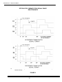
7.3
Phase Shift Selection:
In some noise sensitive or noisy systems, it may be
desirable to place a line filter between the LC4/5 AC
power input terminals and AC power source. Such
devices are commercially available. Ask AUTOMOTION for recommendations.
Before operating, configure the LC4/5 control
to match the phase shift between the signals
supplied by the three rotor positional sensors.
You can use the LC4/5 with either 60 or 120
electrical degree phase shift. See FIGURE 3.
7.0
Motor Requirements:
7.1
Commutation Feedback:
To program the LC4/5, see FIGURE 4 or
FIGURE 5 for an illustration of where to locate
the proper jumper pins on the bottom of the
chassis. All units are shipped from the factory
set for 120 electrical degrees unless
otherwise noted.
The LC4/5 control is designed to operate with a three
phase brushless DC motor. This motor must employ
either three Hall or optical sensors for rotor positional
feedback. These sensors must be capable of
operation off of the +12 VDC supply provided by the
LC4/5. The signal outputs of these sensors may use
either passive or active pull-ups. The LC4/5 DOES
provide internal pull-ups. So, if the sensors used by
your motor do not provide active pull-ups, then
passive external pull-ups of three 10K Ohm, 1/4 Watt
resistors are optional, though recommended. See
FIGURE 2 for details.
For distances less than six feet (1.8 meters), twist the
sensor wires and sensor power wires together with
approximately six twists per foot (0.3 Meter). If the
distance between the motor and control exceeds six
feet (1.8 meters), use shielded wire for the commutation sensor signal lines and the commutation sensor
power lines. DO NOT co-mingle commutation sensor
signal lines with motor phase lines.
7.2
Electrical Characteristics:
The brushless DC motor should be three phase with
either a WYE or DELTA wound stator. The motor
inductance should not be less than 150 micro Henries
phase-to-phase at full amperage. The total number of
poles on the rotor assembly does not affect the
performance of the LC4/5 control except at very high
RPM's.
For the LC4 model, the motor should operate with a
DC voltage power source at a minimum of +200 volts.
For the LC5 model, the motor should operate with a
DC voltage power source at a minimum of +400 volts.
Motors should also pass a HiPot test of 1500VAC or
higher between all phase lines and frame ground, and
also between all phase lines and the commutation
sensors.
10
*
To use the LC4/5 control with 60
electrical degree signal phase shift,
place the Group 2 jumper in
position ``B''.
*
To use the LC4/5 control with 120
electrical degree signal phase shift,
place the Group 2 jumper in
position ``A''.
Please note that the three rotor positional
sensor signals coming into the LC4/5 from
your motor must be square waves. When the
motor is running at a constant velocity, these
signals should exhibit a 50% duty cycle.
The bottom of this page left intentionally
blank.
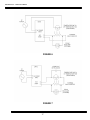
Automotion, Inc. LC4/5 User's Manual
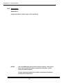
Typical Hall Sensor Interface
(Must be duplicated for each of the three signal inputs).
FIGURE 2
11
Automotion, Inc. LC4/5 User's Manual
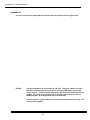
OPTIONS FOR COMMUTATION SIGNAL PHASE
RELATIONSHIPS
NOTE: Each commutation signal has a balanced 50% duty cycle when the motor is running at a
constant velocity.
FIGURE 3
12
Automotion, Inc. LC4/5 User's Manual
FIGURE 4
PACKAGED LC4/5
13
Automotion, Inc. LC4/5 User's Manual
FIGURE 5
OPEN FRAME LC4/5
14
Automotion, Inc. LC4/5 User's Manual
8.0
External Shunt Resistor:
8.2
8.1
Shunt Requirement For Regenerative Braking:
During rapid deceleration of the motor, power
regeneration occurs. This causes kinetic
energy to be returned to the LC4/5 control.
For small inertial loads this may not be a
problem, but for larger loads this returned
energy must be dissipated by the control.
The amount of energy return will depend upon
both the rate of motor deceleration plus the
size of the motor load.
AUTOMOTION recommends that certain
safety precautions be followed in keeping with
good engineering practice when using an
external shunt resistor. In particular the
following considerations are of importance:
·Selection of a properly sized resistor.
·Correct location and mounting for this
external resistor.
·Correct wiring for this resistor to the
Automotion brushless drive.
8.3
The LC4/5 control may be purchased with the
option to use an external shunt resistor. This
is usually a user supplied part. It is absolutely
essential that this shunt resistor be properly
sized and protected. AUTOMOTION will
assist the user in the selection of this part
when requested.
If no external shunt resistor is installed the
user must understand that excess regeneration may cause nuisance trips. While this
occurrence will not damage the control, it will
disrupt the normal operation of the motor.
Consequently, it is necessary for the external
shunt resistor to be properly sized. See
Section 8.3 for advice.
15
Selection of an External Shunt
Resistor Value:
The duty cycle for an external shunt resistor is
application dependent. As such it helps to
estimate just how much kinetic energy is
stored in the motor and its load when
deceleration begins. It is this kinetic energy
which transfers back to the drive whenever a
deceleration cycle begins.
The user is also burdened with the responsibility to make the installation of this external
shunt resistor both fire safe and shock safe.
Should any failure cause this resistor to
overheat or cause its electrical cable to fail,
the user must provide an intrinsically safe
environment for this part so that no fire hazard
can occur. A well designed heat shield is a
user requirement for this part. This shield
must also serve the purpose of preventing
any possibility for a shock or burn hazard.
AUTOMOTION does not recommend that this
resistor be placed in the vicinity of either
combustible or explosive materials and/or
gases.
Shunt Safety Precautions:
AUTOMOTION recommends using the
AUTOMOTION Field Application Bulletin No.
101-0195 for more selection details.
AUTOMOTION DOES NOT recommend the
use of a shunt resistor with less than a 50
Watt rating for any application. Consult
AUTOMOTION if you wish to violate this
guideline.
8.4
Location and Mounting of the
External Shunt Resistor:
The shunt resistor is a heat producing
element powered from high voltage electricity.
Consequently the user must follow several
common sense safety guidelines to avoid
possible problems later. The following is a list
of suggested methods for mounting the
external shunt resistor:
Automotion, Inc. LC4/5 User's Manual
· DO NOT mount the shunt in the proximity
of flammable materials. It is suggested
that it be mounted only upon a metal
surface, such as steel. It is also suggested
that if it is to be installed in an enclosure,
then this enclosure be made out of
nonflammable metal materials with flow
through air ventilation.
Temperature limiting devices are available to
aid in the removal of the power source from
the shunt resistor in the event it begins to
overheat for any reason. However, they are
not a substitute for making the basic
installation fire proof.
The simplest way to limit the heat concentration at the shunt resistor is to use the highest
ohmic value resistor(s)possible plus higher
wattage capacity in every application. This
will help to keep shunt resistor surface
temperature as low as possible under all
circumstances. Worst case testing is always
required to insure safe performance at all
times.
· DO NOT use the shunt in an explosive
atmosphere.
·DO NOT use the shunt in a location where it
may be exposed to humidity condensation or
other liquids.
· Always locate the shunt in a location where it
will remain clean and dry.
· The shunt is activated by potentially lethal
voltages. Mount the shunt someplace where
it will not expose the user or service personnel
to a shock hazard. A 115 VAC sourced drive
can deliver voltages between 200 and 250
peak volts to the shunt. A 208/230 VAC
sourced drive can deliver voltages between
400 and 450 peak volts to the shunt.
· Always locate the shunt resistor in a location
where it has space for ventilation. DO NOT
locate in a closed space without free air
movement.
The following formulas are an indication of the
maximum continuous wattage developed
across the shunt when whenever it is ON.
We suggest you design your installation to be
fire and shock safe with this information in
mind.
For a 115 VAC sourced drive:
Maximum wattage = (34150) / (Shunt
resistance in Ohms)
For a 208/230 VAC sourced drive:
Maximum wattage = (132500) / (Shunt
resistance in Ohms)
16
8.5
Suggested Wiring Methods for the
External Shunt Resistor :
At the user's option, a temperature sensitive
fuse or switch can be used in conjunction with
the external shunt resistor. The function of
this device is to limit the temperature rise of
the shunt resistor should it ever overheat.
The following devices have been tried by
Automotion and show merit in this purpose.
1. Elmwood part #JD090-V231.
2. Therm-O-Disc part #G5A01077C.
3. RCD Components fusible resistor
#TF04D/.25 Ohm/±5% Tol.
4. Bussman heat limiter fuse part #TGC.
Devices 1 and 2 are suitable for application as
shown in FIGURE 6 ONLY! All of these listed
devices are suitable for application as shown
in FIGURE 7. Each part has a slightly
different threshold temperature for opening.
Check the manufacturers data sheet carefully
before use. Any temperature sensing device
should be a non-resettable type. The use of
any temperature limiting device is not
intended to substitute for any safety
precautions previously stated.
Automotion, Inc. LC4/5 User's Manual
FIGURE 6
FIGURE 7
17
Automotion, Inc. LC4/5 User's Manual
The optional neon lamp is intended to show
the user just how heavy a duty cycle is
applied to the shunt resistor. It will blink every
time the shunt resistor is toggled. If it blinks
with a very short duty cycle under worst case
decel conditions, the chances are that a
higher ohmic resistor value could be used. If
it DOES NOT blink at all an external shunt
resistor may not be needed.
If the user decides to use a temperature
sensitive fuse or switch, it is very important
that this device be located in close proximity
to the shunt resistor. It is obvious that if the
surface temperature of the shunt resistor
becomes excessively hot the components
listed on the previous page must respond
effectively. Generally the temperature
sensitive device should be mounted in contact
with the surface of the shunt resistor or very
close to it.
Automotion favors the use of the installation
shown in FIGURE 6 whenever possible. This
is because it requires fewer components. If
the installation in FIGURE 7 is used, the 1 µf
capacitor should be located away from the
path of heat if the shunt resistor should
overheat.
The capacitor shown in FIGURE 7 is made by
General Electric under their part #40L6101. It
may be possible to find an equivalent
substitute. It is non-polarized and rated for
600 Volt DC service. If the installation shown
in FIGURE 7 is used then this capacitor is
required. Any installation without it is likely to
render the temperature fuse or temperature
switch as ineffective.
Whichever method is chosen to locate the
external shunt resistor, it should be wired to
the Automotion drive using at least 16 AWG
wire rated for 600 VAC service. We
recommend that the wire have a Teflon jacket
with a minimum 105° C temperature rating.
Wiring guidelines are given in Section 8.1,
"Shunt Requirement For Regenerative
Braking". It is important that the wire to the
shunt resistor be dressed using good
installation practice to prevent any short
circuits from happening. Short circuits will
damage the Automotion drive.
18
The final method of installation should be
tested to confirm that it functions correctly and
safely. Also apply heat to the temperature
sensing device chosen to confirm that it works
consistently in your operating environment.
Multiple tests are recommended.
Any questions regarding the external shunt
resistor should be directed to AUTOMOTION.
These recommendations are intended to
provide some help in your installation of an
external shunt resistor. They are not a
substitute for using good judgment and
following recognized standards in your
industry for making your installation safe and
reliable under all possible conditions.
The bottom of this page is intentionally blank.
Automotion, Inc. LC4/5 User's Manual
9.0
Input/Output Terminal Identification:
Terminal
Number
Function
Description
9
1
COMMUTATION SIGNAL S1, INPUT
PORT. Digital signal required from
motor. A 10K ohm pull-up resistor
is provided internally.
2
COMMUTATION SIGNAL S2, INPUT
PORT. Digital signal required from
motor. A 10K ohm pull-up resistor is
provided internally.
3
COMMUTATION SIGNAL S3, INPUT
PORT. Digital signal required from
motor. A 10K ohm pull-up resistor
is provided internally.
4
+12 VOLT DC REGULATEDOUTPUT
PORT. 25 mA maximum load. This
may be the power source for the
commutation sensors in motor and
some external logic.
5
LOGIC GROUND. All external logic
should be referenced here. This port
is isolated from chassis frame ground
and from the AC power lines.
6
START/STOP CONTROL INPUT
PORT. Approximately 4.7K ohm input
Z. This port is TTL compatible. The
maximum applied voltage here must
not exceed +24 VDC. 0 volts stops
the control. The default condition is
STOP.
7
8
Terminal
Number
FORWARD/REVERSE DIRECTION
CONTROL, INPUT PORT. This port is
TTL compatible. The maximum
applied voltage here must not exceed
+24 VDC. O volts enables ``forward''
motor rotation. Default condition is
FORWARD.
DYNAMIC BRAKE CONTROL,
INPUT PORT. This port is TTL
compatible. 0 volts turns off the
brake. The default condition is brake
``OFF''.
19
Function
Description
OPEN LOOP SPEED CONTROL
INPUT PORT. Requires a 0 to +10
volt signal to set the open loop motor
speed. +10 volts produces maximum
motor RPM's and 100% PWM
amplifier output. 0 volts produces zero
motor speed and 0% PWM amplifier
output. The input Z is approximately 22K
ohm. The default condition is zero speed.
(+/- volt input optional.)
10 DUAL SPEED SELECT CONTROL,
INPUT PORT. A TTL compatible port
for selecting one of two Closed Loop
speed settings. This uses the internal
single quadrant Closed Loop speed
control. Both speed settings are
controlled through built-in pots. The
default condition selects Velocity Setpoint
#1.
11 EXTERNAL CLOSED LOOP SPEED
CONTROL, INPUT PORT. This port
allows for an external signal source to
control the internal single quadrant Closed
Loop speed. The input Z is approximately
10K ohm.
12 EXTERNAL ENCODER/ EXTERNAL
PWM INPUT PORT. This port is TTL
compatible. The maximum applied
voltage here must not exceed +24 VDC.
See Sections 12, 13, and Appendix A &
B for configuration details.
13 CURRENT SIGNAL OUTPUT PORT.
(Optional). Approximately +.05
volts/Ampere. See Section 19.1 for
details.
14 EXT. CURRENT LIMIT TRIP, INPUT
PORT. Whenever a digital signal is
applied here of +12 volts in amplitude, the
LC4/5 stops sourcing current to the motor.
Input Z is approximately 22K ohms. See
Section 17.0 for details.
15 CHASSIS FRAME GROUND (i.e., heat
sink)
Automotion, Inc. LC4/5 User's Manual
16 AC NEUTRAL POWER
INPUT PORT.
LC4- 115 VOLTS AC,50/60 Hz.
LC5- 208/220 VOLTS AC, 50/60 Hz,
(Not Fused.).
cally shut down. If the surface temperature of
the mounting base of heat sink is around or
above 50 degrees Celsius, additional forced
air cooling will be required.
Do not place the LC4/5 in an environment
subject to high vibrational stress. If this is
necessary, contact AUTOMOTION.
17 AC HOT POWER INPUT
PORT.
LC4- 115 VOLTS AC, 50/60Hz.
LC5- 208/220 VOLTS AC, 50/60 Hz,
(Fused).
This product contains capacitors which store a
high voltage electric charge for several
minutes after all outside power is removed.
Beware that at least 12 minutes must pass
after all external power is disconnected before
this product may be physically handled.
18 MOTOR PHASE #1 OUTPUT.
19 MOTOR PHASE #2 OUTPUT.
20 MOTOR PHASE #3 OUTPUT.
10.0
Installation: Mechanical:
10.1
General Information for all Installations:
10.2
Never mount this product in the vicinity of
combustible materials. Never use this product
in an atmosphere of potentially explosive or
highly combustible gas and/or dust. Direct
contact with liquids, corrosive chemicals, or
corrosive gases must be avoided. The LC4/5
10.3
must be used in environments which have a
supply of clean and dry air. High humidity is to
be avoided where there is a risk of condensation.
The LC4/5 must always be located inside an
enclosure which is both intrinsically fire safe
and electric shock safe. This may necessitate
the need for safety interlocks on the outside
enclosure to disconnect all power whenever
service is performed.
Mount the LC4/5 vertically on a clean and flat
surface. This will provide natural convection air
cooling. The need for forced air cooling may
be required in environments with high ambient
air temperatures and/or heavy duty cycles.
Whenever the heat sink temperature reaches
approximately 50 degrees Celsius (122
degrees Fahrenheit), the LC4/5 will automati-
20
Packaged Models:
The LC4/5 model "P" unit is a packaged
device designed to conform to NEMA type 1
standards. The control is designed to mount
vertically so that convection air flows naturally
through the heat sink fins. If the control is
mounted in any other manner, forced air
cooling may be required. Notches in the side
brackets are provided for mounting the unit.
Never drill holes into or mount brackets upon
the case.
Open Frame Models:
The LC4/5 model "O" unit is an open frame
device. It has no cover wrapped around it
which is designed to provide complete
mechanical or electrical protection. This
requires the user to provide adequate
protection as needed. In particular the user
must mount and use the LC4/5 open frame
control inside of a protective enclosure which
is both fire safe and electric shock safe.
The open frame device is designed to be
mounted upon a cold plate surface. This
means it must be placed upon a surface which
has sufficient thermal mass to draw the heat
away from the rear mounting surface of the
control.
Automotion, Inc. LC4/5 User's Manual
11.0
Running the Motor With the LC4/5
Control - OPEN LOOP:
11.1
Set up:
The Appendix shows several examples of how
an external speed control may be provided in
the open loop mode.
To operate the LC4/5 control in an open loop
mode means that there is not any built-in
means of speed regulation. Rather, the speed
will be governed based upon the analog
signal supplied on Terminal #9. Other factors
influencing speed stability in an open loop mode
are the load applied to the motor, the AC line
voltage stability, and the maximum current
delivery of the LC4/5 model being used.
To set up the control for open loop operation,
examine FIGURE 4 or FIGURE 5. Locate and
adjust the Velocity Set #1 and the Tach Gain
pots fully counter-clockwise. Locate and adjust
the Velocity Set #2 pot fully clockwise. These
three pots are approximately 17 turn devices
and to adjust them will usually produce a
noticeable "click" when they are at the fully
CCW or CW extremes. Also decide how much,
if any, "Soft Start" time is needed, and how
much current limited output is required. Refer
to Section 17.0, "Setting the Maximum Current
Limited Output" and Section 16.0, "Using Soft
Start."
11.2
Speed Control
To control the speed a 0 to +10 volt signal must
be applied to Terminal #9. This variable analog 12.0
voltage should be referenced to Terminal #5
(LOGIC GROUND). The amplitude of the
analog voltage applied to Terminal #9 linearly
12.1
modulates the duty cycle of the PWM controlled
output voltage to the motor windings.
At 100% duty cycle modulation the motor will
rotate at maximum speed. If the motor is
unloaded, the speed will only be limited by the
peak-to-peak voltage applied to the motor,
which is a nominal +160 volts for the LC4 and
+320 volts for the LC5. If the load upon the
motor increases enough to cause excessive
current to be drawn, the PWM duty cycle will
automatically be reduced to limit the peak
current level, causing the speed to fall off.
21
Before running the motor, pre-select the
commutation phase code, set the motor drive
direction by using Terminal #7, and disable the
Dynamic Brake by applying 0 volts to Terminal
#8. Limitations apply for rapid direction
changes at rotational speeds above 1000 RPM.
See Section 14.0, "Reversing the Motor, 4
Quadrant Operation."
Remember, upon initial power up or after a
momentary power loss, the LC4/5 default
condition is stop. The start/stop input must be
toggled once to start the motor.
To start the control, Terminal #6 must be
activated by a +5 volt TTL signal. Now the
analog voltage may be increased on Terminal
#9. If the motor is wired correctly, it should
begin to turn slowly, but smoothly, as the
analog voltage increases at Terminal #9. Also
wire Terminals #10 and #11 to Terminal #5
(LOGIC GROUND) if the internal closed loop
speed control is not to be used. When running
in the open loop mode, the signal applied to
Terminal #9 proportionally controls the amount
of modulation applied to the motor. However,
the speed of the motor in the open loop mode
will NOT necessarily vary in direct proportion to
the voltage applied to Terminal #9.
Running the Motor With the LC4/5
Control - CLOSED LOOP:
Set up:
To operate in a closed loop mode the speed is
regulated through a means of feedback control.
This feedback system will automatically try to
compensate for fluctuations in either the motor
load or the supply voltage, which would
otherwise change the speed.
The built-in closed loop speed control system
on the LC4/5 is 2 quadrant only. If the motor
speed should overshoot the setpoint or if there
is an overriding load, the control will not
produce a negative torque on the motor to slow
it down. Rather, the LC4/5 will simply stop
Automotion, Inc. LC4/5 User's Manual
sourcing power to the motor until the speed
drops. More elaborate 4 quadrant performance may be achieved with the Forward/
Reverse and/or Dynamic Brake functions,
however, certain limitations apply. AUTOMOTION does not recommend toggling the
Forward/Reverse line while under closed loop
control unless the Current Limit pot setting is
set midway. (i.e., 8 turns off fully CCW). The
built-in closed loop speed control system on
the LC4/5 is designed for 2 quadrant velocity
loop control only.
speed. The maximum allowable voltage input
on Terminal #10 is +24 volts DC and the
minimum voltage input is -0.3 volts DC.
The maximum speed level using pot #2 can
never exceed the speed setting for pot #1.
These two pots can be used for dual RPM
level shifting while under closed loop speed
control. Just remember to select the desired
pot using Terminal #10 as described above.
12.3
The built-in closed loop speed control system
on the LC4/5 allows two options for creating a
tachometer signal necessary for speed
regulation. They are:
1.
2.
1. Internal speed pots
2. Externally supplied voltage reference
12.2
To supply an external reference voltage to set
the closed loop speed, adjust both pot #1 and
pot #2 to their fully CCW positions. These
pots are 17 turn types. Use Terminal #11 as
the input port for this externally supplied
signal. The signal amplitude applied to
Terminal #11 should range from 0 to +10 volts
for full range control. The maximum voltage
should not exceed +12 volts or be less than
-0.3 volts. When Terminal #11 is not in use it
should be left disconnected or strapped to
Terminal #5 (LOGIC GROUND). After the
Tach Gain Pot is adjusted, the voltage span to
attain full speed may become very narrow.
External scaling may be effected through the
use of a series resistor with terminal #11.
Hall Signal feedback
External encoder feedback
The Hall signal feedback is provided by the
motor. It is not as effective as a high
resolution encoder at low speeds or where
tight speed regulation is required (< +/- 1%).
In general, the Hall signal approach is suitable
for speeds above 350 RPM.
To select the Hall signal feedback mode,
place the jumper in Group 1 in position "A".
Place it in position "B" to select the external
encoder feedback mode. Speed stability with
either approach is influenced by the setting of
the Tach Gain pot, the Slew pot, the load, and
the total dynamic speed range of the motor.
To control the closed loop speed, the LC4/5
allows two options. They are:
Use of Internal Speed Pots:
To use the internal speed pots, note the front
panel layout in FIGURE 4 or FIGURE 5.
There are two on-board pots used for setting
the closed loop speed. They are designated
"Vel. Set #1" and "Vel. Set #2." With a TTL
logic level "0" input on Terminal #10, pot #1 is
automatically selected as the primary speed
control pot. "Vel. Set #2" is your secondary
speed control pot selected by TTL logic level
"1" input on Terminal #10. Both pots are 17
turn devices with full CW producing maximum
22
Use of an External Voltage
Reference:
12.4
Tach Gain and Slew Adjustments:
When using closed loop control, the proper
adjustment of the tach gain pot will impact
the performance of the motor under changing
load conditions. Automotion recommends
that, initially, the tach gain pot, which is a 17
turn device, be set approximately halfway.
This establishes a moderate tach gain. Higher
or lower gain may be needed later, depending
upon the desired system response and
stiffness. In general, a higher tach gain setting
will provide for a lower speed drop as the
motor load increases.
If the motor vibrates, or the speed is erratic,
the LC4/5 could be in a current limit mode or
there could be too much system gain, or poor
loop compensation. One possible solution is
to adjust the slew pot to reduce the loop
response {i.e.,CCW}. If the LC4/5 is in a
Automotion, Inc. LC4/5 User's Manual
current limit mode the "Current Limit" red LED
will glow.
14.0
The slew pot helps produce a lag in overall
loop response when operating under closed
loop conditions. This pot should be left in the
fully CW position for the fastest loop
response. Before operating the LC4/5 under
internal closed loop control disconnect any
input connection to Terminal #9. It could
prevent proper performance of the internal
closed loop system. Please refer to
Appendices for additional information and
suggested wiring connections.
The LC4/5 control permits the reversal of the
motor while in motion. However, some
discretion is required when under closed loop
or operating above the 1000 RPM level.
Please refer to Appendix for additional
information and suggested wiring connections.
A 4 quadrant drive means the motor and
control can produce a negative torque which
opposes the direction of shaft rotation. This
negative torque is limited by the maximum
output current and the torque constant of the
motor. This operation is different than
dynamic braking since the effects of negative
torque by dynamic braking decrease with
lower shaft speeds.
13.0 External PWM Speed Control:
An external digital PWM signal can be used to
control the output modulation to the motor. If
one is used, AUTOMOTION recommends that
the base frequency be no higher than 20 KHz.
To set-up external PWM, place the LC4/5 in
the Stop mode. Next, strap Terminal #9 to
Terminal #4. Examine FIGURE 4 or FIGURE
5 to locate and place the Group 1 jumper in
position "C". The external PWM signal source
must be fed into the LC4/5 via Terminal #12.
This signal source should be TTL compatible.
The logic inside the LC4/5 is positive true. A
logic high level for the PWM signal translates
into an ON condition in the output amplifier.
The external PWM source will have complete
speed control over the motor.
except when the output is in a current limited
state. Whenever the motor goes into current
limit the output modulation and override the
external PWM source.
If the motor goes into a current limit mode, the
Current Limit LED on the front panel will glow.
The brighter the glow, the higher the peak
current draw. Precise speed may be difficult
to maintain when operating in a current limit
mode.
23
Reversing the Motor, 4 Quadrant
Operation:
Under closed loop control, if the motor is to be
subject to direction reversals AUTOMOTION
requires that the Current Limit setpoint be
reduced. Looking at the front panel find the
Current Limit pot. This pot should be adjusted
for a halfway position (approximately 8 turns
off the fully CCW position).
15.0
Dynamic Braking the Motor:
When it is desirable to dynamically brake the
motor, Terminal #8 should be toggled to a
TTL logic ``1'' level. The maximum signal
amplitude allowed here is +24 volts.
To release the dynamic brake pull Terminal #8
down to LOGIC GROUND potential as found
on Terminal #5 or apply a TTL logic ``0'' level
signal. Do not take the voltage on Terminal #8
below LOGIC GROUND potential, which is 0
volts.
In order for the dynamic brake to be fully
effective, the voltage on Terminal #9 during
the braking cycle must be +10 volts DC. Any
voltage less than +10 volts DC will begin to
diminish the effectiveness of the dynamic
brake. This has the benefit in allowing the
deceleration rate to be controlled. However,
the effect of the brake drops off rapidly with
Automotion, Inc. LC4/5 User's Manual
16.0
voltage levels much below +9 volts DC on
Terminal #9 during a dynamic brake cycle.
LC4/5, the Start/Stop input must be toggled
from OFF to ON.
The standard dynamic brake feature can
absorb energy at a rate of 10 Watts
continuously and 650 Watts intermittently.
This translates into a maximum duty cycle
rate 2% ON and 98% OFF, or 3 Seconds ON
and 150 Seconds (or longer) OFF. If higher
rates are required, consult AUTOMOTION.
You can remotely control the trip level of
current limit by feeding a digital pulse signal,
between 2 and 10 uSec. in duration, into
Terminal #14. This signal must be +12 volts in
amplitude as referenced to Terminal #5
(LOGIC GROUND). When a +12 volt digital
pulse with a fast leading edge is applied to
Terminal #14, the LC4/5 will turn off output
amperage to the motor until the next cycle
begins on the internal 18 KHz PWM oscillator.
Using Soft Start:
The LC4/5 control has a built-in Soft Start
feature. This permits the acceleration rate for
the motor to be controlled. To locate the Soft
Start pot, refer to FIGURE 4 or FIGURE 5.
When adjusted to the maximum setting
clockwise, the motor will accelerate at the
slowest rate. Acceleration at this rate may
take 60 seconds or more to reach setpoint
speed. When the Soft Start pot is set for the
minimum setting (i.e., maximum acceleration)
it must be in the fully counter-clockwise
position. This pot is a 12 turn device.
The Soft Start feature is useful in accelerating
delicate loads up to running speeds. The Soft
Start feature is only in effect after the
Start/Stop input signal on Terminal #6 is
toggled. Once the Soft Start cycle times out,
it cannot be repeated until the Start/Stop input
is again toggled OFF and back ON.
17.0
Setting the Maximum Current
Limited Output:
This is useful when used in conjunction with
the Current Signal Output Option which can
be ordered with the LC4/5. The combination
of this option and a simple comparator circuit
will allow the user to remotely control the
current limit setpoint.
18.0
In Case of Trouble:
Should your motor and LC4/5 control not
perform properly after following the installation
and operation procedures, read through this
list of symptoms.
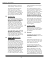
18.1
Symptom 1:
Running the motor in the open loop mode
nothing happens (i.e., the rotor does not move
at all once power is applied).
* SOLUTION *
The Current Limit pot located on the front
panel of the LC4/5 (See FIGURE 1) is used to
set the maximum current limited delivery from
the LC4/5 control. The peak current output will
reach a maximum level after approximately 17
full CW turns on the Current Limit pot. The
relationship between the actual current limit
and the pot setting is linear. When the LC4/5
is in a current limit mode, the ``Current Limit''
red LED will glow. Should the rotor of the
motor ever become firmly locked during a run
condition, the LC4/5 will automatically shut
down after a few seconds and the ``Current
Limit'' red LED will glow brightly. To restart the
24
Check that only the Green LEDs are lit. If all
LEDs are off, check that the AC power supply
connections are correct and that 115 volt AC
power is applied. Check the fuse.
If the fuse is blown check each output
connection for shorts or otherwise improper
wiring. If the fuse blows a second time contact
AUTOMOTION immediately.
Should any red LEDs be lit, see the LED
diagnostics chart for advice. The motor will
not run in the open loop speed control mode
without a voltage above LOGIC GROUND up
to +10 volts being applied to Terminal #9. Try
toggling the Start/Stop input port, Terminal #6,
Automotion, Inc. LC4/5 User's Manual
first to 0 volts DC and then to +5 volts DC.
Remember that a 0 volt DC signal is required
at the Dynamic Brake input port, Terminal #8.
Both closed loop speed control pots, Vel. Set
#1 and #2, must be set FULLY CCW and the
Tach Gain pot must be set FULLY CCW in
order to attain full open loop rotor speed. Note
that all external logic control signals applied to
the LC4/5 must be referenced to Terminal #5
(LOGIC GROUND).
commutation efficiency.
When the commutation is properly ``NEUTRALIZED,'' the motor will run at the same
RPM in both directions while unloaded using a
constant speed control signal into Terminal
#9.
Has jumper Group 2 (See FIGURE 4 or
FIGURE 5) been properly programmed to
select either 120 or 60 degree phase shift for
the commutation signals?
Are the three motor phase output connections
connected?
Are all of the LC4/5 wiring connections placed
into their respective terminals securely?
18.3
The rotor jerks erratically back and forth, or
the motor vibrates while in motion.
Are the front panel connectors snapped into
place securely?
* SOLUTION *
Check your three rotor positional sensors for
proper electrical connections and check that
you have properly selected your sensor signal
phase angle. Are the three rotor position
sensor signals, designated S1, S2 and S3, of
proper amplitude? (i.e., +12 volts DC for a ``1''
state and 0 volts for a ``0'' state. See FIGURE
3). The Appendix contains suggested wiring
connections for several popular brushless
motor manufacturers.
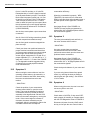
18.2
Symptom 3:
Are motor output phase connections
connected and in the correct order? Also
perform the same check upon the three rotor
positional sensor connections.
Has jumper Group 2 (See FIGURE 4 or
FIGURE 5) been properly programmed to
select either 120 or 60 degree phase shift for
the commutation signals?
Check the dynamic balance of your motor and
load.
Symptom 2:
When running the motor without a load, the
operating current seems to be excessive, or
the motor vibrates at low RPM. Alternatively,
the motor must be hand-turned to start
rotation.
If you are using internal closed loop speed
control, try reducing the slew pot setting or
reducing the tach gain setting. See Section
12.4 for details.
18.4
* SOLUTION *
Check the position of your commutation
sensors located within or upon the motor
frame. They must be adjusted for optimum
commutation efficiency. Rotate the sensor
assembly a few degrees both CW and CCW
relative to the stator and again try running the
motor. If the current begins to increase or
decrease, the sensor assembly may be
misaligned. Adjust it accordingly to reduce the
unloaded current drawn and improve
25
Symptom 4:
When running the motor, the rotor hums and
moves very little or not at all.
* SOLUTION *
Check status of all LEDs. If they are all OFF,
read symptom #1 carefully or compare status
with the LED Diagnostics Chart in FIGURE 8.
Disconnect all power from the LC4/5 control
and try to free spin the rotor. Does it bind or
Automotion, Inc. LC4/5 User's Manual
LED Diagnostics Chart
For use in conjunction with Figures 4 and 5.
FIGURE 8
NOTE! See the manual for additional details on each individual condition listed in the chart
above.
26
Automotion, Inc. LC4/5 User's Manual
feel excessively stiff? Investigate for possible
motor bearing misalignment or damage.
Check for shorts in the motor phase lines either phase-to-phase or phase-to-ground.
Is the load which is coupled to the rotor shaft
excessive or binding? Check this carefully.
Try running the motor without the load.
Check your 115 VAC ( for a LC4) or 220 VAC
(for a LC5) supply line for severe line
transients or surges with high peak voltages.
It may be necessary to add an external line
filter. Contact AUTOMOTION for suggestions.
Are there any commutation dead spots?
Monitor the signals from the three rotor
positional sensors, designated S1, S2 and S3
one at a time. Use a voltmeter with power
applied to the drive then slowly rotate the
motor shaft by hand through one complete
revolution. Each transition to a ``1'' state
should produce a +12 volt DC signal into the
appropriate LC4/5 input terminal. Each
transition to a ``0'' state should produce a
near 0 volt signal into the appropriate LC4/5
input terminal. Contact AUTOMOTION for
details. Check solution for Symptom 3.
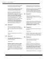
18.5
Symptom 7:
When dynamically braking the motor, the
``Power/OT Fault'' red LED comes on and the
motor shuts down.
* SOLUTION *
The duty cycle of the dynamic brake may be
excessive. Reduce the frequency of braking if
possible. Otherwise an auxiliary braking
resistor may need to be installed. Contact
AUTOMOTION for assistance.
Symptom 5:
When the motor begins to accelerate the
control shuts down and the motor coasts to a
stop. The ``Power/OT Fault'' red LED comes
on.
18.6
18.7
18.8
Symptom 8:
The dynamic brake has little effect in slowing
the motor.
* SOLUTION *
* SOLUTION *
The AC line voltage may be low. Check this
carefully.
When the dynamic brake is applied, check the
voltage at Terminal #9. This voltage needs to
be +10 volts DC. See Section 15.0 for details.
Symptom 6:
When attempting to run the motor, the
``Power/OT Fault'' red LED comes on and/or
the motor shuts down.
18.9
Symptom 9:
When running motor under closed loop
control, the speed is not stable.
* SOLUTION *
* SOLUTION *
Check your supply line voltage. If it is below
95 volts AC for a LC4; or if it is below 190
VAC for a LC5; the control will shutdown
automatically. Check the temperature of the
LC4/5 chassis. If it is near or above 50
degrees Celsius (122 degrees Fahrenheit) the
control is too hot and will shutdown automatically.
Check the ``Current Limit'' red LED. If it is
glowing then the motor is drawing enough
current while spinning to force the drive into a
current limit mode. This can adversely affect
speed stability because the motor is being
starved for sufficient current to operate. Set
the Current Limit pot at its maximum CW limit.
Check the load upon the motor. Is it excessive
27
Automotion, Inc. LC4/5 User's Manual
or binding? Does the motor shaft spin freely
when the external load is removed? The load
upon the motor shaft may be excessive and
more power may be required than either the
LC4/5 or the motor can deliver. Check the
solutions for Symptoms 2 and 4.
If the above steps fail to correct the problem,
contact AUTOMOTION. DO NOT attempt to
service the LC4/5 control. To do so will
immediately void the warranty and expose the
user to hazardous voltages.
19.0
Optional Equipment:
19.1
Current Signal Output Option:
VEL. SET #1
VEL SET #2
TACH GAIN
SLEW
The optional current signal output feature
must be configured at the time of purchase
and cannot be added in the field. This option
produces an analog signal output which is
proportional to the delivered amperage
through the motor.
The calibration factor for this analog signal is
approximately +.05 volts per Amp. There is a
built-in offset voltage of approximately +6
volts DC. The amperage signal will ride on top
of this offset voltage. Some low pass filtration
may be needed for this signal because the
drive's 18 KHz chopping rate will cause this
signal to have some high frequency ringing
upon it. The appropriate time constant for this
filter will vary depending upon the application.
AUTOMOTION will be pleased to provide
application support if needed.
The maximum load impedance on Terminal
#13 should be no less than 10K ohm.
Refer to Section 9.0, ``Input/Output Terminal
Identification,'' and FIGURE 9 for additional
information.
19.2
Terminal #9 on the LC4/5. Please note that
Terminal #9 is the open loop input port for the
LC4/5. The speed may then be throttled and
the direction of rotation controlled by using a
singular bipolar analog signal into Terminal #9
when using this option. However, the LC4/5
will NOT regulate speed under varying load
conditions when using this option. The user
must provide for the closed loop speed
regulation in their external system hardware.
When the LC4/5 is equipped with this option
the following pots are disabled permanently:
+/- 10 Volt Analog Control Option:
The LC4/5 may be purchased with an option
to permit the user to use an external +/- 10
Volt signal to control the motor velocity. If
your drive is equipped with this option, your
+/- 10 Volt control signal must be coupled into
28
This means that the LC4/5's on board 2
quadrant speed control system is nonfunctional.
To use the LC4/5 when equipped with this
option, the absolute amplitude of the applied
signal on Terminal #9 controls in direct
proportion the amount of applied voltage
modulation to the motor. This means 0 Volts
translates into approximately 0% PWM output
and +/-10 Volts translates into approximately
100% PWM output to the motor.
The level of applied modulation may or may
not vary the speed of the motor in a linear
fashion. Linearity is a function of a number of
factors, such as motor design and motor load.
This is why if precise speed control is needed,
an external speed regulator system is
required.
The input impedance looking into Terminal #9
on the LC4/5 equipped with this option is
approximately 5K Ohm. The polarity of the
applied signal into Terminal #9 controls the
direction of shaft rotation. The relative
direction of shaft rotation for positive or
negative signal polarity may be programmed
into the LC4/5 by the user if a jumper wire is
connected between Terminal #7 and either
Terminal #4 or Terminal #5. Do NOT ever
short Terminals #4 and #5 together.
Automotion, Inc. LC4/5 User's Manual
19.3
External Variable DC Bus Input
Option:
The LC4/5 product may be purchased with an
option to permit the user to supply a variable
DC rail input to the drive. This substitutes for
the fixed voltage AC power source normally
used as a power supply for the motor rail.
This option must be configured at the factory.
It allows the user to supply an external rail of
either 15 to 200 volts DC for a LC4 model, or
15 to 400 volts DC for a LC5 model. This is
done through a separate 2 pin power
connector that is installed when this option is
specified. See APPENDIX for details.
The bottom of this page left intentionally
blank.
29
Automotion, Inc. LC4/5 User's Manual
Use of the optional current signal output feature.
FIGURE 9
Suggested method for current loop feedback.
30
Automotion, Inc. LC4/5 User's Manual
20.0
Custom Features Section:
If your unit included any non-standard, custom features; they would be listed here.
31
Automotion, Inc. LC4/5 User's Manual
21.0
Warranty:
22.0
AUTOMOTION INCORPORATED hereinafter
referred to as the ``Company,'' warrants its
products for a period of 2 years from date of
shipment to be free of defects caused by
faulty material or inferior workmanship. The
liability of the Company under this warranty
extends to the replacement, repair, or
issuance of credit, at the Company's option,
for any of its products which are returned by
the initial Purchaser during such period,
provided:
The Company is promptly notified in writing
upon discovery of such defects by Purchaser.
The defective product(s) is returned to the
Company after the Company has issued a
Return Authorization Number, with all return
transportation charges prepaid by Purchaser.
The Company's examination of such
product(s) shall disclose to its satisfaction that
such defects exist and have not been caused
by improper installation, neglect, repair,
alteration, misapplication, or accident caused
by the Purchaser.
Under no circumstances shall the Company
be liable for collateral or consequential
damages of any nature incurred through the
use of our products.
32
Life Support Policy:
AUTOMOTION'S PRODUCTS ARE NOT
AUTHORIZED FOR USE AS CRITICAL
COMPONENTS IN LIFE SUPPORT
DEVICES OR SYSTEMS WITHOUT THE
EXPRESS WRITTEN APPROVAL OF THE
PRESIDENT OF AUTOMOTION INCORPORATED.
As described herein:
Life support devices or systems are devices
or systems which, (a) are intended for surgical
implant into the body, or (b) support or sustain
life, and whose failure to perform, when
properly used in when properly used in
accordance with instructions for use provided
in the User's Manual and in the labeling, can
be reasonable expected to result in a
significant injury to the user.
A critical component is any component of a
life support device or system whose failure to
perform can be reasonably expected to cause
the failure of the life support device or system,
or to affect its safety or effectiveness.
Automotion, Inc. LC4/5 User's Manual
23.0
Appendices:
Appendix A:
Suggested method for external logic control interfacing.
NOTES:
Use of the PWM signal input for speed control is optional. If this input is
to be used Terminal #9 should be connected to Terminal #4. See the
manual for additional details.
All logic input/output signals on the LC4/5 are electrically isolated from
the motor drive output power.
33
Automotion, Inc. LC4/5 User's Manual
Appendix B:
Use of an external input signal with an external closed loop speed reference signal input.
NOTES:
The input impedance of Terminal #11 is 10K ohm. Therefore, both the low pass
filter time constant required to smooth the incoming PWM signal and the peak
signal required. A buffer amplifier between the RC filter and Terminal #11 may be
needed. The signal source coming into Terminal #11 need not be just from a
PWM generator. An analog source may be used directly.
Check the Group 1 jumper setting if an external encoder signal is to be used. See
Section 12.0 for details.
34
Automotion, Inc. LC4/5 User's Manual
Appendix C:
Motor Phase Commutation Sequence and Input/Output State Tables:
The following tables may be used to understand how the feedback signals from the three rotor positional
sensors are decoded and subsequently energize the output phases of the LC4/5 control.
In each table a ``1'' designates a + or ``high'' logic signal level. Conversely, a ``0'' designates a ``low''
logic signal level. For correct signal transition recognition, all + or ``high'' logic signal levels must match,
but not exceed, the amplitude of the voltage available on Terminal #4 of the LC4/5 control. AUTOMOTION recommends that the output voltage source available at Terminal #4 be used to power your
external rotor positional sensors.
I/O State Table; 60 Electrical Degree Communication Signal Phase Shift:
S1
S2
Forward Motion
Current Source -Current Sink
S3 Output Enabled Output Enabled
0
1
1
1
0
0
0
0
1
1
1
0
0
0
0
1
1
1
Phase
Phase
Phase
Phase
Phase
Phase
2
2
1
1
3
3
Phase
Phase
Phase
Phase
Phase
Phase
1
3
3
2
2
1
Reverse
+Current Source
Output Enabled
Phase 1
Phase 3
Phase 3
Phase 2
Phase 2
Phase 1
Motion
-Current Sink
Output Enabled
Phase 2
Phase 2
Phase 1
Phase 1
Phase 3
Phase 3
I/O State Table; 120 Electrical Degree Communication Signal Phase Shift Mode:
S1
S2
Forward Motion
Current Source -Current Sink
S3 Output Enabled Output Enabled
0
1
1
1
0
0
0
0
0
1
1
1
1
1
0
0
0
1
Phase
Phase
Phase
Phase
Phase
Phase
2
2
1
1
3
3
Phase
Phase
Phase
Phase
Phase
Phase
1
3
3
2
2
1
Reverse
+Current Source
Output Enabled
Phase 1
Phase 3
Phase 3
Phase 2
Phase 2
Phase 1
Motion
-Current Sink
Output Enabled
Phase 2
Phase 2
Phase 1
Phase 1
Phase 3
Phase 3
Please Note:
The Dynamic Brake input port, when enabled, will activate current sink outputs and
disable all current source outputs. By applying a 0 to +10 volt DC analog signal to Terminal #9, the rate
of braking may be throttled. See Section 15.0, ``Dynamic Braking the Motor,'' for additional details.
35
Automotion, Inc. LC4/5 User's Manual
Appendix D:
Basic wiring installation details of LC4/5 with optional DC bus input.
NOTES!
LOGIC GROUND and chassis ground are NOT common with each other and normally
are kept separate from each other externally. Also, be aware of restrictions
involving the use of the Forward/Reverse at high RPM's. SEE THE MANUAL FOR
ADDITIONAL DETAILS!!
Shown above is a simple open loop speed control installation.
36
Automotion, Inc. LC4/5 User's Manual
24.0
Addendum:
37
Automotion, Inc. LC4/5 User's Manual
TABLE OF CONTENTS
Section#
Section Title
1.0
Safety Precautions
2.0
Unpacking and Repacking
3.0
LC4/5 Product Family Specifications
4.0
Quick-Start Setup
5.0
Last Minute Checklist
6.0
Power Supply Requirements
7.0
Motor Requirements
8.0
External Shunt Resistor
9.0
Input/ Output Terminal Identification
10.0
Installation: Mechanical
11.0
Running the Motor with the LC4/5: OPEN LOOP
12.0
Running the Motor with the LC4/5: CLOSED LOOP
13.0
External PWM Speed Control
14.0
Reversing the Motor, 4 Quadrant Operation
15.0
Dynamic Braking the Motor
16.0
Using Soft Start
17.0
Setting the Maximum Current Limited Output
18.0
In Case of Trouble
19.0
Optional Equipment
20.0
Custom Features Section
21.0
Warranty
22.0
Life Support Policy
23.0
Appendices/ Application Notes
24.0
Addendum
PLEASE NOTE!
Read this manual entirely. Particularly "SAFETY PRECAUTIONS"
BEFORE attempting to use the
LC4/5 Brushless Motor Control.
Automotion, Inc. LC4/5 User's Manual
List of Illustrations
Figure 1
LC4/5 Basic Wiring Details
Figure 2
Typical Hall Sensor Interface
Figure 3
Options For Commutation Signal Phase Relationships
Figure 4
Packaged LC4/5
Figure 5
Open Frame LC4/5
Figure 6
External Shunt Hook-up 1
Figure 7
External Shunt Hook-up 2
Figure 8
LED Diagnostics Chart
Figure 9
Optional Current Signal Output Feature
PLEASE NOTE!
Read this manual entirely. Particularly "SAFETY PRECAUTIONS"
BEFORE attempting to use the
LC4/5 Brushless Motor Control.