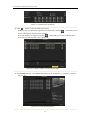
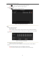
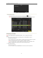
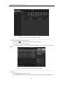
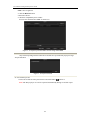
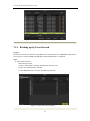
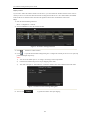
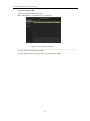
Download Plug-and-Play Series NVR Version 1.0

Transcript
User Manual of Plug-and-Play Series NVR
Plug-and-Play Series NVR
Version 1.0
1
User Manual of Plug-and-Play Series NVR
Regulatory information
FCC information
FCC compliance : This
equipment has been tested and found to comply with the limits for a digital
device, pursuant to part 15 of the FCC Rules. These limits are designed to provide reasonable
protection against harmful interference when the equipment is operated in a commercial
environment. This equipment generates, uses, and can radiate radio frequency energy and, if not
installed and used in accordance with the instruction manual, may cause harmful interference to
radio communications. Operation of this equipment in a residential area is likely to cause harmful
interference in which case the user will be required to correct the interference at his own expense.
FCC conditions
This device complies with part 15 of the FCC Rules. Operation is subject to the following two
conditions:
1. This device may not cause harmful interference.
2. This device must accept any interference received, including interference that may cause
undesired operation.
EU Conformity Statement
This product and - if applicable - the supplied accessories too are marked with "CE" and comply
therefore with the applicable harmonized European standards listed under the Low Voltage
Directive 2006/95/EC, the EMC Directive 2004/108/EC.
2002/96/EC (WEEE directive): Products marked with this symbol cannot be disposed of as
unsorted municipal waste in the European Union. For proper recycling, return this product to your
local supplier upon the purchase of equivalent new equipment, or dispose of it at designated
collection points. For more information see: www.recyclethis.info.
2006/66/EC (battery directive): This product contains a battery that cannot be disposed of as
unsorted municipal waste in the European Union. See the product documentation for specific
battery information. The battery is marked with this symbol, which may include lettering to
indicate cadmium (Cd), lead (Pb), or mercury (Hg). For proper recycling, return the battery to
your supplier or to a designated collection point. For more information see: www.recyclethis.info.
2
User Manual of Plug-and-Play Series NVR
Preventive and Cautionary Tips
Before connecting and operating your device, please be advised of the following tips:
•
•
•
•
•
Ensure unit is installed in a well-ventilated, dust-free environment.
Unit is designed for indoor use only.
Keep all liquids away from the device.
Ensure environmental conditions meet factory specifications.
Ensure unit is properly secured to a rack or shelf. Major shocks or jolts to the unit as a result of dropping it
may cause damage to the sensitive electronics within the unit.
•
•
•
•
Use the device in conjunction with an UPS if possible.
Power down the unit before connecting and disconnecting accessories and peripherals.
A factory recommended HDD should be used for this device.
Improper use or replacement of the battery may result in hazard of explosion. Replace with the same or
equivalent type only. Dispose of used batteries according to the instructions provided by the battery
manufacturer.
3
User Manual of Plug-and-Play Series NVR
Product Key Features
General






Connectable to network cameras, network dome and DVS.
Connectable to the third-party network cameras like AXIS, ONVIF, PANASONIC,
PSIA, SAMSUNG and SANYO.
PAL/NTSC adaptive video inputs.
Each channel supports dual-stream.
Up to 16 network cameras for SK-RN16, and 8 network cameras for
network cameras for SK-RN08, and 8 network cameras for SK-RP08
models. Independent configuration for each channel, including
resolution, frame rate, bit rate, image quality, etc.
The quality of the input and output record is configurable.
Local Monitoring
 Simultaneous HDMI, VGA outputs.



HDMI output and VGA output at up to 1920×1080 resolution.
Multiple screen display in live view is supported, and the display sequence of channels
is adjustable.
Live view screen can be switched in group, and manual switch and automatic cycle

live view are also provided, and the interval of automatic cycle can be adjusted.
Quick setting menu is provided for live view.




Motion detection, tamper-proof, video exception alert and video loss alert functions.
Privacy mask.
Multiple PTZ protocols supported; PTZ preset, patrol and pattern.
Zooming in by clicking the mouse and PTZ tracing by dragging mouse.
HDD Management

8 network disks (8 NAS disks, or 7 NAS disks+1 IP SAN disk) can be connected.

HDD group management.

Support HDD standby function.

HDD quota management; different capacity can be assigned to different channel.
4
User Manual of Plug-and-Play Series NVR
















Backup



Holiday recording schedule configuration.
Normal and event video encoding parameters.
Multiple recording types: manual, normal, alarm, motion, motion | alarm, motion &
alarm.
8 recording time periods with separated recording types.
Pre-record and post-record for alarm, motion detection for recording, and pre-record
time for schedule and manual recording.
Searching record files and captured pictures by events (alarm input/motion detection).
Tag adding for record files, searching and playing back by tags.
Locking and unlocking record files.
Local redundant recording and capture.
Searching and playing back record files by channel number, recording type, start time,
end time, etc.
Motion analysis for the selected area in the video.
Zooming in when playback.
Playing reversely.
Adverse playback of multi-channel.
Supports pause, play reverse, speed up, speed down, skip forward, and skip backward
when playback, and locating by dragging the mouse.
Manual capture, continuous capture of video images and playback of captured pictures.
Export video data by USB, SATA
Export video clips when playback.
Management and maintenance of backup devices.
Alarm and Exception
 Configurable arming time of alarm input/output.
 Alarm for video loss, motion detection, tampering, abnormal signal, video input/output
standard mismatch, illegal login, network disconnected, IP confliction, abnormal
record/capture, HDD error, and HDD full, etc.
 Alarm triggers full screen monitoring, audio alarm, notifying surveillance center,
sending email and alarm output.
 Automatic restore when system is abnormal.
Other Local Functions
 Operable by front panel, mouse, remote control, and control keyboard.
 Three-level user management; admin user is allowed to create many operating
accounts and define their operating permission, which includes the limit to access any
channel.
 Operation, alarm, exceptions and log recording and searching.
 Manually triggering and clearing alarms.
 Import and export of device configuration information.
5
User Manual of Plug-and-Play Series NVR
Network Functions
 2 self-adaptive 10M/100M/1000M network interfaces, and various working modes are
configurable: multi-address, load balance, network fault tolerance, etc.

8 independent PoE network interfaces are provided for SK-RP08,
and 4 independent PoE network interfaces for SK-RP04

IPv6 is supported.

TCP/IP protocol, PPPoE, DHCP, DNS, DDNS, NTP, SADP, SMTP, SNMP, NFS, and

iSCSI are supported.
TCP, UDP and RTP for unicast.
Remote search, playback, download, locking and unlocking of the record files, and
support downloading files broken transfer resume.
Remote parameters setup; remote import/export of device parameters.

Remote viewing of the device status, system logs and alarm status.

Remote keyboard operation.


Remote locking and unlocking of control panel and mouse.
Remote HDD formatting and program upgrading.



Remote system restart and shutdown.
RS-232, RS-485 transparent channel transmission. (RS-232 is not supported by
SK-RP04/SK-RP08 series NVR.)
Alarm and exception information can be sent to the remote host



Remotely start/stop recording.
Remotely start/stop alarm output.
Remote PTZ control.

Remote JPEG capture. (Not supported by SK-RP04/SK-RP08)

Two-way audio and voice broadcasting.

Embedded WEB server.

SDK for Windows and Linux system.


6
User Manual of Plug-and-Play Series NVR
TABLE OF CONTENTS
Product Key Features ...................................................................................................... 4
Chapter 1
Introduction .................................................................................................... 11
1.1 Front Panel ............................................................................................................... 12
1.2 IR Remote Control Operations................................................................................. 20
1.3 USB Mouse Operation ............................................................................................. 22
1.4 Input Method Description ........................................................................................ 23
1.5 Rear Panel ................................................................................................................ 24
Chapter 2
Getting Started ............................................................................................... 30
2.1 Starting Up and Shutting Down the NVR ................................................................ 31
2.2 Using the Wizard for basic configuration ................................................................ 33
2.3 Adding and Connecting the IP Cameras .................................................................. 38
2.3.1
Adding the online IP Cameras.................................................................. 38
2.3.2
Editing the connected IP cameras and Configuring Customized Protocols39
2.3.3
Editing IP cameras connected to the PoE interfaces (Only for
SK-RP04/SK-RP08)
........................................ 41
Chapter 3
Live View ......................................................................................................... 45
3.1 Introduction of Live View ........................................................................................ 46
3.2 Operations in Live View Mode ................................................................................ 47
3.2.1
Front Panel Operation on Live View ........................................................ 47
3.2.2
Using the Mouse in Live View ................................................................. 48
3.2.3
Using an Auxiliary Monitor ..................................................................... 49
3.2.4
Quick Setting Toolbar in Live View Mode .............................................. 50
3.3 Adjusting Live View Settings .................................................................................. 52
3.4 Channel-zero Encoding ............................................................................................ 54
3.5 User Logout.............................................................................................................. 55
Chapter 4
PTZ Controls .................................................................................................. 56
4.1 Configuring PTZ Settings ........................................................................................ 57
4.2 Setting PTZ Presets, Patrols & Patterns ................................................................... 58
4.2.1
Customizing Presets ................................................................................. 58
4.2.2
Calling Presets.......................................................................................... 59
4.2.3
Customizing Patrols ................................................................................. 60
4.2.4
Calling Patrols .......................................................................................... 61
4.2.5
Customizing Patterns ............................................................................... 62
4.2.6
Calling Patterns ........................................................................................ 63
4.3 PTZ Control Toolbar ................................................................................................ 65
Chapter 5
Record and Capture Settings ........................................................................ 66
5.1 Configuring Encoding Parameters ........................................................................... 67
5.2 Configuring Record/Capture Schedule .................................................................... 70
5.3 Configuring Motion Detection Record and Capture ................................................ 74
7
User Manual of Plug-and-Play Series NVR
5.4
5.5
5.6
5.7
5.8
5.9
Configuring Alarm Triggered Record and Capture .................................................. 76
Manual Record and Continuous Capture ................................................................. 78
Configuring Holiday Record and Capture ............................................................... 79
Configuring Redundant Recording and Capture ...................................................... 81
Configuring HDD Group for Recording and Capture .............................................. 83
Files Protection ........................................................................................................ 85
Chapter 6
Playback .......................................................................................................... 88
6.1 Playing Back Record Files ....................................................................................... 89
6.1.1
Playing Back by Channel ......................................................................... 89
6.1.2
Playing Back by Time .............................................................................. 92
6.1.3
Playing Back by Normal Video Search .................................................... 94
6.1.4
Playing Back by Event Search ................................................................. 97
6.1.5
Playing Back by Tag .............................................................................. 100
6.1.6
Playing Back by System Logs ................................................................ 104
6.2 Auxiliary Functions of Playback ............................................................................ 106
6.2.7
Playing Back Frame by Frame ............................................................... 106
6.2.8
Digital Zoom .......................................................................................... 106
6.2.9
Adverse Playback of Multi-channel ....................................................... 107
6.3 Picture Playback ..................................................................................................... 109
Chapter 7
Backup........................................................................................................... 111
7.1 Backing up Record Files ........................................................................................ 112
7.1.1
Quick Export .......................................................................................... 112
7.1.2
Backing up by Normal Video Search ..................................................... 113
7.1.3
Backing up by Event Search .................................................................. 121
7.1.4
Backing up Video Clips.......................................................................... 124
7.2 Backing up Pictures ............................................................................................... 126
7.3 Managing Backup Devices .................................................................................... 129
Chapter 8
Alarm Settings .............................................................................................. 132
8.1 Setting Motion Detection Alarm ............................................................................ 133
8.2 Setting Sensor Alarms ............................................................................................ 135
8.3 Detecting Video Loss Alarm .................................................................................. 138
8.4 Detecting Video Tampering Alarm......................................................................... 140
8.5 Handling Exceptions Alarm ................................................................................... 142
8.6 Setting Alarm Response Actions ............................................................................ 143
8.7 Triggering or Clearing Alarm Output Manually .................................................... 146
Chapter 9
Network Settings .......................................................................................... 147
9.1 Configuring General Settings ................................................................................. 148
9.2 Configuring Advanced Settings ............................................................................. 150
9.2.1
Configuring PPPoE Settings .................................................................. 150
9.2.2
Configuring DDNS ................................................................................ 150
9.2.3
Configuring NTP Server ........................................................................ 153
9.2.4
Configuring SNMP ................................................................................ 154
9.2.5
Configuring Remote Alarm Host ........................................................... 154
9.2.6
Configuring Multicast ............................................................................ 155
8
User Manual of Plug-and-Play Series NVR
9.2.7
Configuring RTSP .................................................................................. 156
9.2.8
Configuring Server and HTTP Ports ...................................................... 156
9.2.9
Configuring Email .................................................................................. 157
9.2.10 Configuring UPnP™ .............................................................................. 158
9.3 Checking Network Traffic...................................................................................... 161
9.4 Configuring Network Detection ............................................................................. 162
9.4.1
Testing Network Delay and Packet Loss ................................................ 162
9.4.2
Exporting Network Packet ..................................................................... 162
9.4.3
Checking the network status .................................................................. 163
9.4.4
Checking Network Statistics .................................................................. 165
Chapter 11
HDD Management ....................................................................................... 185
11.1 Initializing HDDs ................................................................................................... 186
11.2 Managing Network HDD ....................................................................................... 188
11.3 Managing eSATA ................................................................................................... 191
11.4 Managing HDD Group........................................................................................... 192
11.4.1
Setting HDD Groups .............................................................................. 192
11.4.2
Setting HDD Property ............................................................................ 193
11.5 Configuring Quota Mode ....................................................................................... 195
11.6 Checking HDD Status ............................................................................................ 197
11.7 HDD Detection ...................................................................................................... 199
11.8 Configuring HDD Error Alarms ............................................................................. 201
Chapter 12
Camera Settings ........................................................................................... 202
12.1 Configuring OSD Settings ..................................................................................... 203
12.2 Configuring Privacy Mask ..................................................................................... 204
12.3 Configuring Video Parameters ............................................................................... 205
Chapter 13
NVR Management and Maintenance ......................................................... 206
13.1 Viewing System Information ................................................................................. 207
13.1.1
Viewing Device Information .................................................................. 207
13.1.2
13.1.3
13.1.4
Viewing Camera Information ................................................................. 207
Viewing Record Information .................................................................. 208
Viewing Alarm Information ................................................................... 209
9
User Manual of Plug-and-Play Series NVR
13.1.5 Viewing Network Information ............................................................... 209
13.1.6 Viewing HDD Information..................................................................... 210
13.2 Searching & Export Log Files................................................................................ 211
13.3 Importing/Exporting Configuration Files............................................................... 214
13.4 Upgrading System .................................................................................................. 215
13.4.1 Upgrading by Local Backup Device ...................................................... 215
13.4.2 Upgrading by FTP .................................................................................. 215
13.5 Restoring Default Settings ..................................................................................... 217
Chapter 14 Others ............................................................................................................ 218
14.1 Configuring RS-232 Serial Port ............................................................................. 219
14.2 Configuring General Settings ................................................................................. 220
14.3 Configuring DST Settings ...................................................................................... 221
14.4 Configuring More Settings for Device Parameters ................................................ 222
14.5 Managing User Accounts ....................................................................................... 223
14.5.1 Adding a User ........................................................................................ 223
14.5.2 Deleting a User....................................................................................... 226
14.5.3 Editing a User......................................................................................... 226
Appendix ............................................................................................................................... 228
Glossary ......................................................................................................................... 229
FAQ 230
List of Compatible IP Cameras ...................................................................................... 231
List of IP Cameras Supported
............. 231
10
User Manual of Plug-and-Play Series NVR
Chapter 1 Introduction
User Manual of Plug-and-Play Series NVR
1.1 Front Panels
The front panel of NVR is shown in Figure 1.1
Figure 1.1 Front Panel of SK-RP08
Figure 1.2 Description of Control Panel Buttons
No.
1
Name
USB
1/MENU
2ABC/F1
3DEF/F2
2
4GHI/ESC
5JKL/EDIT
SHIFT
6MNO/PLAY
7PQRS/REC
8TUV/PTZ
9WXYZ/PREV
0/A
Function Description
Connect to USB mouse or USB flash memory devices.
Enter numeral “1”;
Access the main menu interface.
Enter numeral “2”
Enter letters “ABC”;
The F1 button can be used to select all items on the list;
In PTZ Control mode, the F1 button can be used to zoom out (zoom-) the PTZ
camera;
In live view or playback mode, the F1 button can be used to switch between main
and spot video output.
Enter numeral “3”;
Enter letters “DEF”;
In PTZ Control mode, the F1 button can be used to zoom in (zoom+) the PTZ
camera;
The F2 button can be used to cycle through tab pages.
Enter numeral “4”;
Enter letters “GHI”;
Exit and back to the previous menu.
Enter numeral “5”;
Enter letters “JKL”;
Delete characters before cursor;
Select the checkbox and ON/OFF switch;
Start/stop record clipping in playback.
Switch of compound keys between the numeric/letter input and functional control.
Enter numeral “6”;
Enter letters “MNO”;
In Playback mode, it is used for direct access to playback interface.
Enter numeral “7”;
Enter letters “PQRS”;
Manual record, for direct access to manual record interface; manually
enable/disable record.
Enter numeral “8”;
Enter letters “TUV”;
Access PTZ control interface.
Enter numeral “9”;
Enter letters “WXYZ”;
Multi-camera display in live view;
In Playback mode or MenuPlaybackTag playback interface, this button can be
used to delete the selected tag.
Enter numeral “0”;
Switch between input methods (upper and lowercase alphabet, symbols and
numeric input).
In Playback mode, this button can be used to add the default tag.
User Manual of Plug-and-Play Series NVR
3
DIRECTION
ENTER
The DIRECTION buttons are used to navigate between different fields and items
in menus.
In Playback mode, the Up and Down button is used to speed up and slow down
recorded video.
In All-day Playback mode, the Left/Right button can be used to select the recorded
video of next/previous day; in Playback by Normal Video Search, the Left/Right
button can
be usedintoany
select
the menu
next/previous
Confirm
selection
of the
modes. Itrecorded
can alsofile.
be used to tick checkbox
In
Live View mode, the directional buttons can be used to cycle through channels.
fields.
In
control
mode,
it can
control
of the
PTZ camera.
In PTZ
Playback
mode,
it can
be used
to the
playmovement
or pause the
video.
In Single-frame Playback mode, pressing the ENTER button will advance the
video by a single frame.
In Auto-switch mode, it can be used to stop /start auto switch.
4
POWER
READY
STATUS
5
Power indicator lights in green when DVR is powered up.
Ready indicator is normally green, indicating that the DVR is functioning properly.
Indicator turns green when DVR is controlled by an IR remote control with the
address from 1~254;
Indicator turns red when the SHIFT button is used;
Indicator does not light when the DVR is controlled by a keyboard or by the IR
remote control with the address of 255;
Indicator turns green when the DVR is controlled by IR remote control (with the
address from 1~254) and keyboard at the same time , and the SHIFT button is not
used;
Indicator turns orange : (a) when the DVR is controlled by IR remote control (with
the address from 1~254) and keyboard at the same time and the SHIFT button is
used as well; (b) when the DVR is controlled by IR remote control (with the
address from 1~254) and the SHIFT button is used.
ALARM
Alarm indicator turns red when a sensor alarm is detected.
HDD
HDD indicator blinks in red when data is being read from or written to HDD.
Tx/Rx
TX/RX indictor blinks in green when network connection is functioning properly.
IR Receiver
Receiver for IR remote control.
User Manual of Plug-and-Play Series NVR
1.2 IR Remote Control Operations
The NVR may also be controlled with the included IR remote control, shown in Figure 1. 7.
Note: Batteries (2×AAA) must be installed before operation.
Figure 1. 7 Remote Control
The keys on the remote control closely resemble the ones on the front panel. See Figure 1. 7.
Table 1. 5 Description of the Soft Keyboard Icons
No.
1
Name
POWER
Description
Power on/off the device.
2
DEV
Enables/Disables Remote Control.
3
Alphanumeric
Buttons:
Same as Alphanumeric buttons on front panel.
4
Same as EDIT/IRIS+ button on front panel.
5
EDIT Button
A Button
Same as A/FOCUS+ button on front panel.
6
REC Button
Same as REC/SHOT button on front panel.
7
PLAY Button
Same as the PLAY/AUTO button on front panel.
20
11
User Manual of Plug-and-Play Series NVR
8
INFO Button
Reserved.
9
VOIP Button
Same as the MAIN/SPOT/ZOOM- button on front panel.
10
MENU Button
Same as the MENU/WIPER button on front panel.
11
PREV Button
Same as the PREV/FOCUS- button on front panel.
12
DIRECTION/ENTER
Same as the DIRECTION/ENTER buttons on front panel.
13
Buttons
PTZ Button
Same as the PTZ/IRIS- button on front panel.
14
ESC Button
Same as the ESC button on front panel.
15
RESERVED
Reserved for future usage.
16
F1 Button
Same as the F1/LIGHT button on front panel.
17
PTZControl Buttons
Buttons to adjust the iris, focus and zoom of a PTZ camera.
18
F2 Button
Same as the F2/AUX button on front panel.
Troubleshooting Remote Control:
Note: Make sure you have installed batteries properly in the remote control. And you have to aim
the remote control at the IR receiver in the front panel.
If there is no response after you press any button on the remote, follow the procedure below to
troubleshoot.
Steps:
1. Go to Menu > Settings > General > More Settings by operating the front control panel or the
mouse.
2. Check and remember NVR ID#. The default ID# is 255. This ID# is valid for all the IR
remote controls.
3. Press the DEV button on the remote control.
4. Enter the NVR ID# you set in step 2.
5. Press the ENTER button on the remote.
If the Status indicator on the front panel turns blue, the remote control is operating properly. If the
Status indicator does not turn blue and there is still no response from the remote, please check the
following:
1. Batteries are installed correctly and the polarities of the batteries are not reversed.
2. Batteries are fresh and not out of charge.
3. IR receiver is not obstructed.
If the remote still can’t function properly, please change a remote and try again, or contact the
device provider.
21
User Manual of Plug-and-Play Series NVR
1.3 USB Mouse Operation
A regular 3-button (Left/Right/Scroll-wheel) USB mouse can also be used with this NVR. To use
a USB mouse:
1. Plug USB mouse into one of the USB interfaces on the front panel of the NVR.
2. The mouse should automatically be detected. If in a rare case that the mouse is not detected,
the possible reason may be that the two devices are not compatible, please refer to the
recommended the device list from your provider.
The operation of the mouse:
Table 1. 6 Description of the Mouse Control
Name
Action
Single-Click
Description
Live view: Select channel and show the quick set menu.
Menu: Select and enter.
Double-Click
Live view: Switch between single-screen and multi-screen.
Click and Drag
PTZ control: pan, tilt and zoom.
Tamper-proof, privacy mask and motion detection: Select
target area.
Digital zoom-in: Drag and select target area.
Live view: Drag channel/time bar.
Right-Click
Single-Click
Live view: Show menu.
Menu: Exit current menu to upper level menu.
Scroll-Wheel
Scrolling up
Live view: Previous screen.
Menu: Previous item.
Scrolling down
Live view: Next screen.
Menu: Next item.
Left-Click
22
User Manual of Plug-and-Play Series NVR
1.4 Input Method Description
Figure 1. 8 Soft Keyboard
Description of the buttons on the soft keyboard:
Table 1. 7 Description of the Soft Keyboard Icons
Icons
Description
English
Numbers
Lowercase/Uppercase
Space
Exit
Icons
23
Description
Capital English
Symbols
Backspace
Enter
User Manual of Plug-and-Play Series NVR
1.5 Rear Panel
Figure 1.9 SK-RN08
Table 1.8 Description of Rear Panel Interface
No.
1
3
4
5
6
7
Item
LAN Interfaces
RS-485
Keyboard
Interface
Power Supply
Power Switch
USB
Ground
HDMI
8
VGA
9
AUDIO IN
Description
Connector for LAN (Local Area Network).
Connector for RS-485 devices. T+ and T- pins connect to R+
and R- pins of PTZ receiver respectively.
12VDC power supply.
Switch for turning on/off the device.
Connects USB disks and devices.
Ground (needs to be connected when NVR starts up).
HDMI video output connector.
DB9 connector for VGA output. Display local video output and
menu.
BNC connector for audio input. (Also for two-way audio)
10
AUDIO OUT
BNC connector for audio output.
2
11
Network Interfaces
with PoE function
Independent 10 /100 Mbps PoE Ethernet interfaces.
24
User Manual of Plug-and-Play Series NVR
Figure 1.10 SK-RN16
Table 1.9 Description of Rear Panel Interface
No.
1
Item
VIDEO OUT
AUDIO OUT
Description
BNC connector for video output.
BNC connector for audio output.
3
4
AUDIO IN
RS-232 Interface
BNC connector for audio input. (Also for voice talk)
Connector for RS-232 devices.
5
VGA
6
7
8
9
HDMI
USB
LAN Interface
RS-485 Interface
DB9 connector for VGA output. Display local video output and
menu.
HDMI video output connector.
Connects USB disks and devices.
Connector for LAN (Local Area Network).
Connector for RS-485 devices. T+ and T- pins connect to R+ and
R- pins of PTZ receiver respectively.
10
11
12
ALARM IN
ALARM OUT
Power Supply
Power Switch
GROUND
2
Connector for alarm input.
Connector for alarm output.
12VDC power supply.
Switch for turning on/off the device.
Ground (needs to be connected when NVR starts up).
User Manual of Plug-and-Play Series NVR
Figure 1.11 SK-RP04
Table 1.10 Description of Rear Panel Interface
No.
Description
2
Item
LAN
Network
Interface
RS-485 Interface
3
4
Power Supply
Power Switch
100~240VAC power supply
Switch for turning on/off the device.
5
USB Interface
6
GND
Ground (needs to be connected when NVR starts up).
7
HDMI Interface
8
VGA Output
HDMI video output connector.
DB9 connector for VGA output. Display local video output
and menu.
9
Audio In
RCA connector for voice talk input
10
Audio Out
RCA connector for audio output
Network
Interfaces
with PoE function
Network interface for the cameras and to provide power over
11
1
Connector for LAN (Local Area Network).
Connects to RS-485 devices.
Universal Serial Bus (USB) ports for additional devices such
as USB mouse and USB Hard Disk Drive (HDD).
Ethernet.
User Manual of Plug-and-Play Series NVR
Chapter 2
Getting Started
30
User Manual of Plug-and-Play Series NVR
2.1 Starting Up and Shutting Down the NVR
Purpose:
Proper startup and shutdown procedures are crucial to expanding the life of the NVR.
Before you start:
Check that the voltage of the extra power supply is the same with the NVR’s requirement, and the
ground connection is working properly.
Starting up the NVR:
Steps:
1. Check the power supply is plugged into an electrical outlet. It is HIGHLY recommended that
an Uninterruptible Power Supply (UPS) be used in conjunction with the device. The Power
indicator LED on the front panel should be red, indicating the device gets the power
supply.
2. Press the POWER button on the front panel. The Power indicator LED should turn blue
indicating that the unit begins to start up.
3. After startup, the Power indicator LED remains blue. A splash screen with the status of the
HDD appears on the monitor. The row of icons at the bottom of the screen shows the HDD
status. ‘X’ means that the HDD is not installed or cannot be detected.
Shutting down the NVR
Steps:
There are two proper ways to shut down the NVR. To shut down the NVR:
• OPTION 1: Standard shutdown
1. Enter the Shutdown menu.
Menu > Shutdown
Figure 2. 1 Shutdown Menu
2. Click the Shutdown button.
3. Click the Yes button.
• OPTION 2: By operating the front panel
1. Press and hold the POWER button on the front panel for 3 seconds.
2. Enter the administrator’s username and password in the dialog box for authentication.
3. Click the Yes button.
Note: Do not press the POWER button again when the system is shutting down.
31
User Manual of Plug-and-Play Series NVR
Rebooting the NVR
In the Shutdown menu, you can also reboot the NVR.
Steps:
1. Enter the Shutdown menu by clicking Menu > Shutdown.
2. Click the Logout button to lock the NVR or the Reboot button to reboot the NVR.
32
User Manual of Plug-and-Play Series NVR
2.2 Using the Wizard for basic configuration
By default, the Setup Wizard starts once the NVR has loaded, as shown in Figure 2. 2.
Figure 2. 2 Start Wizard Interface
Operating the Setup Wizard:
1. The Setup Wizard can walk you through some important settings of the NVR. If you don’t
want to use the Setup Wizard at that moment, click the Cancel button. You can also choose
to use the Setup Wizard next time by leaving the “Start wizard when the device starts?”
checkbox checked.
2. Click Next button on the Wizard window to enter the Login window, as shown in Figure 2.
3.
Figure 2. 3 Login Window
3. Enter the admin password. By default, the password is 12345.
4. To change the admin password, check the New Admin Password checkbox. Enter the new
password and confirm the password in the given fields.
33
User Manual of Plug-and-Play Series NVR
5. Click the Next button to enter the date and time settings window, as shown in Figure 2. 4.
Figure 2. 4 Date and Time Settings
6. After the time settings, click Next button which takes you back to the Network Setup Wizard
window, as shown in Figure 2. 5.
SK-RN08/SK-RN16
34
User Manual of Plug-and-Play Series NVR
SK-RP04/RP08
Figure 2. 5 Network Configuration
35
User Manual of Plug-and-Play Series NVR
Figure 2. 7 HDD Management
7. To initialize the HDD, click the Init button. Initialization removes all the data saved in the
HDD.
8. Click Next button. You enter the Adding IP Camera interface.
9. Click Search to find online IP Camera. Select the IP camera to be added, and click the Add
button.
Figure 2. 8 Search for IP Cameras
10. Click Next button. Configure the recording for the searched IP Cameras.
36
User Manual of Plug-and-Play Series NVR
Figure 2. 9 Record Settings
11. Click Copy to copy the settings to other channels, as shown in Figure 2. 10.
Figure 2. 10 Copy Record Settings
12. Click OK to complete the startup Setup Wizard.
37
User Manual of Plug-and-Play Series NVR
2.3 Adding and Connecting the IP Cameras
2.3.1 Adding the online IP Cameras
Purpose:
The main function of the NVR is to connect the network cameras and record the video got from it.
So before you can get a live view or record of the video, you should add the network cameras to
the connection list of the device.
Before you start:
Ensure the network connection is valid and correct. For detailed checking and configuring of the
network, please see Chapter Checking Network Traffic and Chapter Configuring Network
Detection.
Steps:
1. Enter the Camera Management interface.
Main menu> Camera> Camera
Figure 2. 11 Main Menu
2.
To add the online cameras with same network segment:
1) Click Search to search the online cameras.
Figure 2. 12 Camera Settings Interface
38
User Manual of Plug-and-Play Series NVR
3.
2) Check the checkbox of certain cameras to be added.
3) Click Quick Add to add the camera.
To add other IP cameras:
1) On the left side of the interface, you can enter the IP address, protocol, management port,
user name, password and other information of the IP camera to be added.
2) Click Add to add the camera.
Note: If you check the Synchronize IP Camera checkbox, the default settings of the
NVR for the IP camera is applied to the added camera.
2.3.2 Editing the connected IP cameras and Configuring
Customized Protocols
After the adding of the IP cameras, the basic information of the camera lists in the page, you can
configure the basic setting of the IP cameras.
Steps:
1.
Click the
parameters.
icon to edit the parameters; you can edit the IP address, protocol and other
Figure 2. 13 Edit the Parameters
2. Click apply to save the settings and click OK to exit the editing interface.
To edit more parameters:
1. Click the Advance Set icon.
39
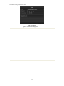
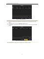
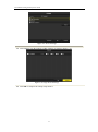
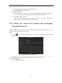
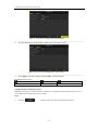
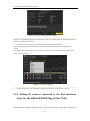
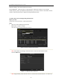
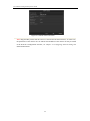
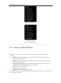
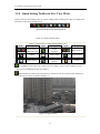
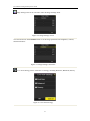
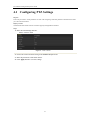
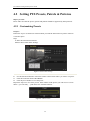
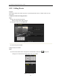
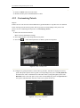
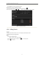
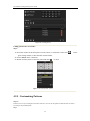
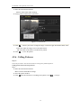
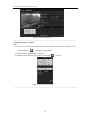
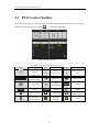
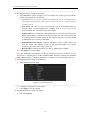
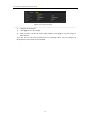
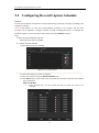
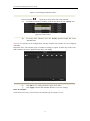
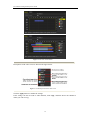
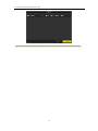
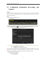
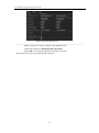
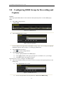
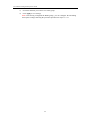
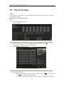
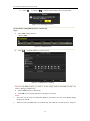
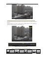
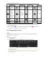
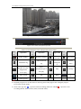
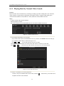
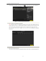
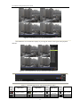
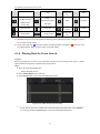
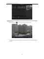
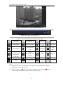
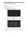
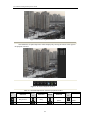
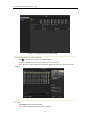
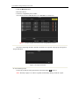
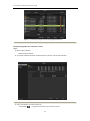
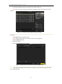
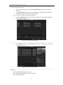
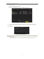
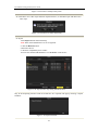
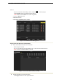
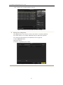
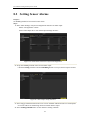
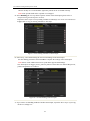
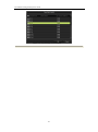
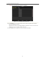
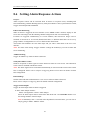
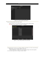
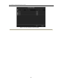
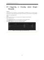
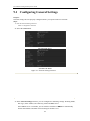
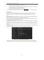
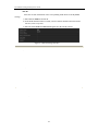
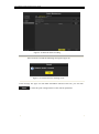
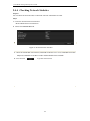
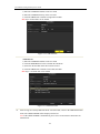
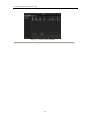
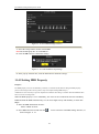
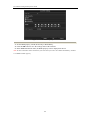
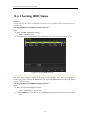
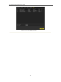
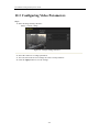
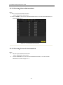
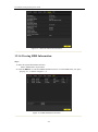
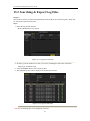
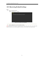
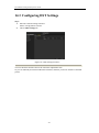
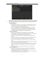
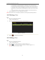
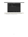
User Manual of Plug-and-Play Series NVR
Figure 2. 14 Network Configuration of the Camera
2.
You can edit the network information and the password of the camera.
Figure 2. 15 Password Configuration of the Camera
3. Click Apply to save the settings and click OK to exit the interface.
Explanation of the icons
Edit basic parameters of the camera
Delete the IP camera
Get the live view of the camera
Configuring the customized protocols
Purpose: To connect the network cameras which are not configured with the standard protocols, you
can configure the customized protocols for them.
Steps:
1.
Click the
button to enter the protocol management interface.
40
User Manual of Plug-and-Play Series NVR
Figure 2. 16 Protocol Management Interface
There are 10 customized protocols provided in the system, you can edit the protocol name; and choose
whether to enable the sub-stream.
2.
Choose the protocol type of transmission and choose the transfer protocols.
Note: The protocol type and the transfer protocols must be supported by the connected network
camera.
After adding the customized protocols, you can see the protocol name is listed in the dropdown list,
please refer to Figure 2. 17.
Figure 2. 17 Protocol Setting
3.
Choose the protocols you just added to validate the connection of the network camera.
2.3.3 Editing IP cameras connected to the PoE interfaces
(Only for SK-RP04/SK-RP08 Plug & Play NVR)
The PoE interfaces enables the NVR system to pass electrical power safely, along with data, on
41
User Manual of Plug-and-Play Series NVR
Ethernet cabling to the connected network cameras.
The SK-RP04/08 NVR provides 4/ 8 PoE interfaces which can connect to 4/8 network
cameras directly; and if you disable the PoE interface, you can also connect to the online network
cameras. And the PoE interface supports the Plug-and-Play function.
To add Cameras for NVR supporting PoE function:
Before you start:
Connect the network cameras via the PoE interfaces.
Steps:
1. Enter the Camera Management interface.
Main menu> Camera> Camera
You can see the connected cameras are listed.
Figure 2. 18 List of Connected Cameras
Note: The cameras connecting to the PoE interface cannot be deleted in this menu.
Click the Edit button.
Figure 2. 19 Edit IP Camera Interface
Note: Plug-and-Play means that the camera is connected to the PoE interface, so in this case,
42
User Manual of Plug-and-Play Series NVR
the parameters of the camera can’t be edited. The IP address of the camera can only be edited
in the Network Configuration interface, see Chapter 9.1 Configuring General Settings for
detailed information.
Note: The cameras connecting to the built-in switch interface cannot be deleted in this menu.
2. Click the Edit button.
43
User Manual of Plug-and-Play Series NVR
Figure 2. 2 Edit IP Camera Interface
Note: Plug-and-Play means that the camera is connected to the PoE interface, so in this case,
the parameters of the camera can’t be edited. The IP address of the camera can only be edited
in the Network Configuration interface, see Chapter 9.1 Configuring General Settings for
detailed information.
44
User Manual of Plug-and-Play Series NVR
Chapter 3
Live View
45
User Manual of Plug-and-Play Series NVR
3.1 Introduction of Live View
Live view shows you the video image getting from each camera in real time. The NVR
automatically enters Live View mode when powered on. It is also at the very top of the menu
hierarchy, thus pressing the ESC many times (depending on which menu you’re on) brings you to
the Live View mode.
Live View Icons
In the live view mode, there are icons at the right top of the screen for each channel, showing the
status of the record and alarm in the channel, so that you can know whether the channel is
recorded, or whether there are alarms occur as soon as possible.
Table 3. 1 Description of Live View Icons
Icons
Description
Alarm (video loss, tampering, motion detection or sensor alarm)
Record (manual record, schedule record, motion detection or alarm triggered
record)
Alarm & Record
46
User Manual of Plug-and-Play Series NVR
3.2 Operations in Live View Mode
In live view mode, there are many functions provided. The functions are listed below.
•
•
•
Single Screen: showing only one screen on the monitor.
Multi-screen: showing multiple screens on the monitor simultaneously.
Auto-switch: the screen is auto switched to the next one. And you must set the dwell time for
each screen on the configuration menu before enabling the auto-switch.
Menu>Configuration>Live View>Dwell Time.
•
•
•
•
Start Recording: normal record and motion detection record are supported.
Output Mode: select the output mode to Standard, Bright, Gentle or Vivid.
All-day Playback: playback the recorded videos for current day.
Aux/Main output switch: the NVR checks the connection of the output interfaces to define
the main and auxiliary output interfaces. The priority level for the main and aux output is
HDMI>VGA>CVBS. This means if the HDMI is used, it will be the main output. If the
HDMI is not used, the VGA output will be the main output. See the table below.
Table 3. 2 Priorities of Interfaces
HDMI
VGA
CVBS
Main output
Auxiliary
output
1
√
√
√
HDMI
VGA
2
√
×
√
HDMI
CVBS
3
×
√
×
√
√
VGA
CVBS
CVBS
4
×

√ means the interface is in use, × means the interface is out of use or the connection is invalid.
And the HDMI, VGA and CVBScan be used at the same time.
When the aux output is enabled, the main output can’t do any operation, and you can do some
basic operation on the live view mode for the Aux output.
Notes:
1. For SK-RN08/SK-RN16, there is only one audio output, the VGA output has a higher priority
over CVBS output. When you enable the audio in both the CVBS and VGA audio output, the
audio from the audio out interface is for VGA.
2. For SK-RP04/SK-RP08, VGA and HDMI output are only supported.
3.2.1 Front Panel Operation on Live View
Note: This function is not supported with SK-RP04/SK-RP08.
Table 3. 3 Front Panel Operation in Live View
Functions
Front Panel Operation
Show single screen
Press the corresponding Alphanumeric button. E.g. Press 2 to display only
the screen for channel 2.
Show multi-screen
Press the PREV/FOCUS- button.
Manually
Next screen: right/down direction button.
switch
47
User Manual of Plug-and-Play Series NVR
screens
Previous screen: left/up direction button.
Auto-switch
Press Enter button.
All-day playback
Press Play button.
Switch
between
main and aux
output
Press Main/Aux button.
3.2.2 Using the Mouse in Live View
Table 3. 4 Mouse Operation in Live View
Name
Description
Menu
Enter the main menu of the system by right clicking the mouse.
Single Screen
Switch to the single full screen by choosing channel number from the
dropdown list.
Multi-screen
Adjust the screen layout by choosing from the dropdown list.
Previous Screen
Switch to the previous screen.
Next Screen
Switch to the next screen.
Start/Stop
Auto-switch
Enable/disable the auto-switch of the screens.
Start Recording
Start normal recording or motion detection recording of all channels.
All-day Playback
Playback the video of the selected channel.
Output Mode
Four modes of output supported, including Standard, Bright, Gentle and
Vivid.
Aux Monitor
Switch to the auxiliary output mode and the operation for the main
output is disabled.
Note: The dwell time of the live view configuration must be set before using Start Auto-switch.
Note: If you enter Aux monitor mode and the Aux monitor is not connected, the mouse operation
is disabled; you need to switch back to the Main output with the MAIN/AUX button on the front
panel or remote.
Note: If the corresponding camera supports intelligent function, the Reboot Intelligence option is
included when right-clicking mouse on this camera.
48
User Manual of Plug-and-Play Series NVR
SK-RN08/SK-RN16
SK-RP04/SK-RP08
Figure 3. 1 Right-click Menu
3.2.3 Using an Auxiliary Monitor
Certain features of the Live View are also available while in an Aux monitor. These features
include:
• Single Screen: Switch to a full screen display of the selected camera. Camera can be
selected from a dropdown list.
• Multi-screen: Switch between different display layout options. Layout options can be
selected from a dropdown list.
• Next Screen: When displaying less than the maximum number of cameras in Live View,
clicking this feature will switch to the next set of displays.
• Playback: Enter into Playback mode.
• PTZ: Enter PTZ Control mode.
• Main Monitor: Enter Main operation mode.
Note: In the live view mode of the main output monitor, the menu operation is not available while
Aux output mode is enabled.
49
User Manual of Plug-and-Play Series NVR
3.2.4 Quick Setting Toolbar in Live View Mode
On the screen of each channel, there is a quick setting toolbar which shows when you single click
the mouse in the corresponding screen.
SK-RN08/SK-RN16/SK-RP04/SK-RP08
Figure 3. 2 Quick Setting Toolbar
Table 3. 5 Description of Quick Setting Toolbar Icons
Icons
/
Description
Enable/Disable
Manual Record
Icons
Description
Instant
Playback
Icons
Description
/
Mute/Audio on
Capture
PTZ Control
Digital Zoom
Image Settings
Live View
Strategy
Close
Instant Playback only shows the record in last five minutes. If no record is found, it means
there is no record during the last five minutes.
Digital Zoom can zoom in the selected area to the full screen. You can left-click and draw to
select the area to zoom in, as shown in Figure 3. 3.
Figure 3. 3 Digital Zoom
50
User Manual of Plug-and-Play Series NVR
Image Settings icon can be selected to enter the Image Settings menu.
Figure 3. 4 Image Settings- Preset
You can also choose the Customize mode to set the image parameters like brightness, contrast,
saturation and hue.
Figure 3. 5 Image Settings- Customize
Live View Strategy can be selected to set strategy, including Real-time, Balanced, Fluency.
Figure 3. 6 Live View Strategy
51
User Manual of Plug-and-Play Series NVR
3.3 Adjusting Live View Settings
Purpose:
Live View settings can be customized according to different needs. You can configure the output
interface, dwell time for screen to be shown, mute or turning on the audio, the screen number for
each channel, etc.
Steps:
1. Enter the Live View Settings interface.
Menu> Configuration> Live View
Figure 3. 7 Live View-General
The settings available in this menu include:
•
Video Output Interface: Designates the output to configure the settings for. Outputs include
HDMI (depends on the model), VGA, Main CVBS and Spot Output.
Notes: No CVBS spot out for SK-RP04/SK-RP08
•
•
Live View Mode: Designates the display mode to be used for Live View.
Dwell Time: The time in seconds to dwell between switching of channels when enabling
auto-switch in Live View.
•
•
•
Enable Audio Output: Enables/disables audio output for the selected video output.
Event Output: Designates the output to show event video.
Full Screen Monitoring Dwell Time: The time in seconds to show alarm event screen.
2. Setting Cameras Order
52
User Manual of Plug-and-Play Series NVR
Figure 3. 8 Live View- Camera Order
To set the camera order:
1) Select a View mode in
.
2) Select the small window, and double-click on the channel number to display the
channel on the window.
You can click
button to start live view for all the channels and click
stop all the live view.
3) Click the Apply button to save the setting.
53
to
User Manual of Plug-and-Play Series NVR
3.4 Channel-zero Encoding
Purpose:
Sometimes you need to get a remote view of many channels in real time from web browser or
CMS(Client Management System) software, in order to decrease the bandwidth requirement
without affecting the image quality, channel-zero encoding is supported as an option for you.
Note: This function is not supported with SK-RP04/SK-RP08.
Steps:
1. Enter the Live View Settings interface.
Menu> Configuration> Live View
2. Select the Channel-Zero Encoding tab.
Figure 3. 9 Live View- Channel-Zero Encoding
3. Check the checkbox after Enable Channel Zero Encoding.
4. Configure the Frame Rate, Max. Bitrate Mode and Max. Bitrate.
After you set the Channel-Zero encoding, you can get a view in the remote client or IE browser of
all the channels in one screen.
54
User Manual of Plug-and-Play Series NVR
3.5 User Logout
Purpose:
After logging out, the monitor turns to the live view mode and if you want to do some operation,
you need to enter user name and password tog in again.
Steps:
1. Enter the Shutdown menu.
Menu>Shutdown
Figure 3. 10 Shutdown
2. Click Logout.
Note: After you have logged out the system, menu operation on the screen is invalid. It is
required to input a user name and password to unlock the system.
55
User Manual of Plug-and-Play Series NVR
Chapter 4 PTZ Controls
56
User Manual of Plug-and-Play Series NVR
4.1 Configuring PTZ Settings
Purpose:
Follow the procedure to set the parameters for PTZ. The configuring of the PTZ parameters should be done before
you control the PTZ camera.
Before you start:
Check that the PTZ and the NVR are connected properly through RS-485 interface.
Steps:
1. Enter the PTZ Settings interface.
Menu >Camera> PTZ
Figure 4. 1 PTZ- General
2. Choose the camera for PTZ setting in the Camera dropdown list.
3. Enter the parameters of the PTZ camera.
4. Click Apply button to save the settings.
57
User Manual of Plug-and-Play Series NVR
4.2 Setting PTZ Presets, Patrols & Patterns
Before you start:
Please make sure that the presets, patrols and patterns should be supported by PTZ protocols.
4.2.1 Customizing Presets
Purpose:
Follow the steps to set the Preset location which you want the PTZ camera to point to when an
event takes place.
Steps:
1. Enter the PTZ Control interface.
Menu>Camera>PTZ>More Settings
Figure 4. 2 PTZ- More Settings
2. Use the directional button to wheel the camera to the location where you want to set preset.
3. Click the round icon before Save Preset.
4. Click the preset number to save the preset.
Repeat the steps2-4 to save more presets. If the number of the presets you want to save is more
than 17, you can click […] and choose the available numbers.
Figure 4. 3 More Presets
58
User Manual of Plug-and-Play Series NVR
4.2.2 Calling Presets
Purpose:
This feature enables the camera to point to a specified position such as a window when an event
takes place.
Call preset in the PTZ setting interface:
Steps:
1. Enter the PTZ Control interface.
Menu>Camera>PTZ>More Settings
2. Check the round icon of Call Preset.
Figure 4. 4 PTZ- Call Preset
3. Choose the preset number.
Call preset in live view mode:
Steps:
1. Press the PTZ button on the front panel or click the PTZ Control icon
setting bar to enter the PTZ setting menu in live view mode.
Figure 4. 5 PTZ Toolbar
59
in the quick
User Manual of Plug-and-Play Series NVR
2. Choose Camera in the list on the menu.
3. Double click the preset in the Preset list to call it.
4.2.3 Customizing Patrols
Purpose:
Patrols can be set to move the PTZ to different key points and have it stay there for a set duration
before moving on to the next key point. The key points are corresponding to the presets. The
presets can be set following the steps above in Customizing Presets.
Steps:
1. Enter the PTZ Control interface.
Menu>Camera>PTZ>More Settings
2. Select patrol number in the drop-down list of patrol.
3. Select the
under Patrol option box to add key points for the patrol.
Figure 4. 6 PTZ- Add Key Point
4. Configure key point parameters, such as the key point No., duration of staying for one key
point and speed of patrol. The key point is corresponding to the preset. The Key Point No.
determines the order at which the PTZ will follow while cycling through the patrol. The
Duration refers to the time span to stay at the corresponding key point. The Speed defines
the speed at which the PTZ will move from one key point to the next.
Figure 4. 7 Key point Configuration
60
User Manual of Plug-and-Play Series NVR
5. Click OK to save the key point to the patrol.
Repeat the above steps to add more key points.
You can also delete all the key points by clicking the trash icon
.
Select a key point, then click
or
button to adjust the order of the key points.
Figure 4. 8 KeyPoints Deletion
4.2.4 Calling Patrols
Purpose:
Calling a patrol makes the PTZ to move according the predefined patrol path.
Calling patrol in the PTZ setting interface:
Steps:
1. In the PTZ setting interface.
Menu> Camera> PTZ> More Settings
2. Select the patrol number, and then click
3. Click
to stop it.
to call the patrol.
61
User Manual of Plug-and-Play Series NVR
Figure 4. 9 Calling Patrol
Calling patrol in live view mode:
Steps:
1. Press PTZ control on the front panel or on the remote, or click PTZ Control icon
on the
quick setting toolbar, to show the PTZ control toolbar.
2. Choose Patrol on the control bar.
3. Double click the patrol or select the patrol and click
to call it.
Figure 4. 10 PTZ Toolbar- Patrol
4.2.5 Customizing Patterns
Purpose:
Patterns can be set by recording the movement of the PTZ. You can call the pattern to make the PTZ movement
according to the predefined path.
Steps:
62
User Manual of Plug-and-Play Series NVR
1. Enter the PTZ Control interface.
Menu>Camera>PTZ>More Settings
2. Choose pattern number in the option box.
Figure 4. 11 PTZ- Pattern
3. Click
and use your mouse to drag the image or click the eight directional buttons in the
control box under the image to move the PTZ camera.
The movement of the PTZ is recorded as the pattern.
4. Click
to save the pattern.
4.2.6 Calling Patterns
Purpose:
Follow the procedure to move the PTZ camera according to the predefined patterns.
Calling pattern in the PTZ setting interface
Steps:
1. Enter the PTZ Control interface.
Menu>Camera>PTZ>More Settings
2. Select the pattern number.
3. Click
, then the PTZ moves according to the pattern. Click
63
to stop it.
User Manual of Plug-and-Play Series NVR
Figure 4. 12 PTZ- Calling Pattern
Call pattern in live view mode.
Steps:
1. In the live view mode, press PTZ control on the front panel or on the remote control, or click
PTZ Control icon
on the quick setting toolbar.
2. And then choose Pattern on the control bar.
3. Double click the pattern or select the pattern and click
Figure 4. 13 PTZ Toolbar- Pattern
64
to call it.
User Manual of Plug-and-Play Series NVR
4.3 PTZ Control Toolbar
In the Live View mode, you can press the PTZ Control button on the front panel or on the remote
control, or choose the PTZ Control icon
to enter the PTZ toolbar.
Figure 4. 14 PTZ Toolbar
Table 4. 1 Description of the PTZ toolbar icons
Icon
Description
Direction button
and the
auto-cycle button
The speed of the
PTZ movement
Icon
Description
Description
Zoom+,
Focus+, Iris+
Zoom-, Focus-,
Iris-
Light on/off
Wiper on/off
Image
Centralization
3D-Zoom
Icon
Preset
Patrol
Pattern
Menu
Previous item
Next item
Start
pattern/patrol
Stop the patrol or
pattern movement
Minimize
windows
Exit
65
User Manual of Plug-and-Play Series NVR
Chapter 5 Record and Capture Settings
66
User Manual of Plug-and-Play Series NVR
5.1 Configuring Encoding Parameters
Purpose:
By configuring the encoding parameters you can define the parameters which affect the image quality, such as the
transmission stream type, the resolution and so on.
Before you start:
1. Make sure that the HDD has already been installed. If not, please install a HDD and initialize
it. (Menu>HDD>General)
Figure 5. 1 HDD- General
2. Check the storage mode of the HDD
1) Click Advanced to check the storage mode of the HDD.
2) If the HDD mode is Quota, please set the maximum record capacity and maximum picture
capacity. For detailed information, see Chapter Configuring Quota Mode.
3) If the HDD mode is Group, you should set the HDD group. For detailed information, see
Chapter Configuring HDD Group for Recording and Capture.
Figure 5. 2 HDD- Advanced
Steps:
1. Enter the Record settings interface to configure the encoding parameters:
Menu>Record>Encoding
Figure 5. 3 Record Encoding
67
User Manual of Plug-and-Play Series NVR
2. Encoding Parameters Setting for Recording
1) Select Record tab page to configure. You can configure the stream type, the resolution,
and other parameters on your demand.
• Pre-record: The time you set to record before the scheduled time or event. For example, when an
alarm triggered the recording at 10:00, if you set the pre-record time as 5 seconds, the camera
records it at 9:59:55.
• Post-record: The time you set to record after the event or the scheduled time. For
example, when an alarm triggered the recording ends at 11:00, if you set the
post-record time as 5 seconds, it records till 11:00:05.
• Expired Time: The expired time is the longest time for a record file to be kept in the
HDD, if the deadline is reached, the file will be deleted. You can set the expired time
to 0, and then the file will not be deleted. The actual keeping time for the file should
be determined by the capacity of the HDD.
• Redundant Record/ Capture: Enabling redundant record or capture means you
save the record and captured picture in the redundant HDD. See Chapter
Configuring Redundant Recording and Capture.
• Record Audio: Check the checkbox to enable or disable audio recording.
2) Click Apply to save the settings.
Note: The redundant record/capture is to decide whether you want the camera to save the
record files or captured pictures in the redundant HDD. You must configure the redundant
HDD in HDD settings. For detailed information, see Chapter 12.4.2 Setting HDD Property.
3. Encoding Parameters Settings for Sub-stream
1) Enter the Sub-stream tab page.
Figure 5. 4 Substream Encoding
2) Configure the parameters of the camera.
3) Click Apply to save the settings.
4. Encoding Parameters Settings for Capture
1) Select the Capture.
68
User Manual of Plug-and-Play Series NVR
Figure 5. 5 Capture Encoding
2)
3)
4)
Configure the parameters.
Click Apply to save the settings.
If the parameters can also be used to other channels, click Copy to copy the settings to
other channels.
Note: The interval is the time period between two capturing actions. You can configure all
the parameters on this menu on your demand.
69
User Manual of Plug-and-Play Series NVR
5.2 Configuring Record/Capture Schedule
Purpose:
Set the record schedule, and then the camera automatically starts/stops recording according to the
configured schedule.
Note: In this chapter, we take the record schedule procedure as an example, and the same
procedure can be applied to configure schedule for both recording and capture. To schedule the
automatic capture, you need to choose the Capture tab in the Schedule interface.
Steps:
1. Enter the Record Schedule interface.
Menu>Record/Capture>Schedule
2. Configure Record Schedule
1) Select Record/Capture Schedule.
Figure 5. 6 Record Schedule
2) Choose the camera you want to configure.
3) Select the check box after the Enable Schedule item.
4) Click Edit button or click on the color icon under the edit button and draw the schedule
line on the panel.
Edit the schedule:
I. In the message box, you can choose the day to which you want to set
schedule.
70
User Manual of Plug-and-Play Series NVR
Figure 5. 7 Recording Schedule Interface
You can click the
button to set the accurate time of the schedule.
II. To schedule an all-day recording, check the checkbox after the All Day item.
Figure 5. 8 Edit Schedule
III.
To arrange other schedule, leave the All Day checkbox blank and set the
Start/End time.
Note: Up to 8 periods can be configured for each day. And the time periods can’t be overlapped
each other.
Repeat the above edit schedule steps to schedule recording or capture for other days in the week.
If the schedule can also be applied to other days, click Copy.
Figure 5. 9 Copy Schedule to Other Days
IV. Click OK to save setting and back to upper level menu.
V. Click Apply in the Record Schedule interface to save the settings.
Draw the schedule:
Click on the color icons, you can choose the schedule type as normal or event.
71
User Manual of Plug-and-Play Series NVR
Figure 5. 10 Draw the Schedule
Descriptions of the color icons are shown in the figure below.
Figure 5. 11 Descriptions of the color icons
Click the Apply button to validate the settings.
If the settings can also be used to other channels, click Copy, and then choose the channel to
which you want to copy.
72
User Manual of Plug-and-Play Series NVR
Figure 5. 12 Copy Schedule to Other Channels
73
User Manual of Plug-and-Play Series NVR
5.3 Configuring Motion Detection Record and
Capture
Purpose:
Follow the steps to set the motion detection parameters. In the live view mode, once a motion
detection event takes place, the NVR can analyze it and do many actions to handle it. Enabling
motion detection function can trigger certain channels to start recording, or trigger full screen
monitoring, audio warning, notify the surveillance center and so on. In this chapter, you can
follow the steps to schedule a record which triggered by the detected motion.
Steps:
1. Enter the Motion Detection interface.
Menu>Camera>Motion
Figure 5. 13 Motion Detection
2.
Configure Motion Detection:
1) Choose camera you want to configure.
2) Check the checkbox after Enable Motion Detection.
3) Drag and draw the area for motion detection by mouse. If you want to set the
motion detection for all the area shot by the camera, click Full Screen. To clear
the motion detection area, click Clear.
74
User Manual of Plug-and-Play Series NVR
Figure 5. 14 Motion Detection- Mask
4) Click Handling, and the message box for channel information pop up.
Figure 5. 15 Motion Detection Handling
3.
5) Select the channels which you want the motion detection event to trigger recording.
6) Click Apply to save the settings.
7) Click OK to back to the upper level menu.
8) Exit the Motion Detection menu.
Edit the Motion Detection Record Schedule. For the detailed information of schedule
configuration, see Chapter Configuring Record/Capture Schedule.
75
User Manual of Plug-and-Play Series NVR
5.4 Configuring Alarm Triggered Record and
Capture
Purpose:
Follow the procedure to configure alarm triggered recording or capture.
Steps:
1. Enter the Alarm setting interface.
Menu> Configuration> Alarm
Figure 5. 16 Alarm Settings
2.
Click Alarm Input.
Figure 5. 17 Alarm Settings- Alarm Input
1) Select Alarm Input number and configure alarm parameters.
2) Choose N.O (normally open) or N.C (normally closed) for alarm type.
3) Check the checkbox for Setting .
4) Click Handling.
76
User Manual of Plug-and-Play Series NVR
Figure 5. 18 Alarm Handling
5) Choose the alarm triggered recording channel.
6) Check the checkbox to select channel.
7) Click Apply to save settings.
8) Click OK to back to the upper level menu.
Repeat the above steps to configure other alarm input parameters.
If the settings can also be applied to other alarm inputs, click Copy and choose the alarm input
number.
Figure 5. 19 Copy Alarm Input
3.
Edit the Alarm triggered record in the Record/Capture Schedule setting interface. For the
detailed information of schedule configuration, see Chapter Configuring Record/Capture
Schedule.
77
User Manual of Plug-and-Play Series NVR
5.5 Manual Record and Continuous Capture
Purpose:
Follow the steps to set parameters for the manual record and continuous capture. Using manual
record and continuous capture, you need to manually cancel the record and capture. The manual
recording and manual continuous capture is prior to the scheduled recording and capture.
Steps:
1. Enter the Manual settings interface.
Menu> Manual
Or press the REC/SHOT button on the front panel.
Figure 5. 20 Manual Record
2.
3.
4.
Enabling Manual Record
1) Select Record on the left bar.
2) Click the status button before camera number to change
to .
Disable manual record.
Click the status button to change
to .
Note: Green icon
means that the channel is configured the record schedule. After
rebooting all the manual records enabled are canceled.
Enabling and disabling the continuous capture
1) Select Continuous Capture on the left bar.
Figure 5. 21 Continuous Capture
2) Click the status button before camera number to change
to .
3) Disable continuous capture.
4) Click the status button to change
to .
Note: Green icon
means that the channel is configured the capture schedule. After rebooting,
all the continuous capture will be canceled.
78
User Manual of Plug-and-Play Series NVR
5.6 Configuring Holiday Record and Capture
Purpose:
Follow the steps to configure the record or capture schedule on holiday for that year. You may
want to have different plan for recording and capture on holiday.
Steps:
1. Enter the Record setting interface.
Menu>Record> Holiday
Figure 5. 22 Holiday Settings
2.
Enable Edit Holiday schedule.
1)
Click
to enter the Edit interface.
Figure 5. 23 Edit Holiday Settings
2)
Check the checkbox after Enable Holiday.
79
User Manual of Plug-and-Play Series NVR
3)
3.
Select Mode from the dropdown list.
There are three different modes for the date format to configure holiday schedule.
4) Set the start and end date.
5) Click Apply to save settings.
6) Click OK to exit the Edit interface.
Enter Record/Capture Schedule settings interface to edit the holiday recording schedule.
See Chapter 6.2 Configuring Record/Capture Schedule.
80
User Manual of Plug-and-Play Series NVR
5.7 Configuring Redundant Recording and
Capture
Purpose:
Enabling redundant recording and capture, which means saving the record files and captured
pictures not only in the R/W HDD but also in the redundant HDD, will effectively enhance the
data safety and reliability. .
Steps:
1. Enter HDD Information interface.
Menu> HDD
Figure 5. 24 HDD General
2. Select the HDD and click
to enter the Local HDD Settings interface.
1) Set the HDD property to Redundancy.
Figure 5. 25 HDD General-Editing
2) Click Apply to save the settings.
3) Click OK to back to the upper level menu.
Note: You must set the Storage mode in the HDD advanced settings to Group before you set the
HDD property to Redundant. For detailed information, please refer to Chapter 12.4 Managing
HDD Group. There should be at least another HDD which is in Read/Write status.
3. Enter the Record setting interface.
Menu> Record> Encoding
1)Select Record tab.
81
User Manual of Plug-and-Play Series NVR
Figure 5. 26 Encoding Record
2)Select Camera you want to configure in the drop-down list.
3)Check the checkbox of Redundant Record/Capture.
4)Click OK to save settings and back to the upper level menu.
Repeat the above steps for configuring other channels.
82
User Manual of Plug-and-Play Series NVR
5.8 Configuring HDD Group for Recording and
Capture
Purpose:
You can group the HDDs and save the record files and captured pictures in certain HDD group.
Steps:
1. Enter HDD setting interface.
Menu>HDD
Figure 5. 27 HDD General
2.
Select Advanced on the left bar.
Figure 5. 28 Storage Mode
Check whether the storage mode of the HDD is Group. If not, set it to Group. For detailed
information, please refer to Chapter 12.4 Managing HDD Group.
3. Select General in the left bar.
Click
to enter editing interface.
4. Configuring HDD group.
1) Choose a group number for the HDD group.
2) Click Apply and then in the pop-up message box, click Yes to save your settings.
3) Click OK to back to the upper level menu.
Repeat the above steps to configure more HDD groups.
5. Choose the Channels which you want to save the record files and captured pictures in the
HDD group.
1) Select Advanced on the left bar.
Figure 5. 29 HDD Advanced
2)
Choose Group number in the dropdown list of Record on HDD Group
83
User Manual of Plug-and-Play Series NVR
3)
4)
Check the channels you want to save in this group.
Click Apply to save settings.
Note: After having configured the HDD groups, you can configure the Recording
and Capture settings following the procedure provided in Chapter 5.2-5.7.
84
User Manual of Plug-and-Play Series NVR
5.9 Files Protection
Purpose:
You can lock the recorded files or set the HDD property to Read-only to protect the record files
from being overwritten.
Protect file by locking the record files:
Steps:
1. Enter Playback setting interface.
Menu> Playback
Figure 5. 30 Playback
2.
3.
4.
Select the channels you want to investigate by checking the checkbox to
Configure the record type, file type start/end time.
Click Search to show the results.
.
Figure 5. 31 Playback- Search Result
5.
Protect the record files.
1) Find the record files you want to protect, and then click the
icon which will
turn to , indicating that the file is locked.
Note: The record files of which the recording is still not completed can’t be locked.
85
User Manual of Plug-and-Play Series NVR
2)
Click
to change it to
to unlock the file and the file is not protected.
Figure 5. 32 Unlocking Attention
Protect file by setting HDD property to Read-only
Steps:
1. Enter HDD setting interface.
Menu> HDD
Figure 5. 33 HDD General
2.
Click
to edit the HDD you want to protect.
Figure 5. 34 HDD General- Editing
Note: To edit HDD property, you need to set the storage mode of the HDD to Group. See
Chapter Managing HDD Group.
3. Set the HDD property to Read-only.
4. Click OK to save settings and back to the upper level menu.
Notes:
1. You can’t save any files in a Read-only HDD. If you want to save files in the HDD, change
the property to R/W.
2. If there is only one HDD and is set to Read-only, the NVR can’t record any files. Only live
86
User Manual of Plug-and-Play Series NVR
saved in next R/W HDD. If there is only one HDD, the recording will be stopped.
87
User Manual of Plug-and-Play Series NVR
Chapter 6 Playback
88
User Manual of Plug-and-Play Series NVR
6.1 Playing Back Record Files
6.1.1 Playing Back by Channel
Purpose:
Play back the recorded video files of a specific channel in the live view mode. Channel switch is
supported.
Instant playback by channel
Steps:
Choose a channel in live view mode using the mouse and click the
button in the quick
setting toolbar.
Note: In the instant playback mode, only record files recorded during the last five minutes on
this channel will be played back.
Figure 6. 1 Instant Playback Interface
All-day Playback by channel
1. Enter the All-day Playback interface.
Mouse: right click a channel in live view mode and select All-day Playback from the menu, as
shown in Figure 6. 2.
89
User Manual of Plug-and-Play Series NVR
SK-RN08/SK-RN16
SK-RP04/SK-RP08
Figure 6. 2 Right-click Menu under Live View
Front Panel: press PLAY button to play back record files of the channel under single-screen live
view mode.
Under multi-screen live view mode, the recorded files of the top-left channel will be played back.
Note: Pressing numerical buttons will switch playback to the corresponding channels during
playback process.
2. Playback management.
The toolbar in the bottom part of Playback interface can be used to control playing
progress, as shown in Figure 6. 3.
90
User Manual of Plug-and-Play Series NVR
Figure 6. 3 All-day Playback Interface
The channel and time selection menu displays by moving the mouse to the right of the playback
interface.
Click the channel(s) if you want to switch playback to another channel or execute simultaneous
playback of multiple channels, as shown in Figure 6. 4 .
Figure 6. 4 All-day Playback Interface with Channel List
Figure 6. 5 Toolbar of All-day Playback
Table 6. 1 Detailed Explanation of All-day-playback Toolbar
Butto
n
Operation
Button
Operation
/
Audio
/
Start/Stop
91
Button
Operation
30s forward
Button
Operatio
n
30s
User Manual of Plug-and-Play Series NVR
/
on/Mute
clipping
Add
default tag
Add
customized
tag
Tag
managemen
t
Speed
down
Pause
reverse
play/
Reverse
play/
Single-fram
e reverse
play
Pause
play/Play/Si
ngle-frame
play
Stop
Speed up
Previous
day
Next day
Hide
Exit
Process bar
Video type
bar
/
reverse
Note:
1. Playback progress bar: use the mouse to click any point of the progress bar or drag the progress
bar to locate special frames.
2. About video type bar:
represents normal recording (manual or schedule); represents event
recording (motion, alarm, motion | alarm, motion & alarm).
6.1.2 Playing Back by Time
Purpose:
Play back video files recorded in specified time duration. Multi-channel simultaneous playback
and channel switch are supported.
Steps:
1. Enter playback interface.
Menu>Playback
2. Set search conditions and click the Playback button to enter Playback interface.
Figure 6. 6 Video Search by Time
In the Playback interface:
The toolbar in the bottom part of Playback interface can be used to control playing process,
as shown in Figure 6. 7.
92
User Manual of Plug-and-Play Series NVR
Figure 6. 7 Interface of Playback by Time
Figure 6. 8 Toolbar of Playback by Time
Table 6. 2 Detailed Explanation of Playback-by-time Toolbar
Butto
n
Operation
Butto
n
Operation
/
Audio on/Mute
/
Start/Stop clipping
30s
forward
30s reverse
Add default tag
Add customized
tag
Tag
manageme
nt
Speed
down
Pause reverse
play/Reverse play/
Single-frame
reverse play
Pause
play/Play/Single-fr
ame play
Stop
Speed up
Exit
Hide
Progress
bar
/
Video search
/
Butto
n
Operation
Butto
n
Operation
Video type bar
Note:
1. Playback progress bar: use the mouse to click any point of the progress bar or drag the progress
bar to locate special frames.
2. About video type bar:
represents normal recording (manual or schedule); represents event
recording (motion, alarm, motion | alarm, motion & alarm).
93
User Manual of Plug-and-Play Series NVR
6.1.3 Playing Back by Normal Video Search
Purpose:
Play back video files searched out by restricting recording type and recording time. The video files
in the result list are played back sequentially and channel switch is supported. Recording types
contain Normal, Motion, Alarm, Motion / Alarm, Motion & Alarm, Manual and All.
Steps:
1. Enter Normal Video Search interface.
Menu>Playback>Normal
Set search condition and click Search button to enter the Search Result interface.
Figure 6. 9 Normal Video Search
2. Check detail information of record files.
If you want to know the record information of every camera, click Detail button and will pop
up a window to show them, as shown in Figure 6. 10.
Click
or
can switch to the previous or next page.
Click Previous or Next button can switch to the date before or after the present date.
Click
or
at the left-top of the window can zoom in or out of the time bar
Figure 6. 10 Record Information
3. Choose a record file you want to play back.
If there is only one channel in the search result, clicking
Playback interface of this channel.
94
button takes you to Full-screen
User Manual of Plug-and-Play Series NVR
If more than one channel is optional, clicking
button takes you to step 3and step 4.
Figure 6. 11 Result of Normal Video Search
4. Choose channels for simultaneous playback.
Note: Optional channels for simultaneous playback are the same as the channels chosen to
search record files in step 1. And the channel with the recorded file selected in step 2 is the
main channel during multi-channel playback and it is displayed at the upper left corner.
4-ch, 8-ch and 16-ch devices support 4-ch, 8-ch and 16-ch simultaneous playback
respectively.
Figure 6. 12 Select Channels for Synchronous Playback
5. Synchronous Playback interface.
The toolbar in the bottom part of Playback interface can be used to control playing process.
95
User Manual of Plug-and-Play Series NVR
Figure 6. 13 4-ch Synchronous Playback Interface
The hidden list of recorded files displays by moving the mouse to the right of the playback
interface.
Figure 6. 14 4-ch Synchronous Playback Interface with Video List
Figure 6. 15 Toolbar of Normal Playback
Table 6. 3 Detailed Explanation of Normal Playback Toolbar
Butto
n
Operation
Butto
n
Operation
/
Audio on/Mute
/
Start/Stop clipping
30s
forward
30s reverse
Add customized
Tag
Speed
Add default tag
96
Butto
n
Operation
Butto
n
Operation
User Manual of Plug-and-Play Series NVR
tag
/
manageme
nt
down
Pause
play/Play/Single-fr
ame play
Stop
Speed up
Previous file
Next file
Video
search
Exit
Hide toolbar
Progress bar
Pause reverse
play/Reverse play/
Single-frame
reverse play
/
Video type
bar
Note:
1. Playback progress bar: use the mouse to click any point of the progress bar or drag the progress
bar to locate special frames.
2. About video type bar: represents normal recording (manual or schedule); represents event
recording (motion, alarm, motion | alarm, motion & alarm).
6.1.4 Playing Back by Event Search
Purpose:
Play back record files on one or several channels searched out by restricting event type (e.g. alarm
input and motion detection). Channel switch is supported.
Steps:
1. Enter the Event Search interface.
Menu>Playback>Event
2. Select Alarm Input as the event type.
3. Click Search button to enter the Search Result interface.
Figure 6. 16 Video Search by Alarm Input
If you want to play back recorded files associated with motion detection, choose Motion
as event type and click Search button to enter the Search Result interface.
97
User Manual of Plug-and-Play Series NVR
Figure 6. 17 Video Search by Motion
4. Click
button to enter the Playback interface.
If there is only one channel is triggered by an alarm input, clicking
Full-screen Playback interface of this channel.
button takes you to
If several channels are triggered, clicking
button takes you to step 7and then step 8.
Note: Pre-play and post-play can be configured.
Figure 6. 18 Result of Video Search by Alarm Input
5. Click Details button to view detailed information of the record file, e.g. start time, end time,
file size, etc.
Figure 6. 19 Event Details Interface
98
User Manual of Plug-and-Play Series NVR
6. Playback interface.
The toolbar in the bottom part of Playback interface can be used to control playing
process.
Figure 6. 20 Interface of Playback by Event
The hidden list of events will be displayed by moving the mouse to the right of the
playback interface.
Figure 6. 21 Playback Interface with Alarm Input List
Figure 6. 22 Toolbar of Playback by Event
Table 6. 4 Detailed Explanation of Playback-by-event Toolbar
Butto
n
Operation
Butto
n
Operation
/
Audio on/Mute
/
Start/Stop clipping
99
Butto
n
Operation
30s
Butto
n
Operation
30s reverse
User Manual of Plug-and-Play Series NVR
forward
/
Add default tag
Add customized
tag
Tag
manageme
nt
Speed
down
Pause reverse
play/Reverse play/
Single-frame
reverse play
Pause
play/Play/Single-fr
ame play
Stop
Speed up
Previous event
Next event
Event
search
Exit
Hide
Progress bar
Video type
bar
/
Note:
1. Playback progress bar: use the mouse to click any point of the progress bar or drag the progress
bar to locate special frames.
2. About video type bar: represents normal recording (manual or schedule); represents event
recording (motion, alarm, motion | alarm, motion & alarm).
6.1.5 Playing Back by Tag
Purpose:
Video tag allows you to record related information like people and location of a certain time point
during playback. You are also allowed to use video tag(s) to search for record files and position
time point.
Before playing back by tag:
1. Enter Playback interface.
Figure 6. 23 Interface of Playback by Time
Click
button to add default tag.
100
User Manual of Plug-and-Play Series NVR
Click
button to add customized tag and input tag name.
Note: Max. 64 tags can be added to a single video file.
2. Tag management.
Click
button to check, edit and delete tag(s).
Figure 6. 24 Tag Management Interface
Steps:
1. Enter Tag Search interface.
Menu>Playback>Tag
Choose channels, tag type and time, and click Search to enter Search Result interface.
Note: Two tag types are selectable: All and Tag Keyword. Input keyword if you choose
Tag Keyword.
Figure 6. 25 Video Search by Tag
2. Set playback conditions and tag management.
Choose the tag name of the recorded file you want to play back; it can be edited or
deleted.
Pre-play and post-play time can be set according to actual needs.
Note: Pre-play time and post-play time is added to the time point of the tag.
101
User Manual of Plug-and-Play Series NVR
Figure 6. 26 Result of Video Search by Tag
3. Playback by tag.
Choose a tag and click
button to play back the related record file.
Figure 6. 27 Interface of Playback by Tag
The hidden list of tags will be displayed by moving the mouse to the right of the playback
interface.
102
User Manual of Plug-and-Play Series NVR
Figure 6. 28 Interface of Playback by Tag with Video List
Figure 6. 29 Toolbar of Playback by Tag
Table 6. 5 Detailed Explanation of Playback-by-tag Toolbar
Butto
n
Operation
Butto
n
Operation
/
Audio on/Mute
/
Start/Stop clipping
30s
forward
30s reverse
Add default tag
Add customized
tag
Tag
manageme
nt
Speed
down
Pause reverse
play/Reverse play/
Single-frame
reverse play
Pause
play/Play/Single-fr
ame play
Stop
Speed up
Next tag
Tag search
Exit
/
Previous tag
Hide
/
Progress bar
Butto
n
Operation
Butto
n
Operation
Video type
bar
Note:
1. Playback progress bar: use the mouse to click any point of the progress bar or drag the
progress bar to locate special frames.
2. About video type bar:
represents normal recording (manual or schedule); represents
event recording (motion, alarm, motion | alarm, motion & alarm).
103
User Manual of Plug-and-Play Series NVR
6.1.6 Playing Back by System Logs
Purpose:
Play back record file(s) associated with channels after searching system logs.
Steps:
1. Enter Log Information interface.
Menu>Maintenance>Log Information
2. Click Log Search tab to enter Playback by System Logs.
Set search time and type and click Search button.
Figure 6. 30 System Log Search Interface
3. Choose a log with record file and click
button to enter Playback interface.
Note: If there is no record file at the time point of the log, the message box “no related
record file” will pop up.
Figure 6. 31 Result of System Log Search
4. Playback interface.
The toolbar in the bottom part of Playback interface can be used to control playing process.
104
User Manual of Plug-and-Play Series NVR
Figure 6. 32 Interface of Playback by Log
105
User Manual of Plug-and-Play Series NVR
6.2 Auxiliary Functions of Playback
6.2.7 Playing Back Frame by Frame
Purpose:
Play video files frame by frame, in case of checking image details of the video when abnormal
events happen.
Steps:
• Using a Mouse:
Go to Playback interface.
If you choose playback of the record file: click button
until the speed changes to Single
frame and one click on the playback screen represents playback of one frame.
If you choose adverse playback of the record file: click button
until the speed changes to
Single frame and one click on the playback screen represents adverse playback of one frame. It is
also feasible to use button
in toolbar.
6.2.8 Digital Zoom
Steps:
1. Right click the mouse on a channel under playback and choose Digital Zoom to enter Digital
Zoom interface.
2. Drag and draw the red rectangle and the image within it will be quadrupled.
106
User Manual of Plug-and-Play Series NVR
Figure 6. 33 Draw Area for Digital Zoom
Figure 6. 34 Right-click Menu under Playback
The right-click menu:
Note: This menu differs slightly from one playback interface to another.
Table 6. 6 Detailed Explanation of Right-click Menu under Playback
Button
Function
Return to Search interface
Enter Digital Zoom interface
Show & hide control interface
Return to Playback interface
6.2.9 Adverse Playback of Multi-channel
Purpose:
You can play back record files of multi-channel adversely. Up to 16-ch (with 1280*720 resolution)
simultaneous adverse playback is supported; up to 4-ch (with 1920*1080P resolution)
simultaneous adverse playback is supported and up to 1-ch (with 2560*1920 resolution) adverse
playback is supported.
following settings.
Steps:
1. Enter Playback interface.
Menu>Playback
107
User Manual of Plug-and-Play Series NVR
2. Set the search condition and click Search to enter the Search Result interface.
3. If more than one channel is optional, click
playback.
to choose channels for simultaneous
Figure 6. 35 Select Channels for Synchronous Playback
4. Check
checkbox to select the channel(s) and click OK to confirm the settings and enter
the synchronous playbck interface.
Figure 6. 36 4-ch Synchronous Playback Interface
Click
to play back the record files adversely.
108
User Manual of Plug-and-Play Series NVR
6.3 Picture Playback
Note: The SK-RP04/SK-RP08 series does not support this function.
Purpose:
Search and view captured pictures stored in HDD.
Steps:
1. Enter Picture Search interface.
Menu>Playback>Picture
Set channel, picture type and time and click
button to enter Search Result
interface.
Note: Picture types include Normal, Motion, Alarm, Motion / Alarm, Motion & Alarm,
Capture and Continuous Capture.
Figure 6. 37 Picture Search
2. View pictures.
Choose a picture you want to view and click
button.
Figure 6. 38 Result of Picture Search
3. Picture Playback interface.
The toolbar in the bottom part of Playback interface can be used to control playing process.
109
User Manual of Plug-and-Play Series NVR
Figure 6. 39 Picture Playback Interface
The hidden list of captured pictures will be displayed by moving the mouse to the right of
the playback interface.
Figure 6. 40 Playback Interface with Picture List
Figure 6. 41 Picture Playback Toolbar
Table 6. 7 Detailed Explanation of Picture-playback Toolbar
Butto
n
Function
Play reverse
Picture search
Butto
n
Function
Button
Function
Play
Previous
picture
Hide
Exit
110
Butto
n
Function
Next
picture
User Manual of Plug-and-Play Series NVR
Chapter 7 Backup
111
User Manual of Plug-and-Play Series NVR
7.1 Backing up Record Files
7.1.1 Quick Export
Purpose:
Export record files to backup device(s) quickly.
Steps:
1. Enter Video Export interface.
Menu>Export>Normal
Choose the channel(s) you want to back up and click
button.
Note:
1) The time duration of record files on a specified channel cannot exceed one day.
Otherwise, the message box “Max. 24 hours are allowed for quick export.” will pop up.
2) The number of channels for synchronous export cannot exceed 4. Otherwise, the
message box “Max. 4 channels are allowed for synchronous quick export.” will pop up.
Figure 7. 1 Quick Export Interface
2. Click on the
button to start exporting.
Note: Here we use USB Flash Drive and please refer to the next section Normal Backup
for more backup devices supported by the device.
Figure 7. 2 Quick Export using USB1-1
Stay in the Exporting interface until all record files are exported.
112
User Manual of Plug-and-Play Series NVR
Figure 7. 3 Export Finished
3. Check backup result.
Choose the record file in Export interface and click button
to check it.
Note: The Player player.exe will be exported automatically during record file export.
Figure 7. 4 Checkup of Quick Export Result Using USB1-1
7.1.2 Backing up by Normal Video Search
Purpose:
The record files can be backup to various devices, such as USB devices (USB flash drives, USB
HDDs, USB writer), SATA writer and e-SATA HDD.
This e-SATA HDD function is not supported with SK-RN08/RN16/RP04/RP08
Backup using USB flash drives and USB HDDs
Steps:
1. Enter Export interface.
Menu>Export>Normal
2. Set search condition and click Search button to enter the search result interface.
113
User Manual of Plug-and-Play Series NVR
Figure 7. 5 Normal Video Search for Backup
3. Select record files you want to back up.
Click
to play the record file if you want to check it.
Check the checkbox before the record files you want to back up.
Note: The size of the currently selected files is displayed in the lower-left corner of the
window.
Figure 7. 6 Result of Normal Video Search for Backup
4. Export.
Click Export button and start backup.
Note: If the inserted USB device is not recognized:
114
User Manual of Plug-and-Play Series NVR
• Click the Refresh button.
• Reconnect device.
• Check for compatibility from vendor.
You can also format USB flash drives or USB HDDs via the device.
Figure 7. 7 Export by Normal Video Search using USB Flash Drive
Stay in the Exporting interface until all record files are exported with pop-up message box
“Export finished”.
Figure 7. 8 Export Finished
5. Check backup result.
Choose the record file in Export interface and click button
to check it.
Note: The Player player.exe will be exported automatically during record file export.
115
User Manual of Plug-and-Play Series NVR
Figure 7. 9 Checkup of Export Result using USB Flash Drive
Backup using USB writer and SATA writer
Steps:
1. Enter Export interface.
Menu>Export>Normal
2. Set search condition and click Search button to enter the search result interface.
Figure 7. 10 Normal Video Search for Backup
3. Select record files you want to back up.
Click button
to play the record file if you want to check it.
116
User Manual of Plug-and-Play Series NVR
Check the checkbox before the record files you want to back up.
Note: The size of the currently selected files is displayed in the lower-left corner of the
window.
Figure 7. 11 Result of Normal Video Search for Backup
4. Export.
Click Export button and start backup.
Note: If the inserted USB writer or SATA writer is not recognized:
• Click the Refresh button.
• Reconnect device.
• Check for compatibility from vendor.
Figure 7. 12 Export by Normal Video Search using USB Writer
Stay in the Exporting interface until all record files are exported with pop-up message
box “Export finished”.
117
User Manual of Plug-and-Play Series NVR
Figure 7. 13 Export Finished
5. Check backup result.
Choose the record file in Export interface and click button
to check it.
Note: The Player player.exe will be exported automatically during record file export.
Figure 7. 14 Checkup of Export Result using USB Writer
Backup using eSATA HDDs
Note: The SK-RN08/SK-RN16/SK-RP04/SK-RP08 does not support this function.
Steps:
1. Enter Record>Advanced and set the working mode of eSATA HDD at “Export”.
Menu>Record>Advanced
Choose eSATA and set its mode at Export. Click Yes when pop-up message box “System
will reboot automatically if the usage of eSATA is changed. Continue?”
Note: The working modes of eSATA HDD contain Record/Capture and Export. And
changes in working mode will take effective after rebooting the device.
2. Enter Export interface.
Menu>Export>Normal
Set search condition and click Search button to enter the search result interface.
118
User Manual of Plug-and-Play Series NVR
Figure 7. 15 Normal Video Search for Backup
3. Select record files you want to back up.
Click button
to play the record file if you want to check it.
Tick record files you want to back up.
Note: The size of the currently selected files is displayed in the lower-left corner of the
window.
Figure 7. 16 Result of Normal Video Search for Backup
4. Export.
Click Export button and start backup.
Note: Please format the eSATA first when using it for the first time. If the inserted eSATA
119
User Manual of Plug-and-Play Series NVR
HDD is not recognized:
• Click the Refresh button.
• Reconnect device.
• Check for compatibility from vendor.
You can also format SATA HDD via the device.
Figure 7. 17 Export by Normal Video Search Using eSATA HDD
Stay in the Exporting interface until all record files are exported with pop-up message
“Export finished”.
Figure 7. 18 Export Finished
5. Check backup result.
Choose the record file in Export interface and click button
to check it.
Note: The Player player.exe will be exported automatically during record file export.
120
User Manual of Plug-and-Play Series NVR
Figure 7. 19 Checkup of Export Result Using eSATA HDD
7.1.3 Backing up by Event Search
Purpose:
Back up event-related record files using USB devices (USB flash drives, USB HDDs, USB writer),
SATA writer or e-SATA HDD. Quick Backup and Normal Backup are supported.
Steps:
1. Enter Export interface.
Menu>Export>Event
1) Select “Alarm Input” from the dropdown list of Event Type.
2) Select the alarm input No. and time.
3) Click Search button to enter the Search Result interface.
Figure 7. 20 Event Search for Backup
121
User Manual of Plug-and-Play Series NVR
2. Select record files to export.
1) Select an alarm input in the list and click Quick Export button to enter Export
interface.
2) Clicking Details button will take you to the interface with detailed information of
all channels triggered by the selected alarm input.
Note: Event types contain Alarm Input and Motion.
3) Clicking Quick Export button will export record files of all channels triggered by
the selected alarm input.
Figure 7. 21 Result of Event Search
4)
Click Details button to view detailed information of the record file, e.g. start time,
end time, file size, etc.
Figure 7. 22 Event Details Interface
3. Export.
Click the Export button and start back up.
Note: If the inserted USB device is not recognized:
• Click the Refresh button.
122
User Manual of Plug-and-Play Series NVR
• Reconnect device.
• Check for compatibility from vendor.
You can also format USB flash drive or USB HDDs via the device.
Figure 7. 23 Export by Event Using USB Flash Drive
Stay in the Exporting interface until all record files are exported with pop-up message
“Export finished”.
Figure 7. 24 Export Finished
4. Check backup result.
Note: The Player player.exe will be exported automatically during record file export.
123
User Manual of Plug-and-Play Series NVR
Figure 7. 25 Checkup of Event Export Result Using USB Flash Drive
7.1.4 Backing up Video Clips
Purpose:
You may also select video clips to export directly during Playback, using USB devices (USB flash
drives, USB HDDs, USB writer), SATA writer
Steps:
1. Enter Playback interface.
Please refer to Chapter 7.1 Playing Back Record Files.
2. During playback, use buttons
and
in the playback toolbar to start or stop clipping
record file(s).
3. Quit Playback interface after finishing clipping and you will then be prompted to save the
clips.
Note: A maximum of 30 clips can be selected for each channel.
124
User Manual of Plug-and-Play Series NVR
Figure 7. 26 Interface of Playback by Time
4. Click Yes to save video clips and enter Export interface, or click No to quit and do not save
video clips.
Figure 7. 27 Attention to Video Clip Saving
5. Export.
Click Export button and start backup.
Note: If the inserted USB device is not recognized:
• Click the Refresh button.
• Reconnect device.
• Check for compatibility from vendor.
You can also format USB flash drive or USB HDDs via the device.
Figure 7. 28 Export Video Clips Using USB Flash Drive
Stay in the Exporting interface until all record files are exported with pop-up message “Export
finished”.
Figure 7. 29 Export Finished
125
User Manual of Plug-and-Play Series NVR
6. Check backup result.
Note: The Player player.exe will be exported automatically during record file export.
Figure 7. 30 Checkup of Video Clips Export Result Using USB Flash Drive
7.2 Backing up Pictures
Note: SK-RN08/SK-RN16/SK-RP04/SK-RP08 does not support this function.
Purpose:
Back up pictures using USB devices (USB flash drives, USB HDDs, USB writer), SATA writer or
e-SATA HDD.
Steps:
1. Enter Export interface.
Menu>Export>Picture
Select channel(s), image type, start time and end time, and click Search button to enter the
Search Result interface.
126
User Manual of Plug-and-Play Series NVR
Figure 7. 31 Picture Search for Backup
2. Select pictures you want to back up.
Check the checkbox before the pictures you want to back up and click Export button.
Note: Here we take USB flash drive as an example. For more backup devices, please refer
to chapter Backing up by Normal Video Search.
Figure 7. 32 Result of Picture Search
3. Export.
Click Export button and start backup.
127
User Manual of Plug-and-Play Series NVR
Figure 7. 33 Export Pictures Using USB Flash Drive
Stay in the Exporting interface until all record files are exported with pop-up message
“Export finished”.
Figure 7. 34 Export Finished
4. Check backup result.
Figure 7. 35 Checkup of Picture Export Using USB Flash Drive
128
User Manual of Plug-and-Play Series NVR
7.3 Managing Backup Devices
Management of USB flash drives, USB HDDs and eSATA HDDs.
1. Enter Search Result interface of record files.
Menu>Export>Normal
Set search condition and click Search button to enter Search Result interface.
Note: At least one channel shall be selected.
Figure 7. 36 Normal Video Search for Backup
2.
Select record files you want to back up.
Click Export button to enter Export interface.
Note: At least one record file shall be selected.
Figure 7. 37 Result of Normal Video Search for Backup
3.
Backup device management.
Click New Folder button if you want to create a new folder in the backup device.
Select a record file or folder in the backup device and click
129
button if you want to
User Manual of Plug-and-Play Series NVR
delete it.
Select a record file in the backup device and click
Click Format button to format the backup device.
Note: If the inserted USB device is not recognized:
button to play it.
• Click the Refresh button.
• Reconnect device.
• Check for compatibility from vendor.
Figure 7. 38 USB Flash Drive Management
Management of USB writers and DVD-R/W
1. Enter Search Result interface of record files.
Menu>Export>Normal
Set search condition and click Search button to enter Search Result interface.
Note: At least one channel shall be selected.
Figure 7. 39 Normal Video Search for Backup
2.
Select record files you want to back up.
Click Export button to enter Export interface.
130
User Manual of Plug-and-Play Series NVR
Note: At least one record file shall be selected.
Figure 7. 40 Result of Normal Video Search for Backup
3.
Backup device management.
Click Erase button if you want to erase the files from a re-writable CD/DVD.
Note: There must be a re-writable CD/DVD when you make this operation.
Note: If the inserted USB writer or DVD-R/W is not recognized:
• Click the Refresh button.
• Reconnect device.
• Check for compatibility from vendor.
Figure 7. 41 USB Writer Management
131
User Manual of Plug-and-Play Series NVR
Chapter 8 Alarm Settings
132
User Manual of Plug-and-Play Series NVR
8.1 Setting Motion Detection Alarm
Steps:
1. Enter Motion Detection interface of Camera Management and choose a camera you want to
set up motion detection.
Menu> Camera> Motion
Figure 8. 1 Motion Detection Setup Interface
2. Set up detection area and sensitivity.
Tick “Enable Motion Detection”, use the mouse to draw detection area(s) and drag the
sensitivity bar to set sensitivity.
Click Handling button and set alarm response actions.
3. Click Trigger Channel tab and select one or more channels which will start to
record/capture or become full-screen monitoring when motion alarm is triggered.
Figure 8. 2 Set Trigger Camera of Motion Detection
133
User Manual of Plug-and-Play Series NVR
4. Set up arming schedule of the channel.
Select Arming Schedule tab to set the channel’s arming schedule for the motion
detection.
Choose one day of a week and up to eight time periods can be set within each day.
Note: Time periods shall not be repeated or overlapped.
Figure 8. 3 Set Arming Schedule of Motion Detection
5. Click Handling tab to set up alarm response actions of motion alarm (please refer to Chapter
Setting Alarm Response Actions).
Repeat the above steps to set up arming schedule of other days of a week. You can also use
Copy button to copy an arming schedule to other days.
6. Click the OK button to complete the motion detection settings of the channel.
134
User Manual of Plug-and-Play Series NVR
8.2 Setting Sensor Alarms
Purpose:
Set handling method of an external sensor alarm.
Steps:
1. Enter Alarm Settings of System Configuration and select an alarm input.
Menu> Configuration> Alarm
Select Alarm Input tab to enter Alarm Input Settings interface.
Figure 8. 4 Alarm Status Interface of System Configuration
2. Set up the handling method of the selected alarm input.
Check the Setting checkbox and click Handling button to set up its alarm response actions.
Figure 8. 5 Alarm Input Setup Interface
3. Select Trigger Channel tab and select one or more channels which will start to record/capture
or become full-screen monitoring when an external alarm is input.
4. Select Arming Schedule tab to set the channel’s arming schedule.
135
User Manual of Plug-and-Play Series NVR
Choose one day of a week and Max. eight time periods can be set within each day.
Note: Time periods shall not be repeated or overlapped.
5. Select Handling tab to set up alarm response actions of the alarm input (please refer to
Chapter Setting Alarm Response Actions).
Repeat the above steps to set up arming schedule of other days of a week. You can also use
Copy button to copy an arming schedule to other days.
Figure 8. 6 Set Arming Schedule of Alarm Input
6. If necessary, select PTZ Linking tab and set PTZ linkage of the alarm input.
Set PTZ linking parameters and click OK to complete the settings of the alarm input.
Note: Please check whether the PTZ or speed dome supports PTZ linkage.
One alarm input can trigger presets, patrol or pattern of more than one channel. But presets,
patrols and patterns are exclusive.
Figure 8. 7 Set PTZ Linking of Alarm Input
7. If you want to set handling method of another alarm input, repeat the above steps or just copy
the above settings to it.
136
User Manual of Plug-and-Play Series NVR
Figure 8. 8 Copy Settings of Alarm Input
137
User Manual of Plug-and-Play Series NVR
8.3 Detecting Video Loss Alarm
Purpose:
Detect video loss of a channel and take alarm response action(s).
Steps:
1. Enter Video Loss interface of Camera Management and select a channel you want to detect.
Menu> Camera> Video Loss
Figure 8. 9 Video Loss Setup Interface
2. Set up handling method of video loss.
Check the checkbox of “Enable Video Loss Alarm”, and click Handling button to set up
handling method of video loss.
Figure 8. 10 Set Handling Method of Video Loss
3. Set up arming schedule of the channel.
Select Arming Schedule tab to set the channel’s arming schedule.
Choose one day of a week and up to eight time periods can be set within each day.
138
User Manual of Plug-and-Play Series NVR
Note: Time periods shall not be repeated or overlapped.
Figure 8. 11 Set Arming Schedule of Video Loss
4. Select Handling tab to set up alarm response action of video loss (please refer to Chapter
Setting Alarm Response Actions).
Repeat the above steps to set up arming schedule of other days of a week. You can also use
Copy button to copy an arming schedule to other days.
5. Click the OK button to complete the video loss settings of the channel.
139
User Manual of Plug-and-Play Series NVR
8.4 Detecting Video Tampering Alarm
Purpose:
Trigger alarm when the lens is covered and take alarm response action(s).
Steps:
1. Enter Video Tampering interface of Camera Management and select a channel you want to
detect video tampering.
Menu> Camera> Tamper-proof
Figure 8. 12 Tamper-proof Setup Interface
2. Set the video tampering handling method of the channel.
Check the checkbox of “Enable Tamper-proof”.
Drag the sensitivity bar and choose a proper sensitivity level. Use the mouse to draw an
area you want to detect video tampering.
Click Handling button to set up handling method of video tampering.
Figure 8. 13 Set Detection Area and Sensitivity of Video Tampering
140
User Manual of Plug-and-Play Series NVR
3. Set arming schedule and alarm response actions of the channel.
1) Click Arming Schedule tab to set the channel’s arming schedule.
2) Choose one day of a week and Max. eight time periods can be set within each day.
Note: Time periods shall not be repeated or overlapped.
Figure 8. 14 Set Arming Schedule of Video Tampering
4. Select Handling tab to set up alarm response actions of video tampering alarm (please refer
to Chapter Setting Alarm Response Actions).
Repeat the above steps to set up arming schedule of other days of a week. You can also use
Copy button to copy an arming schedule to other days.
5. Click the OK button to complete the video tampering settings of the channel.
141
User Manual of Plug-and-Play Series NVR
8.5 Handling Exceptions Alarm
Purpose:
Exception settings refer to the handling method of various exceptions, e.g.
•
•
•
•
•
•
HDD Full: The HDD is full.
HDD Error: Writing HDD error or unformatted HDD.
Network Disconnected: Disconnected network cable.
IP Conflicted: Duplicated IP address.
Illegal Login: Incorrect user ID or password.
Abnormal Record/Capture: No space for saving recorded files or captured images.
Steps:
Enter Exception interface of System Configuration and handle various exceptions.
Menu> Configuration> Exceptions
Please refer to Chapter Setting Alarm Response Actions for detailed alarm response actions.
Figure 8. 15 Exceptions Setup Interface
142
User Manual of Plug-and-Play Series NVR
8.6 Setting Alarm Response Actions
Purpose:
Alarm response actions will be activated when an alarm or exception occurs, including Full
Screen Monitoring, Audible Warning (buzzer), Notify Surveillance Center, Upload Picture to FTP,
Trigger Alarm Output and Send Email.
Full Screen Monitoring
When an alarm is triggered, the local monitor (VGA, HDMI or BNC monitor) display in full
screen the video image from the alarming channel configured for full screen monitoring.
If alarms are triggered simultaneously in several channels, their full-screen images will be
switched at an interval of 10 seconds (default dwell time). A different dwell time can be set by
going to Menu >Configuration>Live View>Alarm Picture Dwell Time.
Auto-switch will terminate once the alarm stops and you will be taken back to the Live View
interface.
Note: You must select during “Trigger Channel” settings the channel(s) you want to make full
screen monitoring.
Audible Warning
Trigger an audible beep when an alarm is detected.
Notify Surveillance Center
Sends an exception or alarm signal to remote alarm host when an event occurs. The alarm host
refers to the PC installed with Remote Client.
Note: The alarm signal will be transmitted automatically at detection mode when remote alarm
host is configured. Please refer to Chapter Configuring Remote Alarm Host for details of alarm
host configuration.
Email Linkage
Send an email with alarm information to a user or users when an alarm is detected.
Please refer to Chapter Configuring Email for details of Email configuration.
Trigger Alarm Output
Trigger an alarm output when an alarm is triggered.
1. Enter Alarm Output interface.
Menu> Configuration> Alarm> Alarm Output
Select an alarm output and set alarm name and dwell time. Click Schedule button to set
the arming schedule of alarm output.
Note: If “Manually Clear” is selected in the dropdown list of Dwell Time, you can clear it
only by going to Menu> Manual> Alarm.
143
User Manual of Plug-and-Play Series NVR
Figure 8. 16 Alarm Output Setup Interface
2. Set up arming schedule of the alarm output.
Choose one day of a week and up to 8 time periods can be set within each day.
Note: Time periods shall not be repeated or overlapped.
Figure 8. 17 Set Arming Schedule of Alarm Output
3. Repeat the above steps to set up arming schedule of other days of a week. You can also use
Copy button to copy an arming schedule to other days.
Click the OK button to complete the video tampering settings of the alarm output No.
4. You can also copy the above settings to another channel.
User Manual of Plug-and-Play Series NVR
Figure 8. 18 Copy Settings of Alarm Output
145
User Manual of Plug-and-Play Series NVR
8.7 Triggering or Clearing Alarm Output
Manually
Purpose:
Sensor alarm can be triggered or cleared manually. If “Manually Clear” is selected in the
dropdown list of dwell time of an alarm output, the alarm can be cleared only by clicking Clear
button in the following interface.
Steps:
Select the alarm output you want to trigger or clear and make related operations.
Menu> Manual> Alarm
Click Trigger/Clear button if you want to trigger or clear an alarm output.
Click Trigger All button if you want to trigger all alarm outputs.
Click Clear All button if you want to clear all alarm output.
Figure 8. 19 Clear or Trigger Alarm Output Manually
146
User Manual of Plug-and-Play Series NVR
Chapter 9 Network Settings
147
User Manual of Plug-and-Play Series NVR
9.1 Configuring General Settings
Purpose:
Network settings must be properly configured before you operate NVR over network.
Steps:
1. Enter the Network Settings interface.
Menu >Configuration>Network
2. Select the General tab.
SK-RN08/SK-RN16
SK-RP04/SK-RP08
Figure 9. 1 Network Settings Interface
3. In the General Settings interface, you can configure the following settings: Working Mode,
NIC Type, IPv4 Address, IPv4 Gateway, MTU and DNS Server.
If the DHCP server is available, you can click the checkbox of DHCP to automatically
obtain an IP address and other network settings from that server.
148
User Manual of Plug-and-Play Series NVR
Note: For the SK-RP04/SK-RP08 series NVR, you
need to configure the internal NIC address, so that IP addresses are assigned to the cameras
connected to the PoE or built-in switch interfaces.
Note: The valid value range of MTU is 500 ~ 9676.
4. After having configured the general settings, click
to save the settings.
Working Mode
There are two 10M/100M/1000M NIC cards provided by the 9600NI-ST/RT/XT series device,
and it allows the device to work in the Multi-address, Load Balance and Net-fault Tolerance
modes.
Multi-address Mode: The parameters of the two NIC cards can be configured independently. You
can select LAN1 or LAN2 in the NIC type field for parameter settings.
You can select one NIC card as default route. And then the system is connecting with the extranet
the data will be forwarded through the default route.
Net-fault Tolerance Mode: The two NIC cards use the same IP address, and you can select the
Main NIC to LAN1 or LAN2. By this way, in case of one NIC card failure, the device will
automatically enable the other standby NIC card so as to ensure the normal running of the whole
system.
Load Balance Mode: By using the same IP address and two NIC cards share the load of the total
bandwidth, which enables the system to provide two Gigabit network capacity.
Figure 9. 2 Net Fault-tolerance Working Mode
149
User Manual of Plug-and-Play Series NVR
9.2 Configuring Advanced Settings
9.2.1 Configuring PPPoE Settings
Purpose:
Your NVR also allows access by Point-to-Point Protocol over Ethernet (PPPoE).
Steps:
1. Enter the Network Settings interface.
Menu >Configuration> Network
2. Select the PPPoE tab to enter the PPPoE Settings interface, as shown in Figure 9. 3.
Figure 9. 3 PPPoE Settings Interface
3.
4.
Check the PPPoE checkbox to enable this feature.
Enter User Name, Password, and Confirm Password for PPPoE access.
Note: The User Name and Password should be assigned by your ISP.
5.
6.
Click
to save and exit the interface.
After successful settings, the system asks you to reboot the device to enable the new
settings, and the PPPoE dial-up is automatically connected after reboot.
You can go to Menu >Maintenance>System Info >Network interface to view the status of PPPoE
connection. Please refer to Chapter Viewing System Information for PPPoE status.
9.2.2 Configuring DDNS
Purpose:
If your NVR is set to use PPPoE as its default network connection, you may set Dynamic DNS
(DDNS) to be used for network access.
Prior registration with your ISP is required before configuring the system to use DDNS.
Steps:
1. Enter the Network Settings interface.
Menu >Configuration> Network
2. Select the DDNS tab to enter the DDNS Settings interface, as shown in Figure 9. 4.
150
User Manual of Plug-and-Play Series NVR
Figure 9. 4 DDNS Settings Interface
3.
4.
Check the DDNS checkbox to enable this feature.
Select DDNS Type. Five different DDNS types are selectable: IPServer, DynDNS,
PeanutHull, NO-IP and EasyDDNS.
• IPServer: Enter Server Address for IPServer.
Figure 9. 5 IPServer Settings Interface
• DynDNS:
1) Enter Server Address for DynDNS (i.e. members.dyndns.org).
2) In the NVR Domain Name text field, enter the domain obtained from the DynDNS
website.
3) Enter the User Name and Password registered in the DynDNS website.
Figure 9. 6 DynDNS Settings Interface
• PeanutHull: Enter the User Name and Password obtained from the PeanutHull
website.
Figure 9. 7 PeanutHull Settings Interface
151
User Manual of Plug-and-Play Series NVR
• NO-IP:
Enter the account information in the corresponding fields. Refer to the DynDNS
settings.
1) Enter Server Address for NO-IP.
2) In the NVR Domain Name text field, enter the domain obtained from the NO-IP
website (www.no-ip.com).
3) Enter the User Name and Password registered in the NO-IP website.
Figure 9. 8 NO-IP Settings Interface
.
.
.
152
User Manual of Plug-and-Play Series NVR
.
9.2.3 Configuring NTP Server
Purpose:
A Network Time Protocol (NTP) Server can be configured on your NVR to ensure the accuracy of
system date/time.
Steps:
1. Enter the Network Settings interface.
Menu >Configuration> Network
2. Select the NTP tab to enter the NTP Settings interface, as shown in Figure 9. 12.
Figure 9. 12 NTP Settings Interface
3.
4.
Check the Enable NTP checkbox to enable this feature.
Configure the following NTP settings:
153
User Manual of Plug-and-Play Series NVR
5.
• Interval: Time interval between the two synchronizing actions with NTP server. The
unit is minute.
• NTP Server: IP address of NTP server.
• NTP Port: Port of NTP server.
Click
to save and exit the interface.
Note: The time synchronization interval can be set from1 to 10080min, and the default value is 60min. If the NVR
is connected to a public network, you should use a NTP server that has a time synchronization function, such as the
server at the National Time Center (IP Address: 210.72.145.44). If the NVR is setup in a more customized network,
NTP software can be used to establish a NTP server used for time synchronization.
9.2.4 Configuring SNMP
Purpose:
You can use SNMP protocol to get device status and parameters related information.
Steps:
1. Enter the Network Settings interface.
Menu >Configuration> Network
2. Select the SNMP tab to enter the SNMP Settings interface, as shown in Figure 9. 13.
Figure 9. 13 SNMP Settings Interface
3. Check the SNMP checkbox to enable this feature.
4. Configure the following SNMP settings:
• Trap Address: IP Address of SNMP host.
• Trap Port: Port of SNMP host.
5. Click
to save and exit the interface.
Note: Before setting the SNMP, please download the SNMP software and manage to receive the
device information via SNMP port. By setting the Trap Address, the NVR is allowed to send the
alarm event and exception message to the surveillance center.
9.2.5 Configuring Remote Alarm Host
Purpose:
With a remote alarm host configured, the NVR will send the alarm event or exception message to
the host when an alarm is triggered. The remote alarm host must have the Network Video
Surveillance software installed.
Steps:
1. Enter the Network Settings interface.
154
User Manual of Plug-and-Play Series NVR
Menu >Configuration> Network
2. Select the More Settings tab to enter the More Settings interface, as shown in Figure 9. 14.
Figure 9. 14 More Settings Interface
3. Enter Alarm Host IP and Alarm Host Port in the text fields.
The Alarm Host IP refers to the IP address of the remote PC on which the Network Video
Surveillance Software is installed, and the Alarm Host Port must be
the same as the alarm monitoring port configured in the software.
Figure 9. 15
4. Click
Configure Alarm Host
to save and exit the interface.
9.2.6 Configuring Multicast
Purpose:
The multicast can be configured to realize live view for more than 128 cameras through network
for SK-RP08/RP16 NVR, using the
multicast function, more than 64 cameras are connectable.
A multicast address spans the Class-D IP range of 224.0.0.0 to239.255.255.255. It is
recommended to use the IP address ranging from 239.252.0.0 to 239.255.255.255.
Steps:
1. Enter the Network Settings interface.
Menu >Configuration> Network
2. Select the More Settings tab to enter the More Settings interface, as shown in Figure 9. 14.
3. Set Multicast IP, as shown in Figure 9. 16. When adding a device to the Network Video
Surveillance Software, the multicast address must be the same as the NVR’s multicast IP.
Figure 9. 16 Configure Multicast
155
User Manual of Plug-and-Play Series NVR
4. Click
to save and exit the interface.
Note: The multicast function should be supported by the network switch to which the NVR is
connected.
9.2.7 Configuring RTSP
Purpose:
The RTSP (Real Time Streaming Protocol) is a network control protocol designed for use in
entertainment and communications systems to control streaming media servers.
Steps:
1. Enter the Network Settings menu
Menu >Configuration> Network
2. Select the More Settings tab to enter the More Settings menu, as shown in Figure 9. 14.
Figure 9. 17 RTSP Settings Interface
3. Enter the RTSP port in the text field of RTSP Service Port. The default RTSP port is 554,
and you can change it according to different requirements.
4. Click
to save and exit the menu.
9.2.8 Configuring Server and HTTP Ports
Purpose:
You can change the server and HTTP ports in the Network Settings menu. The default server port
is 8000 and the default HTTP port is 80.
Steps:
1. Enter the Network Settings interface.
Menu >Configuration> Network
2. Select the More Settings tab to enter the More Settings interface, as shown in Figure 9. 14.
3. Enter new Server Port and HTTP Port.
156
User Manual of Plug-and-Play Series NVR
Figure 9. 18 Host/Others Settings Menu
4. Enter the Server Port and HTTP Port in the text fields. The default Server Port is 8000 and
the HTTP Port is 80, and you can change them according to different requirements.
5. Click
to save and exit the interface.
Note: The Server Port should be set to the range of 2000-65535 and it is used for remote client software access.
The HTTP port is used for remote IE access.
9.2.9 Configuring Email
Purpose:
The system can be configured to send an Email notification to all designated users if an alarm
event is detected, etc., an alarm or motion event is detected or the administrator password is
changed.
Before configuring the Email settings, the NVR must be connected to a local area network (LAN)
that maintains an SMTP mail server. The network must also be connected to either an intranet or
the Internet depending on the location of the e-mail accounts to which you want to send
notification.
Steps:
1. Enter the Network Settings interface.
Menu >Configuration> Network
4. Set the IPv4 Address, IPv4 Subnet Mask, IPv4 Gateway and the Preferred DNS Server in the
Network Settings menu, as shown in Figure 9. 19.
Figure 9. 19 Network Settings Interface
5.
6.
Click
to save the settings.
Select the Email tab to enter the Email Settings interface.
157
User Manual of Plug-and-Play Series NVR
Figure 9. 20 Email Settings Interface
7.
8.
9.
Configure the following Email settings:
Enable Server Authentication (optional): Check the checkbox to enable the server
authentication feature.
User Name: The user account of sender’s Email for SMTP server authentication.
Password: The password of sender’s Email for SMTP server authentication.
SMTP Server: The SMTP Server IP address or host name (e.g., smtp.263xmail.com).
SMTP Port No.: The SMTP port. The default TCP/IP port used for SMTP is 25.
Enable SSL (optional): Click the checkbox to enable SSL if required by the SMTP server.
Sender: The name of sender.
Sender’s Address: The Email address of sender.
Select Receivers: Select the receiver. Up to 3 receivers can be configured.
Receiver: The name of user to be notified.
Receiver’s Address: The Email address of user to be notified.
Enable Attached Pictures: Check the checkbox of Enable Attached Picture if you want to
send email with attached alarm images. The interval is the time of two adjacent alarm images.
You can also set SMTP port and enable SSL here.
Interval: The interval refers to the time between two actions of sending attached pictures.
E-mail Test: Sends a test message to verify that the SMTP server can be reached.
Click
button to save the Email settings.
You can click
to test whether your Email settings work. The corresponding
Attention message box will pop up. Refer to Figure 9. 21.
Figure 9. 21 Email Testing Attention
9.2.10 Configuring UPnP™
Purpose:
Universal Plug and Play (UPnP™) can permits the device seamlessly discover the presence of other network
devices on the network and establish functional network services for data sharing, communications, etc. You can
use the UPnP™ function to enable the fast connection of the device to the WAN via a router without port mapping.
158
User Manual of Plug-and-Play Series NVR
Before you start:
If you want to enable the UPnP™ function of the device, you must enable the UPnP™ function of the router to
which your device is connected. When the network working mode of the device is set as multi-address, the Default
Route of the device should be in the same network segment as that of the LAN IP address of the router.
Steps:
1. Enter the Network Settings interface.
Menu > Configuration > Network
2. Select the UPnP tab to enter the UPnP™ interface.
Figure 9. 22 UPnP™ Settings Interface
3. Check
checkbox to enable UPnP™.
4. Click
to open the External Port Settings dialog box. Configure the external port No. for server port, http
port and RTSP port respectively.
Notes:
1)
You can use the default port No., or change it according to actual requirements.
2)
External Port indicates the port No. for port mapping in the router.
3)
The value of the port No. should between 1 and 65535 and the value must be different from each other.
Figure 9. 23 External Port Settings Dialog Box
5. You can click
to get the latest status of the port mapping.
159
User Manual of Plug-and-Play Series NVR
Figure 9. 24 UPnP™ Settings Finished
6. Click
to save the settings.
160
User Manual of Plug-and-Play Series NVR
9.3 Checking Network Traffic
Purpose:
You can check the network traffic to obtain real-time information of NVR such as linking status,
MTU, sending/receiving rate, etc.
Steps:
1. Enter the Network Traffic interface.
Menu >Maintenance>Net Detect
Figure 9. 25 Network Traffic Interface
2. You can view the sending rate and receiving rate information on the interface. The traffic
data is refreshed every 1 second.
161
User Manual of Plug-and-Play Series NVR
9.4 Configuring Network Detection
Purpose:
You can obtain network connecting status of NVR through the network detection function,
including network delay, packet loss, etc.
9.4.1 Testing Network Delay and Packet Loss
Steps:
1. Enter the Network Traffic interface.
Menu >Maintenance>Net Detect
2. Click the Network Detection tab to enter the Network Detection menu, as shown in Figure
9. 26.
Figure 9. 26 Network Detection Interface
3.
4.
Enter the destination address in the text field of Destination Address.
Click
to start testing network delay and packet loss. The testing result pops
up on the window. If the testing is failed, the error message box will pop up as well. Refer
to Figure 9. 27.
Figure 9. 27 Testing Result of Network Delay and Packet Loss
9.4.2 Exporting Network Packet
Purpose:
By connecting the NVR to network, the captured network data packet can be exported to
USB-flash disk, SATA and other local backup devices.
Steps:
1. Enter the Network Traffic interface.
Menu >Maintenance>Net Detect
2. Click the Network Detection tab to enter the Network Detection interface.
162
User Manual of Plug-and-Play Series NVR
3. Select the backup device from the dropdown list of Device Name, as shown in Figure 9. 28.
Note: Click
if the connected local backup device cannot be displayed. When it fails to
detect the backup device, please check whether it is compatible with the NVR. You can format the backup
device if the format is incorrect.
Figure 9. 28 Export Network Packet
4. Click
to start exporting.
5. After the exporting is complete, click OK to finish the packet export, as shown in Figure 9.
29.
Figure 9. 29 Packet Export Attention
Note: Up to 1M data can be exported each time.
9.4.3 Checking the network status
Purpose:
You can also check the network status and quick set the network parameters in this interface.
Steps:
Click
on the right bottom of the page.
163
User Manual of Plug-and-Play Series NVR
Figure 9. 30 Network status checking
If the network is normal the following message box pops out.
Figure 9. 31 Network status checking result
If the message box pops out with other information instead of this one, you can click
to show the quick setting interface of the network parameters
User Manual of Plug-and-Play Series NVR
9.4.4 Checking Network Statistics
Purpose:
You can check the network status to obtain the real-time information of NVR.
Steps:
1. Enter the Network Detection interface.
Menu>Maintenance>Net Detection
2. Choose the Network Stat. tab.
Figure 9. 33 Network Stat. Interface
3. Check the bandwidth of IP Camera, bandwidth of Remote Live View, bandwidth of Remote
Playback, bandwidth of Net Receive Idle and bandwidth of Net Send Idle.
4. You can click
to get the newest status.
165
178
172
173
167
176
174
175
169
166
171
User Manual of Plug-and-Play Series NVR
184
User Manual of Plug-and-Play Series NVR
Chapter 11
HDD Management
185
User Manual of Plug-and-Play Series NVR
11.1 Initializing HDDs
Purpose:
A newly installed hard disk drive (HDD) must be initialized before it can be used with your NVR.
Steps:
1. Enter the HDD Information interface.
Menu > HDD> General
Figure 11. 1 HDD Information Interface
2. Select HDD to be initialized.
3. Click the Init button.
Figure 11. 2 Confirm Initialization
4. Select the OK button to start initialization.
Figure 11. 3 Status changes to Formatting
5. After the HDD has been initialized, the status of the HDD will change from Uninitialized to
Normal.
186
User Manual of Plug-and-Play Series NVR
Figure 11. 4 HDD Status Changes to Normal
Note: Initializing the HDD will erase all data on it.
187
User Manual of Plug-and-Play Series NVR
11.2 Managing Network HDD
Purpose:
You can add the allocated NAS or disk of IP SAN to NVR, and use it as network HDD.
Steps:
1.
Enter the HDD Information interface.
Menu > HDD>General.
Figure 11. 5 HDD Information Interface
2.
Click the Add button to enter the Add NetHDD interface, as shown in Figure 11. 6.
Figure 11. 6 HDD Information Interface
3.
4.
5.
Add the allocated NetHDD.
Select the type to NAS or IP SAN.
Configure the NAS or IP SAN settings.
• Add NAS disk:
188
User Manual of Plug-and-Play Series NVR
1) Enter the NetHDD IP address in the text field.
2) Enter the NetHDD Directory in the text field.
3) Click the OK button to add the configured NAS disk.
Note: Up to 8 NAS disks can be added.
Figure 11. 7 Add NAS Disk
• Add IP SAN:
1) Enter the NetHDD IP address in the text field.
2) Click the Search button to the available IP SAN disks.
3) Select the IP SAN disk from the list shown below.
4) Click the OK button to add the selected IP SAN disk.
Note: Up to 1 IP SAN disk can be added.
Figure 11. 8 AddIP SAN Disk
6.
After having successfully added the NAS or IP SAN disk, return to the HDD Information
menu. The added NetHDD will be displayed in the list.
Note: If the added NetHDD is uninitialized, please select it and click the Init button for
initialization.
189
User Manual of Plug-and-Play Series NVR
Figure 11. 9 Initialize Added NetHDD
190
User Manual of Plug-and-Play Series NVR
191
User Manual of Plug-and-Play Series NVR
11.4 Managing HDD Group
11.4.1 Setting HDD Groups
Purpose:
Multiple HDDs can be managed in groups. Video from specified channels can be recorded onto a particular HDD
group through HDD settings.
Steps:
1. Enter the Storage Mode interface.
Menu > HDD > Advanced
2. Set the Mode to Group, as shown in Figure 11. 12.
Figure 11. 12 Storage Mode Interface
3. Click the Apply button and the following Attention box will pop up.
Figure 11. 13 Attention for Reboot
4. Click the Yes button to reboot the device to activate the changes.
5. After reboot of device, enter the HDD Information interface.
Menu > HDD> General
6. Select HDD from the list and click
icon to enter the Local HDD Settings interface, as
shown in Figure 11. 14.
192
User Manual of Plug-and-Play Series NVR
Figure 11. 14 Local HDD Settings Interface
7. Select the Group number for the current HDD.
Note: The default group No. for each HDD is 1.
8. Click the OK button to confirm the settings.
Figure 11. 15 Confirm HDD Group Settings
9. In the pop-up Attention box, click the Yes button to finish the settings.
11.4.2 Setting HDD Property
Purpose:
The HDD property can be set to redundancy, read-only or read/write (R/W). Before setting the HDD property,
please set the storage mode to Group (refer to step1-4 of Chapter Setting HDD Groups ).
A HDD can be set to read-only to prevent important recorded files from being overwritten when the HDD becomes
full in overwrite recording mode.
When the HDD property is set to redundancy, the video can be recorded both onto the redundancy
HDD and the R/W HDD simultaneously so as to ensure high security and reliability of video data.
Steps:
1. Enter the HDD Information interface.
Menu > HDD> General
2. Select HDD from the list and click the
icon to enter the Local HDD Settings interface, as
shown in Figure 11. 16.
193
User Manual of Plug-and-Play Series NVR
Figure 11. 16 Set HDD Property
3. Set the HDD property to R/W, Read-only or Redundancy.
4. Click the OK button to save the settings and exit the interface.
5. In the HDD Information menu, the HDD property will be displayed in the list.
Note: At least 2 hard disks must be installed on your NVR when you want to set a HDD to Redundancy, and there
is one HDD with R/W property.
194
User Manual of Plug-and-Play Series NVR
11.5 Configuring Quota Mode
Purpose:
Each camera can be configured with allocated quota for the storage of recorded files or captured pictures.
Steps:
1. Enter the Storage Mode interface.
Menu > HDD > Advanced
2. Set the Mode to Quota, as shown in Figure 11. 17.
Note: The NVR must be rebooted to enable the changes to take effect.
Figure 11. 17 Storage Mode Settings Interface
3. Select a camera for which you want to configure quota.
4. Enter the storage capacity in the text fields of Max. Record Capacity (GB) and Max.
Picture Capacity (GB), as shown in Figure 11. 18.
Figure 11. 18 Configure Record/Picture Quota
195
User Manual of Plug-and-Play Series NVR
5. You can copy the quota settings of the current camera to other cameras if required. Click the
Copy button to enter the Copy Camera menu, as shown in Figure 11. 19.
Figure 11. 19 Copy Settings to Other Camera(s)
6. Select the camera (s) to be configured with the same quota settings. You can also click the
checkbox of IP Camera to select all cameras.
7. Click the OK button to finish the Copy settings and back to the Storage Mode interface.
8. Click the Apply button to apply the settings.
Note: If the quota capacity is set to 0, then all cameras will use the total capacity of HDD
for record and picture capture.
196
User Manual of Plug-and-Play Series NVR
11.6 Checking HDD Status
Purpose:
You may check the status of the installed HDDs on NVR so as to take immediate check and maintenance in case
of HDD failure.
Checking HDD Status in HDD Information Interface
Steps:
1. Enter the HDD Information interface.
Menu > HDD>General
2. Check the status of each HDD which is displayed on the list, as shown in Figure 11. 20.
Figure 11. 20 View HDD Status (1)
Note: If the status of HDD is Normal or Sleeping, it works normally. If the status is Uninitialized
or Abnormal, please initialize the HDD before use. And if the HDD initialization is failed, please
replace it with a new one.
Checking HDD Status in HDD Information Interface
Steps:
1. Enter the System Information interface.
Menu >Maintenance > System Info
2. Click the HDD tab to view the status of each HDD displayed on the list, as shown in Figure
11. 21.
197
User Manual of Plug-and-Play Series NVR
Figure 11. 21 View HDD Status (2)
198
User Manual of Plug-and-Play Series NVR
11.7 HDD Detection
Purpose:
The device provides the HDD detection function such as the adopting of the S.M.A.R.T. and the
Bad Sector Detection technique. The S.M.A.R.T. (Self-Monitoring, Analysis and Reporting
Technology) is a monitoring system for HDD to detect and report on various indicators of
reliability in the hopes of anticipating failures.
S.M.A.R.T. Settings
Steps:
1. Enter the S.M.A.R.T Settings interface.
Menu > HDD >S.M.A.R.T.
2. Select the HDD to view its S.M.A.R.T information list, as shown in Figure 11. 22.
Figure 11. 22 S.M.A.R.T Settings Interface
The related information of the S.M.A.R.T. is shown on the interface.
You can choose the self-test types as Short Test, Expanded Test or the Conveyance Test.
Click the start button to start the S.M.A.R.T. HDD self-evaluation.
Note: If you want to use the HDD even when the S.M.A.R.T. checking is failed, you can check the
checkbox of the Continue to use the disk when self-evaluation is failed item.
Bad Sector Detection
Steps:
1. Enter the Bad Sector Detection tab page.
2. Select in the dropdown list of the HDD you want to configure
3. Click the Detect button to start the detection
199
User Manual of Plug-and-Play Series NVR
Figure 11. 23 Bad Sector Detection
4. If the HDD is normal you can see the green color icon on the screen, otherwise the red
icon is shown.
And you can click Error info button to see the detailed damage information
And you can also pause or cancel the detection.
200
User Manual of Plug-and-Play Series NVR
11.8 Configuring HDD Error Alarms
Purpose:
You can configure the HDD error alarms when the HDD status is Uninitialized or Abnormal.
Steps:
1. Enter the Exception interface.
Menu > Configuration > Exceptions
2. Select the Exception Type to HDD Error from the dropdown list.
3. Click the checkbox(s) below to select the HDD error alarm type (s), as shown in Figure 11.
24.
Note: The alarm type can be selected to: Audio Warning, Notify Surveillance Center, Send Email
and
Trigger Alarm Output. Please refer to Chapter Setting Alarm Response Actions.
Figure 11. 24 Configure HDD Error Alarm
4. When the Trigger Alarm Output is selected, you can also select the alarm output to be
triggered from the list below.
5. Click the Apply button to save the settings
201
User Manual of Plug-and-Play Series NVR
Chapter 12
Camera Settings
202
User Manual of Plug-and-Play Series NVR
12.1 Configuring OSD Settings
Purpose:
You can configure the OSD (On-screen Display) settings for the camera, including date /time,
camera name, etc.
Steps:
1. Enter the OSD Configuration interface.
Menu > Camera > OSD
2. Select the camera to configure OSD settings.
3. Edit the Camera Name in the text field.
4. Configure the Display Name, Display Date and Display Week by clicking the checkbox.
5. Select the Date Format, Time Format and Display Mode.
Figure 12. 1 OSD Configuration Interface
6. You can use the mouse to click and drag the text frame on the preview window to adjust the
OSD position.
7. Click the Apply button to apply the settings.
203
User Manual of Plug-and-Play Series NVR
12.2 Configuring Privacy Mask
Purpose:
You are allowed to configure the four-sided privacy mask zones that cannot be viewed by the
operator. The privacy mask can prevent certain surveillance areas to be viewed or recorded.
Steps:
1. Enter the Privacy Mask Settings interface.
Menu > Camera >Privacy Mask
2. Select the camera to set privacy mask.
3. Click the checkbox of Enable Privacy Mask to enable this feature.
Figure 12. 2 Privacy Mask Settings Interface
4. Use the mouse to draw a zone on the window. The zones will be marked with different frame
colors.
Note: Up to 4 privacy masks zones can be configured and the size of each area can be adjusted.
5. The configured privacy mask zones on the window can be cleared by clicking the
corresponding Clear Zone1-4 icons on the right side of the window, or click Clear All to
clear all zones.
Figure 12. 3 Set Privacy Mask Area
6. Click the Apply button to save the settings.
204
User Manual of Plug-and-Play Series NVR
12.3 Configuring Video Parameters
Steps:
1. Enter the Image Settings interface.
Menu > Camera >Image
Figure 12. 4 Image Settings Interface
2. Select the camera to set image parameters.
3. You can click on the arrow to change the value of each parameter.
4. Click the Apply button to save the settings.
205
User Manual of Plug-and-Play Series NVR
Chapter 13
NVR
Management
Maintenance
206
and
User Manual of Plug-and-Play Series NVR
13.1 Viewing System Information
13.1.1 Viewing Device Information
Steps:
1. Enter the System Information interface.
Menu >Maintenance>System Info
2. Click the Device Info tab to enter the Device Information menu to view the device name,
model, serial No. , firmware version and encode version, as shown in Figure 13. 1.
13.1.2 Viewing Camera Information
Steps:
1. Enter the System Information interface.
Menu >Maintenance>System Info
2. Click the Camera tab to enter the Camera Information menu to view the status of each
camera, as shown in Figure 13. 2.
207
User Manual of Plug-and-Play Series NVR
Figure 13. 2 Camera Information Interface
13.1.3 Viewing Record Information
Steps:
1. Enter the System Information interface.
Menu >Maintenance>System Info
2. Click the Record tab to enter the Record Information menu to view the recording status
encoding parameters of each camera, as shown in Figure 13. 3.
Figure 13. 3 Record Information Interface
208
User Manual of Plug-and-Play Series NVR
13.1.4 Viewing Alarm Information
Steps:
1. Enter the System Information interface.
Menu >Maintenance>System Info
2. Click the Alarm tab to enter the Alarm Information menu to view the alarm information, as
shown in Figure 13. 4.
Figure 13. 4 Alarm Information Interface
13.1.5 Viewing Network Information
Steps:
1. Enter the System Information interface.
Menu >Maintenance>System Info
2. Click the Network tab to enter the Network Information menu to view the network
information, as shown in Figure 13. 5.
209
User Manual of Plug-and-Play Series NVR
Figure 13. 5 Network Information Interface
13.1.6 Viewing HDD Information
Steps:
1. Enter the System Information interface.
Menu >Maintenance>System Info
2. Click the HDD tab to enter the HDD Information menu to view the HDD status, free space,
property, etc., as shown in Figure 13. 6.
Figure 13. 6 HDD Information Interface
210
User Manual of Plug-and-Play Series NVR
13.2 Searching & Export Log Files
Purpose:
The operation, alarm, exception and information of the NVR can be stored in log files, which can
be viewed and exported at any time.
Steps:
1. Enter the Log Search interface.
Menu >Maintenance>Log Search
Figure 13. 7 Log Search Interface
2. Set the log search conditions to refine your search, including the Start Time, End Time,
Major Type and Minor Type.
3. Click the Search button to start search log files.
4. The matched log files will be displayed on the list shown below.
Figure 13. 8 Log Search Results
Note: Up to 2000 log files can be displayed each time.
211
User Manual of Plug-and-Play Series NVR
5. You can click the
button of each log or double click it to view its detailed information, as
shown in Figure 13. 9. And you can also click the
if available.
button to view the related video files
Figure 13. 9 Log Details
6. If you want to export the log files, click the Export button to enter the Export menu, as
shown in Figure 13. 10.
Figure 13. 10 Export Log Files
7. Select the backup device from the dropdown list of Device Name.
8. Click the Export to export the log files to the selected backup device.
You can click the New Folder button to create new folder in the backup device, or click the
Format button to format the backup device before log export.
Notes:
1) Please connect the backup device to NVR before operating log export.
2) The log files exported to the backup device are named by exporting time, e.g.,
20110514124841logBack.txt.
212
User Manual of Plug-and-Play Series NVR
To export all the log files:
You can enter the Log Export interface.
Menu> Maintenance> Log Information> Log Export
Figure 13. 11 Log Export Interface
You can check the checkbox of the HDD.
Click the Export button to export all the log files stored in the HDD.
213
User Manual of Plug-and-Play Series NVR
13.3 Importing/Exporting Configuration Files
Purpose:
The configuration files of the NVR can be exported to local device for backup; and the
configuration files of one NVR can be imported to multiple NVR devices if they are to be
configured with the same parameters.
Steps:
1. Enter the Import/Export Configuration File interface.
Menu > Maintenance >Import/Export
Figure 13. 12 Import/Export Config File
2. Click the Export button to export configuration files to the selected local backup device.
3. To import a configuration file, select the file from the selected backup device and click the
Import button. After the import process is completed, you must reboot the NVR.
Note: After having finished the import of configuration files, the device will reboot
automatically.
214
User Manual of Plug-and-Play Series NVR
13.4 Upgrading System
Purpose:
The firmware on your NVR can be upgraded by local backup device or remote FTP server.
13.4.1 Upgrading by Local Backup Device
Steps:
1. Connect your NVR with a local backup device where the update firmware file is located.
2. Enter the Upgrade interface.
Menu >Maintenance>Upgrade
3. Click the Local Upgrade tab to enter the local upgrade menu, as shown in Figure 13. 13.
Figure 13. 13 Local Upgrade Interface
4. Select the update file from the backup device.
5. Click the Upgrade button to start upgrading.
6. After the upgrading is complete, reboot the NVR to activate the new firmware.
13.4.2 Upgrading by FTP
Before you start:
Configure PC (running FTP server) and NVR to the same Local Area Network. Run the 3 rd-party
TFTP software on the PC and copy the firmware into the root directory of TFTP.
Steps:
1. Enter the Upgrade interface.
Menu >Maintenance>Upgrade
2. Click the FTP tab to enter the local upgrade interface, as shown in Figure 13. 14.
215
User Manual of Plug-and-Play Series NVR
Figure 13. 14 FTP Upgrade Interface
3. Enter the FTP Server Address in the text field.
4. Click the Upgrade button to start upgrading.
5. After the upgrading is complete, reboot the NVR to activate the new firmware.
216
User Manual of Plug-and-Play Series NVR
13.5 Restoring Default Settings
Steps:
1. Enter the Default interface.
Menu > Maintenance > Default
Figure 13. 15 Restore Factory Default
2.
Click the OK button to restore the default settings.
Note: Except the network parameters (including IP address, subnet mask, gateway, MTU, NIC working mode,
default route and server port), all other parameters of the device will be restored to factory default settings.
217
User Manual of Plug-and-Play Series NVR
Chapter 14
Others
218
User Manual of Plug-and-Play Series NVR
14.1 Configuring RS-232 Serial Port
Note: This function is not supported with SK-RP04/SK-RP08 Plug&Play NVR.
Purpose:
The RS-232 port can be used in two ways:
• Parameters Configuration: Connect a PC to the NVR through the PC serial port. Device
parameters can be configured by using software such as HyperTerminal. The serial port
parameters must be the same as the NVR’s when connecting with the PC serial port.
• Transparent Channel: Connect a serial device directly to the NVR. The serial device will be
controlled remotely by the PC through the network and the protocol of the serial device.
Steps:
1. Enter the RS-232 Settings interface.
Menu >Configuration> RS-232
Figure 14. 1 RS-232 Settings Interface
2. Configure RS-232 parameters, including baud rate, data bit, stop bit, parity, flow control and
usage.
3. Click the Apply button to save the settings.
219
User Manual of Plug-and-Play Series NVR
14.2 Configuring General Settings
Purpose:
You can configure the BNC output standard, VGA output resolution, mouse pointer speed through
the Menu > Configuration > General interface.
Steps:
1.
Enter the General Settings interface.
Menu >Configuration> General
2.
Select the General tab.
Figure 14. 2 General Settings Interface
3.
Configure the following settings:
• Language: The default language used is English.
• CVBS Output Standard: Select the CVBS output standard to NTSC or PAL, which
must be the same with the video input standard.
• VGA Resolution: Select the VGA output resolution, which must be the same with
the resolution of the monitor screen.
• HDMI Resolution: Select the HDMI resolution, which must be the same with the
resolution of the monitor screen.
• Time Zone: Select the time zone.
• Date Format: Select the date format.
• System Date: Select the system date.
• System Time: Select the system time.
• Mouse Pointer Speed: Set the speed of mouse pointer; 4 levels are configurable.
• Enable Wizard: Enable/disable the Wizard when the device starts up.
• Enable Password: Enable/disable the use of the login password.
4.
Click the Apply button to save the settings.
220
User Manual of Plug-and-Play Series NVR
14.3 Configuring DST Settings
Steps:
1. Enter the General Settings interface.
Menu >Configuration>General
2. Choose DST Settings tab.
Figure 14. 3 DST Settings Interface
You can check the checkbox before the Auto DST Adjustment item.
Or you can manually check the Enable DST checkbox, and then you choose the date of the DST
period.
221
User Manual of Plug-and-Play Series NVR
14.4 Configuring More Settings for Device
Parameters
Steps:
1. Enter the General Settings interface.
Menu >Configuration>General
2. Click the More Settings tab to enter the More Settings interface, as shown in Figure 14. 4.
Figure 14. 4 More Settings Interface
3.
Configure the following settings:
4.
• Device Name: Edit the name of NVR.
• Device No.: Edit the serial number of NVR. The Device No. can be set in the range
of 1~255, and the default No. is 255. The number is used for the remote and
keyboard control.
• CVBS Output Brightness: Adjust the video output brightness.
• Operation Timeout: Set timeout time for menu inactivity. E.g.,when the timeout
time is set to 5 Minutes, then the system will exit from the current operation menu to
live view screen after 5 minutes of menu inactivity.
• Menu Output Mode: You can choose the menu display on different video output.
There are auto, HDMI, VGA and Main CVBS selectable.
Click the Apply button to save the settings.
222
User Manual of Plug-and-Play Series NVR
14.5 Managing User Accounts
Purpose:
There is a default account in the NVR: Administrator. The Administrator user name is admin and
the password is 12345. The Administrator has the permission to add and delete user and configure
user parameters.
14.5.1 Adding a User
Steps:
1. Enter the User Management interface.
Menu >Configuration>User
Figure 14. 5 User Management Interface
2.
Click the Add button to enter the Add User interface.
223
User Manual of Plug-and-Play Series NVR
Figure 14. 6 Add User Menu
3.
Enter the information for new user, including User Name, Password, Level and User’s
MAC Address.
Level: Set the user level to Operator or Guest. Different user levels have different operating
permission.
•
Operator: The Operator user level has permission of Two-way Audio in Remote
Configuration and all operating permission in Camera Configuration.
•
Guest: The Guest user has no permission of Two-way Audio in Remote
Configuration and only has the local/remote playback in the Camera Configuration.
•
4.
User’s MAC Address: The MAC address of the remote PC which logs onto the
NVR. If it is configured and enabled, it only allows the remote user with this MAC
address to access the NVR.
Click the OK button to save the settings and go back to the User Management interface.
The added new user will be displayed on the list, as shown in Figure 14. 7.
Figure 14. 7 Added User Listed in User Management Interface
5.
Select the user from the list and then click the
interface, as shown in Figure 14. 8.
224
button to enter the Permission settings
User Manual of Plug-and-Play Series NVR
Figure 14. 8 User Permission Settings Interface
6.
Set the operating permission of Local Configuration, Remote Configuration and Camera
Configuration for the user.
Local Configuration
• Local Log Search: Searching and viewing logs and system information of NVR.
• Local Parameters Settings: Configuring parameters, restoring factory default
parameters and importing/exporting configuration files.
• Local Camera Management: The adding, deleting and editing of IP cameras.
• Local Advanced Operation: Operating HDD management (initializing HDD,
setting HDD property), upgrading system firmware, clearing I/O alarm output.
• Local Shutdown Reboot: Shutting down or rebooting the NVR.
Remote Configuration
• Remote Log Search: Remotely viewing logs that are saved on the NVR.
• Remote Parameters Settings: Remotely configuring parameters, restoring factory
default parameters and importing/exporting configuration files.
• Remote Camera Management: Remote adding, deleting and editing of the IP
cameras.
• Remote Serial Port Control: Configuring settings for RS-232 and RS-485 ports.
• Remote Video Output Control: Sending remote button control signal.
• Two-Way Audio: Realizing two-way radio between the remote client and the
NVR.
• Remote Alarm Control: Remotely arming (notify alarm and exception message to
the remote client) and controlling the alarm output.
• Remote Advanced Operation: Remotely operating HDD management (initializing
HDD, setting HDD property), upgrading system firmware, clearing I/O alarm
output.
• Remote Shutdown/Reboot: Remotely shutting down or rebooting the NVR.
Camera Configuration
• Remote Live View: Remotely viewing live video of the selected camera (s).
• Local Manual Operation: Locally starting/stopping manual recording, picture
capturing and alarm output of the selected camera (s).
• Remote Manual Operation: Remotely starting/stopping manual recording, picture
capturing and alarm output of the selected camera (s).
225
User Manual of Plug-and-Play Series NVR
•
•
•
•
Local Playback: Locally playing back recorded files of the selected camera (s).
Remote Playback: Remotely playing back recorded files of the selected camera (s).
Local PTZ Control: Locally controlling PTZ movement of the selected camera (s).
Remote PTZ Control: Remotely controlling PTZ movement of the selected camera
(s).
• Local Video Export: Locally exporting recorded files of the selected camera (s).
7. Click the OK button to save the settings and exit interface.
Note: Only the admin user account has the permission of restoring factory default parameters.
14.5.2 Deleting a User
Steps:
1. Enter the User Management interface.
Menu >Configuration>User
2. Select the user to be deleted from the list, as shown in Figure 14. 9.
Figure 14. 9 User List
3.
Click the
icon to delete the selected user.
14.5.3 Editing a User
Steps:
1. Enter the User Management interface.
Menu >Configuration>User
2. Select the user to be edited from the list, as shown in Figure 14. 9.
3. Click the
icon to enter the Edit User interface, as shown in Figure 14. 10.
Note: The admin user can also be edited.
226
User Manual of Plug-and-Play Series NVR
Figure 14. 10 Edit User Interface
4.
5.
Edit the user information, including user name, password, level and MAC address.
Click the OK button to save the settings and exit the menu.
227
User Manual of Plug-and-Play Series NVR
Appendix
228
User Manual of Plug-and-Play Series NVR
Glossary
• Dual Stream: Dual stream is a technology used to record high resolution video locally
while transmitting a lower resolution stream over the network. The two streams are
generated by the DVR, with the main stream having a maximum resolution of 4CIF and the
sub-stream having a maximum resolution of CIF.
• HDD: Acronym for Hard Disk Drive. A storage medium which stores digitally encoded
data on platters with magnetic surfaces.
• DHCP: Dynamic Host Configuration Protocol (DHCP) is a network application protocol
used by devices (DHCP clients) to obtain configuration information for operation in an
Internet Protocol network.
• HTTP: Acronym for Hypertext Transfer Protocol. A protocol to transfer hypertext request
and information between servers and browsers over a network
• PPPoE: PPPoE, Point-to-Point Protocol over Ethernet, is a network protocol for
encapsulating Point-to-Point Protocol (PPP) frames inside Ethernet frames. It is used
mainly with ADSL services where individual users connect to the ADSL transceiver
(modem) over Ethernet and in plain Metro Ethernet networks.
• DDNS: Dynamic DNS is a method, protocol, or network service that provides the
capability for a networked device, such as a router or computer system using the Internet
Protocol Suite, to notify a domain name server to change, in real time (ad-hoc) the active
DNS configuration of its configured hostnames, addresses or other information stored in
DNS.
• NTP: Acronym for Network Time Protocol. A protocol designed to synchronize the clocks
of computers over a network.
• NTSC: Acronym for National Television System Committee. NTSC is an analog television
standard used in such countries as the United States and Japan. Each frame of anNTSC
signal contains 525 scan lines at 60Hz.
• NVR: Acronym for Network Video Recorder. An NVR can be a PC-based or embedded
system used for centralized management and storage for IP cameras, IP Domes and other
DVRs.
• PAL: Acronym for Phase Alternating Line. PAL is also another video standard used in
broadcast televisions systems in large parts of the world. PAL signal contains 625 scan
lines at 50Hz.
• PTZ: Acronym for Pan, Tilt, Zoom. PTZ cameras are motor driven systems that allow the
camera to pan left and right, tilt up and down and zoom in and out.
• USB: Acronym for Universal Serial Bus. USB is a plug-and-play serial bus standard to
interface devices to a host computer.
229
User Manual of Plug-and-Play Series NVR
FAQ
• Why does my NVR make a beeping sound after booting?
The possible reasons for the warning beep on the NVR are as follows:
a) There is no HDD installed in the NVR.
b) The HDD is not initialized.
c) HDD error
To cancel the beeping sound and use the NVR without HDD, enter the Exception Settings
interface. For detailed information, see Chapter Handling Exceptions Alarm.
• Why does the NVR seem unresponsive when operating with the IR remote control?
Please read through the section Using the IR Remote Control, and check:
a) The batteries are installed correctly in the remote, making sure that the polarities of the
batteries are not reversed.
b) The batteries are fresh and are not out of power.
c) The remote has not been tampered with.
d) There are no fluorescent lamps in use nearby.
• Why does the PTZ seem unresponsive?
If the PTZ seem unresponsive, please check:
a) The RS-485 cable is properly connected.
b) The dome decoder type is correct.
c) The dome decoder speed configuration is correct.
d) The dome decoder address bit configuration is correct.
e) That the main board RS-485 interface is not broken.
• Why is there no video recorded after setting the motion detection?
If there are no recorded video after setting the motion detection, please check:
a) The recording schedule is setup correctly by following the steps listed in Configuring
Motion Detection Record and Capture.
b) The motion detection area is configured correctly (See Setup Motion Detection Alarm).
c) The channels are being triggered for motion detection (See Setup Motion Detection
Alarm).
• Why doesn’t the NVR detect my USB export device for exporting recorded files?
There’s a chance that the NVR and your USB device is not compatible. Please refer to our
company’s website to view a list of compatible devices.
• My NVR is in Live View mode and the menu does not show up. It does not respond to the
mouse, the front panel, the remote or keyboard.
Your NVR may be in auxiliary mode. This occurs when the Main/Spot button is pressed on the
front panel. To return to the previous mode of operation, press the button again and then press the
Enter button on the front panel.
230
User Manual of Plug-and-Play Series NVR
List of Compatible IP Cameras
List of IP Cameras Supported by SK-RN08/SK-RN16
Series NVR
Note: ONVIF compatibility refers to the camera can be supported both when it uses the ONVIF
protocol and its private protocols. Only ONVIF is supported refers to the camera can only be
supported when it uses the ONVIF protocol.
IPC Manufacturer or
Max.
Model
Version
Protocol
Arecont
Audio
Sub stream
Resolution
AV1305M
65175
1280×1024
√
×
AV2155
65143
1600×1200
√
×
AV2815
65220
1920×1080
√
×
AV3105M
65175
1920×1080
√
×
AV5105
65175
1920×1080
√
×
M1114
5.09.1
1024×640
√
×
5.21
704×576
√
×
5.21.1
1280×800
√
×
5.11.2
768×576
√
√
5.20
1440×900
√
√
5.20.1
800×600
√
√
5.20.1
1440×900
√
√
P5532
5.15
720×576
√
×
Q7404
5.02
720×576
√
√
DS-2CD883F-E
V4.0.1 build 120508
2560×1920
√
√
DS-2CD886BF-E
V2.0 build 110715
2560×1920
√
√
DS-2CD886MF-E
V2.0 build 110715
2560×1920
√
√
M3011(ONVIF
compatibility)
M3014(ONVIF
compatibility)
P3301(ONVIF
compatibility)
Axis
P3304(ONVIF
compatibility)
P3343(ONVIF
compatibility)
P3344(ONVIF
compatibility)
Hikvision
231
User Manual of Plug-and-Play Series NVR
DS-2CD854F-E
V4.0.1 build 120508
2048×1536
√
√
DS-2CD754F-E(I)
V4.0.1 build 120508
2048×1536
√
√
DS-2CD8254F-E
V4.0.1 build 120508
2048×1536
√
√
DS-2CD754FWD-E
V4.0.1 build 120508
1920×1080
√
√
DS-2CD753F-E(I)
V4.0.1 build 120508
1600×1200
√
√
DS-2CD853F-E
V4.0.1 build 120508
1600×1200
√
√
DS-2CD8153F-E
V4.0.1 build 120508
1600×1200
√
√
DS-2CD8253F-E
V4.0.1 build 120508
1600×1200
√
√
DS-2CD7153-E
V4.0.1 build 120508
1600×1200
√
×
DS-2CD876BF-E
V2.0 build 110715
1600×1200
√
√
DS-2CD876MF-E
V2.0 build 110715
1600×1200
√
√
DS-2CD877BF
V2.0 build 110715
1920×1080
√
√
DS-2CD752MF-E
V2.0 build 110614
1600×1200
√
√
1280×960
√
√
DS-2CD852MF-E
DS-2CD852F-E
V2.0 build 110426
V2.0 build 110614
DS-2CD862MF-E
V2.0 build 110426
DS-2CD8464F-EI
V4.0.1 build 120508
1280×960
√
√
DS-2CD863PF/NF-E
V4.0.1 build 120508
1280×960
√
√
DS-2CD864FWD-E
V4.0.1 build 120508
1280×720
√
√
DS-2CD763PF/NF-E
V4.0.1 build 120508
1280×960
√
√
DS-2CD763NF-EI
V4.0.1 build 120508
1280×960
√
√
DS-2CD7133-E
V4.0.1 build 120508
640×480
√
×
DS-2CD733F-E(I)
V4.0.1 build 120508
640×480
√
√
DS-2CD833F-E
V4.0.1 build 120508
640×480
√
√
DS-2CD8133F-E
V4.0.1 build 120508
640×480
√
√
V2.0 build 090522
704×576
√
√
DS-2CD893PF(WD)-E
V4.0.1 build 120508
704×576
√
√
DS-2CD793PF(WD)-E(I)
V4.0.1 build 120508
704×576
√
√
DS-2CD793NF(WD)-E(I)
V4.0.1 build 120508
704×576
√
√
DS-2CD8313PF-E40
V3.0 build 110812
352×288
√
√
V3.1.0 build120423
1360×1024
×
×
V3.1.0 build120423
1600×1200
×
×
DS-2CD802NF
DS-2CD812PF
DS-2CD832F
DS-2CD892PF/NF
DS-2CD966(B)
DS-2CD966-V(B)
DS-2CD976(B)
DS-2CD976-V(B)
232
User Manual of Plug-and-Play Series NVR
DS-2CD976(C)
V3.1.0 build120423
1600×1200
×
×
DS-2CD976-V(C)
V3.1.0 build120423
1600×1200
×
×
V3.1.3 build120710
1920×1080
×
×
DS-2CD986A(B)
V3.1.0 build120423
2448×2048
×
×
DS-2CD986A(C)
V3.1.0 build120423
2448×2048
×
×
DS-2CD986C(B)
V2.1 build 110521
2560×1920
×
×
DS-2DF1-572
V4.0.2 build 120813
1280×720
√
√
DS-2DF1-772
V4.0.2 build 120813
1280×720
√
√
DS-2DF1-618H
V3.1.0 build 110811
704×576
√
√
DS-2DF1-718
V3.1.0 build 110811
704×576
√
√
DS-2DF1-518
V3.1.0 build 110811
704×576
√
√
DS-6601HFHI
V1.0.1 build 120409
1920×1080
√
√
DS-6601HFHI/L
V1.0.1 build 120409
1920×1080
√
√
V1.0.1 build 110104
704×576
×
√
V1.0.1 build110104
704×576
×
√
V1.2.0 build 120215
704×576
×
√
V1.2.0 build 120215
704×576
×
√
1280×960
√
√
1280×960
√
√
DS-2CD977(B)
DS-2CD977(C)
DS-6501HCI-SATA
DS-6504HCI-SATA
DS-6516HCI-SATA
DS-6508HFI-SATA
DS-6601HCI
DS-6602HCI
DS-6604HCI
DS-6601HFI
DS-6602HFI
DS-6604HFI
WV-SF336H
Application:1.06
Image data:1.06
Panasonic
WV-SP306H
Application:1.34
Image data:1.06
D5118
1.8.2-20120327-2.9310-A1.7852
1280×960
√
×
IXE20DN-AAXVUU2
1.8.2-20120327-2.9081-A1.7852
1920×1080
√
×
IXE10DN-ACDJV44
1.8.2-20120327-2.9081-A1.7852
1280×1024
√
×
IX30DN-ACFZHB3
1.8.2-20120327-2.9080-A1.7852
2048×1536
√
×
SNB-3000P
V1.41_110709
704×576
×
√
SNB-5000P
V2.00_110727
1280×1024
×
√
SNB-7000P
V1.10_110819
2048×1536
×
√
PELCO
Samsung
(ONVIF compatibility)
233
User Manual of Plug-and-Play Series NVR
SNP-5200H
V1.04_110825
1280×1024
×
√
SNZ-5200
V1.04_110825
1280×1024
×
√
VCC-HD2300P
2.03-02(110318-00)
1920×1080
×
×
VCC-HD2500P
2.02-02(110208-00)
1920×1080
×
√
VCC-HD4600P
2.03-02(110315-00)
1920×1080
×
√
VCC-HD5400
2.03-06(110315-00)
1920×1080
×
×
SNC-DH220T
1.50.00
2048×1536
×
×
D5110
MG.1.6.03P1
1280×1024
√
×
F3106
MG.1.6.03P1
1280×1024
√
√
F3206
M2.1.6.01C2
1920×1080
√
√
F531E
LM.1.6.18
640×480
√
√
Sanyo
SONY
(Only ONVIF is supported)
ZAVIO
234