1
Hybrid Digital Video
Recorder
User Manual
Version 1.7
Part Number 8200-2713-18-C0
Notice
The information in this manual was current when published. The manufacturer reserves the right to revise and improve its
products. All specifications are therefore subject to change without notice.
Copyright
Under copyright laws, the contents of this manual may not be copied, photocopied, reproduced, translated or reduced to any
electronic medium or machine-readable form, in whole or in part, without prior written consent of Tyco International Ltd. © 2012
and its Respective Companies. All Rights Reserved.
American Dynamics
6600 Congress Avenue
Boca Raton, FL 33487 U.S.A.
Customer Service
Thank you for using American Dynamics products. We support our products through an extensive worldwide network of dealers.
The dealer through whom you originally purchased this product is your point of contact if you need service or support. Our
dealers are empowered to provide the very best in customer service and support. Dealers should contact American Dynamics at
(800) 507-6268 or (561) 912-6259 or on the Web at www.americandynamics.net.
Trademarks
The trademarks, logos, and service marks displayed on this document are registered in the United States [or other countries].
Any misuse of the trademarks is strictly prohibited and Tyco International Ltd. will aggressively enforce its intellectual property
rights to the fullest extent of the law, including pursuit of criminal prosecution wherever necessary. All trademarks not owned by
Tyco International Ltd. are the property of their respective owners, and are used with permission or allowed under applicable
laws.
Product offerings and specifications are subject to change without notice. Actual products may vary from photos. Not all products
include all features. Availability varies by region; contact your sales representative.
Warnings
To reduce risk of electric shock, do not remove cover. No user serviceable parts inside. Refer servicing to qualified service
personnel.
Do not expose this appliance to rain or moisture.
Do not install this product in hazardous areas where highly combustible or explosive products are stored or used.
This equipment is a Class 1 laser product incorporating a Class 1 laser diode and it complies with FDA radiation performance
standards, 21 CFR subchapter J and the Canadian Radiation Emitting Devices Act, REDRC1370.
The lightning flash/arrowhead symbol, within an equilateral triangle, alerts the user to the presence of a shock hazard within the
product’s enclosure.
Danger of explosion if battery is incorrectly replaced. Replace only with the same or equivalent type recommended by the battery
manufacturer. Dispose of used batteries according to the battery manufacturer’s instructions.
FCC COMPLIANCE
This equipment has been tested and found to comply with the limits for a Class “A” digital device, pursuant to part 15 of the FCC
Rules. These limits are designed to provide reasonable protection against harmful interference when the equipment is operated in
a commercial environment. This equipment generates, uses and can radiate radio frequency energy and, if not installed and used
in accordance with the instruction manual, may cause interference to radio communications. Operation of this equipment in a
residential area is likely to cause harmful interference in which case the user will be required to correct the interference at their
own expense.
2
Hybrid Digital Video Recorder
This product was FCC verified under test conditions that included the use of shielded I/O cables and connectors between system
components. To be in compliance with FCC regulations, the user must use shielded cables and connectors for all except power.
EQUIPMENT MODIFICATION CAUTION
Changes or modifications not expressly approved by Sensormatic, the party responsible for FCC compliance, could void the
user’s authority to operate the equipment and could create a hazardous condition
This class A digital apparatus complies with Canadian ICES-003. Cet appareil numérique de la classe A est conforme à la norme
NMB-003 du Canada.
Rack Mounting
Consult with the supplier of your equipment rack for adequate rack mounting means, with proper consideration for the weight of
this product.
Consult with the manufacturer of your rack regarding the proper hardware and procedure of mounting this product in a safe and
useable fashion
Avoid uneven loading or mechanical instability when rack mounting units.
Make sure that units are installed to get enough air flow for safe operation.
The maximum temperature for rack-mounted units is 35° C.
Avoid uneven loading or mechanical instability when rack mounting units.
Check product label for power supply requirements to assure that no overloading of supply circuits or overcurrent protection
occurs.
Mains grounding must be reliable and uncompromised by any connections.
CE Compliance
Any devices connected to the BNC panel shall comply with the Limited Power requirements of IEC60950
3
End User License Agreement (EULA)
IMPORTANT - READ THIS END-USER LICENSE AGREEMENT ("EULA") CAREFULLY BEFORE OPENING THE DISK PACKAGE,
DOWNLOADING THE SOFTWARE OR INSTALLING, COPYING OR OTHERWISE USING THE SOFTWARE.
THIS EULA IS A LEGAL AGREEMENT BETWEEN YOU AND SENSORMATIC ELECTRONICS, LLC (“TYCO”) AND GOVERNS
YOUR USE OF THE SOFTWARE ACCOMPANYING THIS EULA, WHICH SOFTWARE INCLUDES COMPUTER SOFTWARE AND
MAY INCLUDE MEDIA, PRINTED MATERIALS, AND "ON-LINE" OR ELECTRONIC DOCUMENTATION (COLLECTIVELY, THE
"SOFTWARE"). BY BREAKING THE SEAL ON THIS PACKAGE, DOWNLOADING THE SOFTWARE OR INSTALLING, COPYING
OR OTHERWISE USING THE SOFTWARE, YOU AGREE TO BE BOUND BY THE TERMS OF THIS EULA. IF YOU DO NOT
AGREE TO ALL OF THE TERMS AND CONDITIONS OF THIS EULA, DO NOT OPEN, DOWNLOAD, INSTALL, COPY OR
OTHERWISE USE THE SOFTWARE.
1.
SCOPE OF LICENSE. The Software may include computer code, program files and any associated media, hardware or
software keys, printed material and electronic documentation. The Software may be provided to you pre-installed on a storage device
(the media) as part of a computer system or other hardware or device (“System”). The Software is protected by copyright laws and
international copyright treaties, as well as other intellectual property laws and treaties. All title and intellectual property rights in and to
the Software (including but not limited to any images, photographs, and text incorporated into the Software), the accompanying printed
materials, and any copies of the Software, are owned by Tyco and/or its suppliers. The Software is licensed, not sold. All rights not
expressly granted under this EULA are reserved by Tyco and its suppliers.
2.
GRANT OF LICENSE. This EULA grants you the following rights on a non-exclusive basis:
a.
General. This EULA permits you to use the Software for which you have purchased this EULA. Once you have purchased
licenses for the number of copies of the Software that you require, you may use the Software and accompanying material provided
that you install and use no more than the licensed number of copies at one time. The Software is only licensed for use with
specified Licensor-supplied Systems. If the Software is protected by a software or hardware key or other device, the Software may
be used on any computer on which the key is installed. If the key locks the Software to a particular System, the Software may only
be used on that System.
b.
Locally Stored Components. The Software may include a software code component that may be stored and operated locally
on one or more devices. Once you have paid the required license fees for these devices (as determined by Tyco in its sole
discretion), you may install and/or use one copy of such component of the Software on each of the devices as licensed by Tyco.
You may then use, access, display, run or otherwise interact with ("use") such component of the Software in connection with
operating the device on which it is installed solely in the manner set forth in any accompanying documentation or, in the absence
of such, solely in the manner contemplated by the nature of the Software.
c.
Remotely Stored Components. The Software may also include a software code component for operating one or more
devices remotely. You may install and/or use one copy of such component of the Software on a remote storage device on an
internal network with all of the devices and may operate such component with each device over the internal network solely in the
manner set forth in any accompanying documentation or, in the absence of such, solely in the manner contemplated by the nature
of the Software; provided however, you must still acquire the required number of licenses for each of the devices with which such
component is to be operated.
d.
Embedded Software/Firmware. The Software may also include a software code component that is resident in a device as
provided by Tyco for operating that device. You may use such component of the Software solely in connection with the use of that
device, but may not retrieve, copy or otherwise transfer that software component to any other media or device without Tyco's
express prior written authorization.
e.
Backup Copy. You may make a back-up copy of the Software (other than embedded software) solely for archival purposes,
which copy may only be used to replace a component of the Software for which you have current valid license. Except as
expressly provided in this EULA, you may not otherwise make copies of the Software, including the printed materials.
3.
OTHER RIGHTS AND LIMITATIONS. Your use of the Software is subject to the following additional limitations. Failure to
comply with any of these restrictions will result in automatic termination of this EULA and will make available to Tyco other legal
remedies.
a.
Limitations on Reverse Engineering and Derivative Works. You may not reverse engineer, decompile, or disassemble the
Software, and any attempt to do so shall immediately terminate this EULA - except and only to the extent that such activity may be
expressly permitted by applicable law notwithstanding this limitation. You may not make any changes or modifications to any
4
Hybrid Digital Video Recorder
portion of the Software, or create any derivative works, without the written permission of an officer of Tyco (except as provided in
Section 3(f) of this EULA with respect to “open source” software). You may not remove any proprietary notices, marks or labels
from the Software. You shall institute reasonable measures to ensure compliance with the terms and conditions of this EULA by
your personnel and agents.
b.
Copyright Notices. You must maintain all copyright notices on all copies of the Software.
c.
Transfer. You may only transfer your rights under this EULA (i) as part of a permanent sale or transfer of all of the devices
for which the Software is licensed as applicable; (ii) if you transfer all of the Software (including all component parts, the media and
printed materials, any upgrades and this EULA); (iii) if you do not retain any copies of any portion of the Software; (iv) if the
recipient agrees to the terms of this EULA; and (v) if the Software is an upgrade, such transfer must also include all prior versions
of the Software. You agree that failure to meet all of these conditions renders such transfer null and void.
d.
Termination.
Without prejudice to any other rights, Tyco may terminate this EULA if you fail to comply with the terms
and conditions herein. In such event, you must immediately destroy all copies of the Software and all of its component parts. To
the extent the Software is embedded in hardware or firmware, you will provide prompt access to Tyco or its representative to
remove or lock Software features or functionality as Tyco determines.
e.
Subsequent EULA. Tyco may also supersede this EULA with a subsequent EULA pursuant to providing you with any future
component, release, upgrade or other modification or addition to the Software. Similarly, to the extent that the terms of this EULA
conflict with any prior EULA or other agreement between you and Tyco regarding the Software, the terms of this EULA shall
prevail.
f.
Incorporation of “Open Source” and other Third Party Software. Portions of the Software may be subject to certain third
party license agreements governing the use, copying, modification, redistribution and warranty of those portions of the Software,
including what is commonly known as “open source” software. A copy of each applicable third party license can be found in the
file README.TXT or other documentation accompanying the Software. Such open source software is not subject to any warranty
and indemnity set forth in this EULA. By using the Software you are also agreeing to be bound to the terms of such third party
licenses. If provided for in the applicable third party license, you have a right to receive source code for such software for use and
distribution in any program that you create, so long as you in turn agree to be bound to the terms of the applicable third party
license, and your programs are distributed under the terms of that license. A copy of such source code may be obtained free of
charge by contacting your Tyco representative.
g.
Trademarks. This EULA does not grant you any rights in connection with any trademarks or service marks of Tyco, its
affiliates or its suppliers.
h.
Rental. You may not sublicense, rent, lease or lend the Software. You may not make it available to others or post it on a
server or web site or otherwise distribute it.
i.
Software Keys. The hardware/software key, where applicable, is your proof of license to exercise the rights granted herein
and must be retained by you. Lost or stolen keys will not be replaced.
j.
Demonstration and Evaluation Copies. A demonstration or evaluation copy of the Software is covered by this EULA;
provided that the licenses contained herein shall expire at the end of the demonstration or evaluation period.
k.
Registration of Software. The Software may require registration with Tyco prior to use. If you do not register the Software,
this EULA is automatically terminated and you may not use the Software.
l.
Additional Restrictions. The Software may be subject to additional restrictions and conditions on use as specified in the
documentation accompanying such Software, which additional restrictions and conditions are hereby incorporated into and made a
part of this EULA.
m.
Upgrades and Updates. To the extent Tyco makes them available, Software upgrades and updates may only be used to
replace all or part of the original Software that you are licensed to use. Software upgrades and updates do not increase the
number of copies licensed to you. If the Software is an upgrade of a component of a package of Software programs that you
licensed as a single product, the Software may be used and transferred only as part of that single product package and may not
be separated for use on more than one computer or System. Software upgrades and updates downloaded free of charge via a
Tyco authorized World Wide Web or FTP site may be used to upgrade multiple Systems provided that you are licensed to use the
original Software on those Systems.
n.
Tools and Utilities. Software distributed via a Tyco-authorized World Wide Web or FTP site (or similar Tyco-authorized
distribution means) as a tool or utility may be copied and installed without limitation provided that the Software is not distributed or
sold and the Software is only used for the intended purpose of the tool or utility and in conjunction with Tyco products. All other
terms and conditions of this EULA continue to apply.
5
4.
EXPORT RESTRICTIONS. You agree that you will not export, re-export or transfer any portion of the Software, or any
direct product thereof (the foregoing collectively referred to as the "Restricted Components"), to IRAN, NORTH KOREA, SYRIA, CUBA
and SUDAN, including any entities or persons in those countries, either directly or indirectly (“Tyco’s Position”). You also agree that
you will not export, re-export or transfer the Restricted Components to any other countries except in full compliance with all applicable
governmental requirements, including but not limited to applicable economic sanctions and constraints administered by the U.S.
Treasury Department and applicable export control measures administered by the U.S. Department of Commerce and U.S.
Department of State, any other U.S. government agencies, and measures administered by the European Union or the government
agencies of any other countries. Any violation by you of the applicable laws or regulations of the U.S. or any other government, or
where you breach Tyco’s Position notwithstanding whether or not this is contrary to any aforementioned applicable laws or regulations,
will result in automatic termination of this EULA.
5.
U.S. GOVERNMENT RESTRICTED RIGHTS. The Software is Commercial Computer Software provided with "restricted
rights" under Federal Acquisition Regulations and agency supplements to them. Any use, duplication or disclosure by the U.S.
Government is subject to restrictions as set forth in subparagraph (c)(1)(ii) of the Rights in Technical Data and Computer Software
clause at DFAR 255.227-7013 et. seq. or 252.211-7015, or subparagraphs (a) through (d) of the Commercial Computer Software
Restricted Rights at FAR 52.227-19, as applicable, or similar clauses in the NASA FAR Supplement. Contractor/manufacturer is
Sensormatic Electronics, LLC, 6 Technology Park Drive, Westford, MA 01886.
6.
LIMITED WARRANTY.
a.
Warranty. Tyco warrants that the recording medium on which the Software is recorded, hardware key, and the
documentation provided with it, will be free of defects in materials and workmanship under normal use for a period of ninety (90)
days from the date of delivery to the first user. Tyco further warrants that for the same period, the Software provided on the
recording medium under this license will substantially perform as described in the user documentation provided with the product
when used with specified hardware. THE FOREGOING EXPRESS WARRANTY REPLACES AND IS IN LIEU OF ALL OTHER
WARRANTIES OR CONDITIONS, WHETHER EXPRESS, IMPLIED, OR STATUTORY, INCLUDING BUT NOT LIMITED TO,
ANY IMPLIED OR OTHER WARRANTIES OF MERCHANTABILITY, FITNESS FOR A PARTICULAR PURPOSE, TITLE, NONINFRINGEMENT OR NON-MISAPPROPRIATION OF INTELLECTUAL PROPERTY RIGHTS OF A THIRD PARTY, CUSTOM,
TRADE, QUIET ENJOYMENT, ACCURACY OF INFORMATIONAL CONTENT, OR SYSTEM INTEGRATION. TYCO MAKES NO
WARRANTY THAT ANY PORTION OF THE SOFTWARE WILL OPERATE ERROR-FREE, FREE OF ANY SECURITY DEFECTS
OR IN AN UNINTERRUPTED MANNER. TYCO SHALL NOT BE RESPONSIBLE FOR PROBLEMS CAUSED BY CHANGES IN
THE OPERATING CHARACTERISTICS OF THE DEVICE(S) UPON WHICH THE SOFTWARE IS OPERATING, OR FOR
PROBLEMS IN THE INTERACTION OF THE SOFTWARE WITH NON-TYCO SOFTWARE OR HARDWARE PRODUCTS. TYCO
NEITHER ASSUMES NOR AUTHORIZES ANY OTHER PERSON PURPORTING TO ACT ON ITS BEHALF TO MODIFY OR TO
CHANGE THIS WARRANTY, NOR TO ASSUME FOR IT ANY OTHER WARRANTY OR LIABILITY CONCERNING THIS
SOFTWARE. THE WARRANTY MADE BY TYCO MAY BE VOIDED BY ABUSE OR MISUSE. THIS LIMITED WARRANTY
GIVES YOU SPECIFIC LEGAL RIGHTS. YOU MAY HAVE OTHER RIGHTS UNDER MANDATORY LAW THAT VARY FROM
STATE TO STATE AND COUNTRY TO COUNTRY.
b.
Exclusive Remedy. Tyco's entire liability and your exclusive remedy under the warranty set forth in this Section 6 will be, at
Tyco's option, to (i) attempt to correct Software errors with efforts Tyco believes suitable to the problem, (ii) replace at no cost the
recording medium, Software or documentation with functional equivalents as applicable, or (iii) refund a pro-rated portion of the
license fee paid for such Software (less depreciation based on a five-year life expectancy) and terminate this EULA, provided, in
each case, that Tyco is notified in writing of all warranty problems during the applicable warranty period. Any replacement item will
be warranted for the remainder of the original warranty period. No remedy is provided for failure of the Software if such failure is
the result of accident, abuse, alteration or misapplication with respect to the Software or any hardware on which it is loaded.
Warranty service or assistance is provided at the original point of purchase.
7.
LIMITATION OF LIABILITY & EXCLUSION OF DAMAGES.
a.
LIMITATION OF LIABILITY. IN NO EVENT WILL TYCO’S AGGREGATE LIABILITY (INCLUDING, BUT NOT LIMITED TO,
LIABILITY FOR NEGLIGENCE, STRICT LIABILITY, BREACH OF CONTRACT, MISREPRESENTATION AND OTHER
CONTRACT OR TORT CLAIMS) ARISING FROM OR RELATED TO THIS EULA, OR THE USE OF THE SOFTWARE, EXCEED
THE GREATER OF USD$5.00 OR THE AMOUNT OF FEES YOU PAID TO TYCO OR ITS RESELLER FOR THE SOFTWARE
THAT GIVES RISE TO SUCH LIABILITY. BECAUSE AND TO THE EXTENT THAT SOME JURISDICTIONS DO NOT ALLOW
THE EXCLUSIONS OR LIMITATIONS OF LIABILITY ABOVE, THESE MAY NOT APPLY TO YOU.
b.
EXCLUSION OF OTHER DAMAGES. UNDER NO CIRCUMSTANCES SHALL TYCO OR ANY OF ITS RESELLERS OR
LICENSORS BE LIABLE FOR ANY OF THE FOLLOWING: (I) THIRD PARTY CLAIMS; (II) LOSS OR DAMAGE TO ANY
SYSTEMS, RECORDS OR DATA, OR LIABILITIES RELATED TO A VIOLATION OF AN INDIVIDUAL'S PRIVACY RIGHTS; OR
(III) INDIRECT, INCIDENTAL, SPECIAL, CONSEQUENTIAL, PUNITIVE, RELIANCE, OR COVER DAMAGES (INCLUDING
LOST PROFITS AND LOST SAVINGS), IN EACH CASE EVEN IF TYCO HAS BEEN ADVISED OF THE POSSIBILITY OF SUCH
DAMAGES. YOU ARE SOLELY RESPONSIBLE AND LIABLE FOR VERIFYING THE SECURITY, ACCURACY AND
ADEQUACY OF ANY OUTPUT FROM THE SOFTWARE, AND FOR ANY RELIANCE THEREON. SOME JURISDICTIONS DO
NOT ALLOW THE EXCLUSION OF INCIDENTAL OR CONSEQUENTIAL DAMAGES, OR THE LIMITATION ON HOW LONG AN
IMPLIED WARRANTY LASTS, SO SOME OF THE ABOVE LIMITATIONS MAY APPLY TO YOU ONLY TO THE EXTENT
PERMITTED BY THOSE LAWS.
6
Hybrid Digital Video Recorder
8.
GENERAL. If any provision of this EULA is found to be unlawful, void, or for any reason unenforceable, then that provision
shall be severed from this EULA and shall not affect the validity and enforceability of the remaining provisions. You should retain proof
of the license fee paid, including model number, serial number and date of payment, and present such proof of payment when seeking
service or assistance covered by the warranty set forth in this EULA. This EULA is governed by the laws of the State of New York,
without regards to its conflicts of law principles. The parties hereby irrevocably agree that they submit themselves to the personal
jurisdiction of the state and federal courts of New York for purposes of resolving any and all disputes arising under or related to these
terms and conditions. The parties specifically exclude the application of the provisions of the United Nations Convention on Contracts
for the International Sale of Goods.
7
1. Introduction ........................................................................................... 12
Product Description ................................................................................................................ 12
Video Recording Overview ..................................................................................................... 12
Features ................................................................................................................................. 13
2. Sample Configurations ......................................................................... 14
Standalone HDVR System ..................................................................................................... 14
Remote HDVR System........................................................................................................... 15
Multi Branch Office HDVR System ......................................................................................... 16
Enterprise HDVR System ....................................................................................................... 17
Network Connections for Analog Camera HDVR System ..................................................... 18
Network Bandwidth Example for Analog Camera HDVR System.......................................... 19
Network Connections for IP Camera HDVR System ............................................................. 20
Network Bandwidth Example for IP Camera HDVR System ................................................. 21
3. Chassis Layout ..................................................................................... 22
Back Panel Layout ................................................................................................................. 22
Front Panel Layout ................................................................................................................. 23
4. Hardware Installation ............................................................................ 24
Basic Connections .................................................................................................................. 24
Network Setup ........................................................................................................................ 25
RS-422/RS485 Port Setup ..................................................................................................... 26
Trigger Input ........................................................................................................................... 27
Alarm Output - Relay .............................................................................................................. 28
Alarm Output - TTL................................................................................................................. 29
Audio Input ............................................................................................................................. 29
5. Software Operation ............................................................................... 30
HDVR Software Overview ...................................................................................................... 30
Starting the HDVR System ..................................................................................................... 30
Logging In ............................................................................................................................... 30
Starting the Local Client ......................................................................................................... 34
Operating Modes .................................................................................................................... 35
Live Mode Overview ............................................................................................................... 36
8
Hybrid Digital Video Recorder
Layout Panel .......................................................................................................................... 37
HDVR Replay ......................................................................................................................... 40
Live Event Monitoring ............................................................................................................. 42
Event Buttons ......................................................................................................................... 44
Site Tree Navigation ............................................................................................................... 45
Live Maps ............................................................................................................................... 51
About HDVR ........................................................................................................................... 52
Online Help System ................................................................................................................ 52
Display Buttons ...................................................................................................................... 53
PTZ Control ............................................................................................................................ 53
Search Mode Overview .......................................................................................................... 57
Searching for Video and Other Data ...................................................................................... 58
Thumbnail Search Mode ........................................................................................................ 59
Video Timeline ........................................................................................................................ 60
Video Playback ....................................................................................................................... 61
Smart Search ......................................................................................................................... 65
Navigation Pane ..................................................................................................................... 67
Searching Maps ..................................................................................................................... 67
Searching Views ..................................................................................................................... 67
Searching Events ................................................................................................................... 68
Exporting Files ........................................................................................................................ 70
S Mode Overview ................................................................................................................... 74
Add System ............................................................................................................................ 75
My Systems ............................................................................................................................ 76
Client Setup ............................................................................................................................ 78
Joystick Setup ........................................................................................................................ 80
Enterprise Cameras ............................................................................................................... 83
Enterprise Notifications .......................................................................................................... 84
Enterprise Server Setup ......................................................................................................... 85
Enterprise User Setup ............................................................................................................ 85
Event Monitoring .................................................................................................................... 88
Group Setup ........................................................................................................................... 89
Map Setup .............................................................................................................................. 93
System Information ................................................................................................................ 94
9
System Setup ......................................................................................................................... 96
Add IP Cameras ..................................................................................................................... 99
IP Camera Recording Setup ................................................................................................ 100
IP Camera Setup .................................................................................................................. 101
HDVR Analog H.264 Device ................................................................................................ 105
Camera Recording Setup ..................................................................................................... 106
Camera Setup ...................................................................................................................... 107
PTZ Configuration ................................................................................................................ 113
Audio Input Setup ................................................................................................................. 116
Trigger Input Setup ............................................................................................................... 117
Alarm Output Setup .............................................................................................................. 118
Video Output Setup .............................................................................................................. 119
Storage Setup ...................................................................................................................... 121
Time-lapse Setup ................................................................................................................. 123
Serial Profile Setup ............................................................................................................... 124
Serial Port Setup .................................................................................................................. 130
Notifications .......................................................................................................................... 132
HDVR Recall Configuration .................................................................................................. 134
Event Linking ........................................................................................................................ 139
Schedule .............................................................................................................................. 142
Users Setup .......................................................................................................................... 146
RAID Setup .......................................................................................................................... 149
Remote Client Software Setup ............................................................................................. 151
Remote Client PC Requirements ......................................................................................... 151
Installing the Remote Client Application............................................................................... 151
Starting the HDVR Remote Client Application ..................................................................... 152
6. Special Features ................................................................................. 153
Multi-Monitor Operation ........................................................................................................ 153
7. Active Directory/OpenLDAP ............................................................... 154
Windows Server & Client and Active Directory .................................................................... 154
Windows Server & Client and OpenLDAP/Kerberos ........................................................... 157
Connecting to HDVR Servers............................................................................................... 160
10
Hybrid Digital Video Recorder
8. Trouble Shooting ................................................................................ 161
Display Issues ...................................................................................................................... 161
11
1. Introduction
Thank you for purchasing the HDVR high-performance network digital video recorder. This manual was
written to help you install your HDVR hardware and software. Your new system supports both analog
and IP cameras individually or simultaneously. It is designed to preserve any investment you already
have in analog cameras while providing you the ability to migrate to new network-based IP camera
technology.
Regardless of your camera technology, HDVR offers you the most advanced video networking,
recording and surveillance technology available in the market today.
Product Description
The Hybrid Digital video recorder (“HDVR”) is a next generation high-performance, H.264 advanced
simple profile (ASP), 30 images per second per channel security solution. The HDVR systems features
480 images per second 16 channel and 960 ips 32 channel H.264 hardware compression with video
motion detection, event based recording, and relay output controls. Networking capabilities allow local
and remote administration, playback, and export using a common PC or Mac client application. The
HDVR supports a mix of analog and IP cameras with the same intuitive interface. Flexible high speed
searches include time and date, event, and smart pixel searching. The HDVR offers users a highly
intuitive and ergonomically designed interface that provides simple and efficient access to all setup and
operation functions.
Video Recording Overview
The fundamental functionality of the HDVR is to record video from analog or IP cameras so that if
there’s a breach of security you can quickly and easily search and find the video that will help to solve
your security problem. There are many additional features and configuration settings that provide you
with tools to customize your system to your specific requirements; however searching recorded video is
a fundamental feature of the system. Understanding the basic video recording settings is important in
order to take full advantage of this powerful video security solution. You will find a detailed description
with diagrams explaining how to configure the video recording settings in the Software Setup section of
this manual. Before we go there, here’s a brief overview of the three video recording settings.
Motion Detection Recording - Video is only recorded when the HDVR System detects motion in the
camera’s field of view. This is a very efficient method of recording because if the system doesn’t detect
motion, video is not recorded saving a tremendous amount of disk capacity and extending the recording
time. Motion detection recording is configured on the Schedule Setup screen.
Continuous Video Recording - Also known as free run recording, this records every video image all
the time for the specified schedule you have set for the camera. Continuous Video Recording is
configured on the Schedule Setup screen.
Event Recording - This provides a method of linking different types of events such as input triggers,
point of sale data, and loss of a video signal or video motion to cause an action such as recording
video. There are additional action types that can be linked to the event types on the Event Linking
screen. Connecting a door sensor to a trigger input on the HDVR and linking it to a camera to
automatically record video upon tripping the sensor is an example of how you might configure event
recording.
12
Hybrid Digital Video Recorder
Features
•
Up to 16/32 analog camera inputs, auto-terminating
•
Choice of hard disk capacities up to 8 TB
•
System record rates up to 960 images per second (NTSC)
•
H.264 ASP compression with watermarking
•
Built-in hardware motion detection with definable zones per camera
•
Adjustable image rates and resolution per camera
•
2U, 4U, or desktop chassis
•
Client viewing and administration software
•
24/7 scheduling
•
Transmission over Ethernet, DSL, or Cable
•
Automatic IP address designation with DHCP
•
Will not stop recording in the event of network failure, watchdog timer
•
Bandwidth limitation for Ethernet/Dial-up networks
•
Simultaneous record, playback, background image archiving
•
Up to 16/32 internal alarm inputs, 8/16 alarm outputs, 1/2 relay outputs
•
16/32-channel full duplex audio with recording
•
PTZ Control via RS 232 and RS 485/RS422
•
Spot monitor output displays for live video
•
Embedded Windows® XP for stability and reliability
•
Network Time protocol (NTP) support for time synchronization
•
Interface with cash registers (POS) and ATMs for video + transaction text recording
•
DVD Recorder
•
Open API for third-party integration and interoperability
13
2. Sample Configurations
One of the most appealing features of the HDVR product line is its ability to address a wide variety of
installations whilst also providing live monitoring, searching, and configuration through the same, easy
to use interface. Below are some typical types of installations for which HDVR is well-suited.
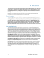
Standalone HDVR System
14
Hybrid Digital Video Recorder
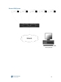
Remote HDVR System
15
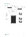
Multi Branch Office HDVR System
16
Hybrid Digital Video Recorder
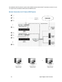
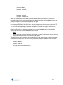
Enterprise HDVR System
17
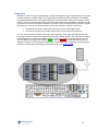
A detailed example of a small enterprise system is shown to illustrate network configurations which will
provide satisfactory performance for your HDVR systems. In the drawing below, it is assumed that the
customer has a pre-existing data network with servers that provide centralized file storage and/or
applications to client computers on the network. The HDVR client can be installed on as many of these
client computers as desired. The second Ethernet switch is only required if there are more network
client computers than ports on the first Ethernet switch.
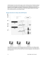
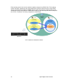
Network Connections for Analog Camera HDVR System
Gigabit Ethernet connections are recommended between the HDVR servers and the Ethernet switch,
and between Ethernet switches. While a 100 Mbps connection from the switch to each HDVR Client is
sufficient, it can be seen that each active HDVR Client increases the aggregate network bandwidth out
of the HDVR server.
18
Hybrid Digital Video Recorder
Network Bandwidth Example for Analog Camera HDVR System
19
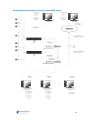
An installation with IP cameras is quite similar. HDVR recommends that the IP cameras are wired in “homerun” style back to an Ethernet switch near the HDVR Server.
Network Connections for IP Camera HDVR System
20
Hybrid Digital Video Recorder
Again, referring to the diagram below, gigabit Ethernet connections are recommended between the
HDVR servers and the Ethernet switches, but 100 Mbps connections from the switches to each IP
camera and HDVR Client are sufficient.
Network Bandwidth Example for IP Camera HDVR System
21
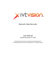
3. Chassis Layout
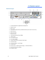
Back Panel Layout
1. 10/100/1000 Mbits/sec Gigabit Ethernet Adapter Port
2. Keyboard Input
3. Mouse Input
4. 4 High Speed USB 2.0 Ports (2 additional USB 2.0 ports on the front of the unit)
5. Audio Line Input
6. Audio Line Output
7. Microphone Input
8. 1 RS-485/RS-422 Serial Port (COM4)
9. 1 Relay Output
10. 8 TTL Output Triggers
11. 16 TTL Input Triggers
12. 1 Switched Multi-Picture Composite Video Output
13. 16 Camera Inputs
14. 16 Camera Outputs – Loop Through
15. 16 Audio Inputs
16. AC Power Input – Switching Power Supply – 115V/230V, 50/60 Hz
17. 9 Pin RS-232 Serial Port (COM1)
18. DVI Monitor Output
22
Hybrid Digital Video Recorder
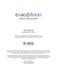
Front Panel Layout
1. 2 USB 2.0 ports (4 additional USB 2.0 ports on the back of the unit)
2. Power switch – turns power on/off the system
3. Reset Switch
4. Power LED
5. Hard Drive LED
6. Unused
23
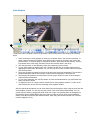
4. Hardware Installation
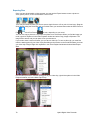
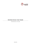
Basic Connections
Analog Camera
Audio Input
Analog Camera
Monitor
Power Cord
Ethernet
Switch
Keyboard
IP Camera
Mouse
1. Connect the mouse to the bottom USB port
2. Connect the keyboard to the top USB port
3. Connect the monitor to the DVI port
4. Connect the power cord to the back of the unit and a power source
5. Connect the cameras to the BNC connectors
6. Connect the audio to the RCA connectors
7. Connect the Ethernet switch to the 10/100/1000 Mbits/sec Gigabit Ethernet Adapter Port
8. Connect the IP camera to the Ethernet switch
24
Hybrid Digital Video Recorder
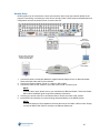
Network Setup
HDVR systems can be connected to a local area network (LAN) or wide area network (WAN) for the
purpose of monitoring or searching for video from a remote location. HDVR systems administration and
configuration can also be performed from a remote client PC.
Exploded
Section
Ethernet
Switch / Router
Remote Client Application
Monitor & Search Video
Remote Administration
Cable or
DSL Modem
Network
LAN/WAN
Internet
1. Connect the HDVR 10/100/1000 Mbits/sec Gigabit Ethernet Adapter Port to an Ethernet Switch /
Router with Cat5 cable and RJ-45 connectors.
2. Connect the Ethernet Switch / Router to a Cable or DSL modem.
3. Connect the Cable or DSL modem to your cable outlet or DSL connection port.
NOTE:
In the first three steps, please refer to your manufacturers Ethernet Switch / Router and Cable /
DSL modem installation guide for specific installation instructions.
4. Connect your remote client PC to an Ethernet Switch / Router and Cable / DSL modem.
5. Install HDVR client software for remote viewing and administration of the HDVR System.
NOTE:
Local Area Network (LAN) installations eliminate the need of the Cable or DSL modem. Simply
connect the HDVR and client PC directly to the Ethernet Switch port.
25
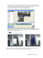
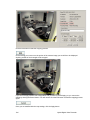
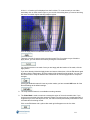
RS-422/RS485 Port Setup
The HDVR System has one RS-485/RS-422 serial port that can be configured to control a variety of
Pan Tilt Zoom (PTZ) cameras. The RS-485/RS-422 serial port terminal block plug on the back of the
HDVR unit can be removed to easily connect the cable that controls the PTZ camera. There are four
small screws on the top of the connector that need to be partially unscrewed in order to insert the wire
into the individual connections (Tx+, Tx-, Rx+, Rx-). Once the wires are inserted into the connector,
tighten each screw for a secure connection and then re-insert the connector in the back of the unit.
26
Hybrid Digital Video Recorder
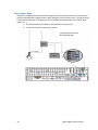
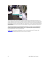
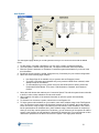
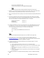
Trigger Input
HDVR has 16/32 TTL trigger inputs that are configured through the Trigger Input Setup screen as either
normally opened or normally closed. The Trigger Inputs terminal block plug on the back of the HDVR
unit can be easily removed to connect the wires from the source sensor device (in this example a door
sensor). There are small screws on the top of the connector that need to be partially unscrewed in order
to insert the wire into the individual connections. Once the wires are inserted into the connector, tighten
each screw for a secure connection and then re-insert the connector in the back of the unit.
1. Connect the one source output sensor wire to any of the 16/32 trigger inputs.
2. Connect the second source output sensor wire to one of the ground connectors.
You can verify the proper operation of the input state by going to the Trigger Input setup screen and
observing the “Status” state, which toggles back and forth between “Normal” and “Alarmed”. By default
the “Normal State” is set to NC (Normally Closed). If you trip the sensor by opening the door you will
see the “Status” state toggle from a green ‘Normal” to a red “Alarmed” indicating an alarm has been
detected. The alarm can be linked to an action such as recording video or triggering a relay by going to
the Event Linking screen and configuring the desired action (see Event Linking).
27
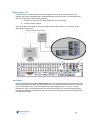
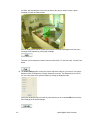
Alarm Output - Relay
HDVR has one Relay Alarm Output that can trigger a variety of external events. In this example, the
HDVR is integrated with a lighting control system through a 24 VDC latching relay. Through the Event
Linking screen HDVR can be configured to turn on the light upon predefined events (motion, input
trigger, etc…).
1. Connect the Alarm Output Relay to the transformers 24 VAC input
2. Connect the Common to the Relay Common
Controlling a branch circuit
with a latching relay
Relay
Line Voltage
Transformer
24 VAC
28
Hybrid Digital Video Recorder
Alarm Output - TTL
HDVR has 8/16 TTL Alarm Outputs that can be triggered by a variety of external events. In this
example, the HDVR is integrated with a building automation system through a 0-5 VDC Digital Input
Module for equipment or alarm status monitoring.
1. Connect any of the 8/16 TTL Alarm Outputs to the 0-5 VDC input
2. Connect ground to ground
You can set the “Normal State” of the Alarm Output to either High (5 VDC) or Low (0 VDC) on the
Alarm Output setup screen.
Building Automation / Control System
Status
Monitoring
Audio Input
HDVR systems have multi-channel Audio Inputs that can be configured to record audio from line level
security microphones and other line level audio devices. The audio connections receive an unbalanced,
line-level audio signal only. Line-level signaling requires a voltage between -1 V and +1 V into an
impedance of 1 kΩ or more. Microphones such as the Crown PZM11LL or Louroe Electronics ASK-4
KIT #101 pre-amplify the microphone signal and produce a line level output that is connected directly to
the HDVR audio inputs.
29
5. Software Operation
HDVR Software Overview
HDVR software is based on a client/server architecture. Client/server architecture provides a scalable
platform, whereby each computer on a network is a client, server or both a client/server simultaneously.
Client - A client is a computer system that accesses a (remote) service on another computer by a
TCP/IP network. HDVR Client software views and searches live and recorded video, audio and alarms,
and administers the HDVR Server configurations.
Server - A server is a computer system that provides services to other computing systems—called
clients—over a TCP/IP network. HDVR Server software records and retrieves video, audio and alarm
data and provides it to the HDVR Clients upon request.
Client/Server - A client and server can simultaneously reside and operate on one computer and
communicate to each other through a TCP/IP loop back interface. A loopback address is a special IP
address (127.0.0.1) that is designed for the client and server software to communicate with each other
on the same computer. By combining the functionality of HDVR Client/Server software on one system,
administrators can deploy both flexible standalone and network configurations that can scale to their
requirements.
There is one HDVR Client application that can be installed in two different configurations depending on
your requirements. The Client has the same features, functions and user interface in either installation
configuration. The first client installation is referred to as a Local Client, meaning the client resides on
the same system that is “local” to the server. The second installation is referred to as a Remote Client,
meaning it is installed on a different computer that is “remote” from the server. All interaction (viewing
live or recorded video and administration) with the server is performed through either the local or
remote client.
The Local Client is factory installed on the HDVR and the Remote Client is installed by a user on a PC
of their choice, either from the supplied CD or by downloading from the HDVR website
(http://www.americandynamics.net/).
HDVR software can be installed and operated in the following configurations:
1. HDVR Local Client and Server software is factory installed on the HDVR system. The HDVR
can either operate as a standalone system (not connected to a network) with the locally
attached VGA monitor, keyboard, mouse and cameras (analog and IP) or it can be connected
to a network to access other HDVRs.
2. HDVR Remote Client is shipped on a CD with the HDVR and can be installed on a PC of your
choice that is networked to the HDVR.
NOTE:
Please skip to the “Starting the Local Client” section, as the steps below pertain to the operating
system configuration on systems built at the factory.
Starting the HDVR System
The HDVR has been designed to be very easy to install, operate, and update. The system ships with
default settings that make it very simple to begin recording and searching video. Simply connect your
keyboard, mouse, VGA monitor and cameras. Turn on the power switch and the system begins
recording video from analog cameras. IP cameras require some steps to connect and configure.
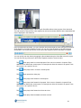
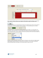
Logging In
Your HDVR System has been configured to take advantage of operating system security features. The
factory configuration includes two operating system accounts:
30
Hybrid Digital Video Recorder
1. Username: admin
Password: admin256
Privileges: computer administrator
2. Username: user
Password: user5710
Privileges: restricted user
When the computer boots, the HDVR Server automatically starts as a background service. The
operating system will then automatically log into the user account. Both user and admin accounts are
configured to start the HDVR Client immediately upon login.
Since it is running as a service, the HDVR Server will continue to record video even if no user is logged
in or running HDVR Client. The HDVR Server will only stop operating if the computer is shut down, its
service is stopped from the service control manager, or its process is stopped from the task manager.
To prevent this from happening inadvertently, the ability to shut down the computer or access the
operating system task manager has been restricted from the user account. To shut down the system or
perform maintenance, an operator must switch from user to the admin account via the operating
system start menu and enter the admin account password.
NOTE:
Default passwords should be changed by the operator and written and stored in a secure fashion to
prevent unauthorized access or modifications to the system.
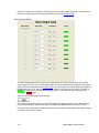
The HDVR Server can be accessed from multiple HDVR Clients, which may be running from the same
computer as the HDVR Server or from remotely networked computers. The HDVR Server has been
preconfigured with one user:
Username: admin
Password: admin256
Privileges: HDVR Server administrator
31
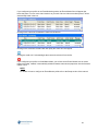
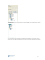
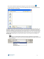
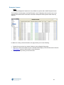
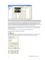
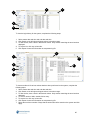
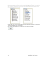
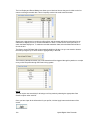
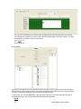
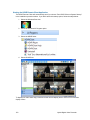
Each operating system user account maintains separate settings for its HDVR Client. These settings
include usernames, passwords, and network addresses required for HDVR Clients to access HDVR
Servers. By default both the user and admin operating system accounts have settings which provide
administrator access to the instance of HDVR Server running on the local computer, which is always via
the 127.0.0.1 IP address. The factory configuration is shown below:
32
Hybrid Digital Video Recorder
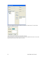
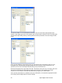
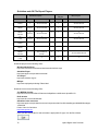
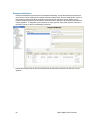
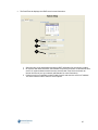
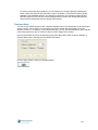
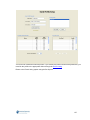
As part of the initial HDVR System configuration, HDVR recommends that the operator configure a new
user on the HDVR Server with restricted privilege level, and change the HDVR Client settings in the
user operating system account to connect to the local HDVR Server via this user. The new
recommended configuration is shown below. See the Users Setup section of this manual or the context
sensitive online help file for instructions on creating a new HDVR user.
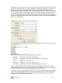
In the recommended configuration, a restart of the HDVR system due to power outage will put the
system in a safe state from which administrator privilege access to HDVR Server is not available
without knowledge of the operating system admin account password or the HDVR Server admin
password.
33
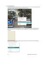
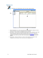
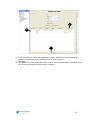
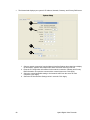
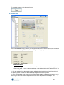
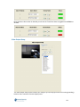
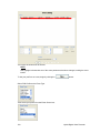
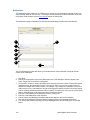
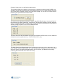
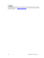
Starting the Local Client
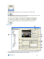
After successfully logging in, the local HDVR Client application will appear.
At the right end of the toolbar, you will find the Help button. Click it, to access online help for your HDVR
System.
You can also toggle to and from the online help system by using the F1 key.
34
Hybrid Digital Video Recorder
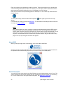
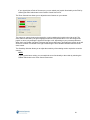
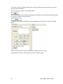
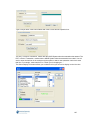
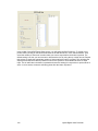
Operating Modes
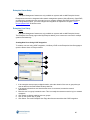
HDVR systems have three main modes of operation depicted by the three icons below:
Live Mode allows users the ability to view live video.
Search Mode allows users the ability to search for recorded video.
Setup Mode allows Administrators and Power Users the ability to configure systems.
Clicking on any of these icons will change the mode of operation.
35
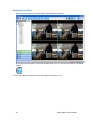
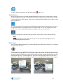
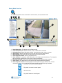
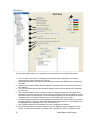
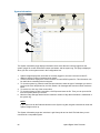
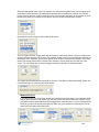
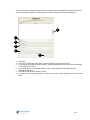
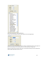
Live Mode Overview
Live Mode allows users the ability to view live video. To view live video on your HDVR System, you
must first click the Live Operating Mode button.
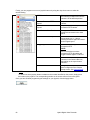
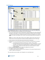
1. Operating Modes – displays the three available views, Live, Search, and Setup.
2. Title bar – displays HDVR Local and Remote Client application title.
3. Layout Buttons – allows you to organize your camera views to fit your needs.
4. Site Tree – displays icons representing HDVR systems, cameras, PTZ cameras, alarms,
monitor & audio inputs. Also displays setup icons used to configure HDVR systems.
5. Navigation Panel – displays cameras and video in organized groups and views.
6. Video View Panel – displays video of cameras.
7. Message – displays system messages providing feedback and information about operating the
system.
8. Date and Time – displays the date and time.
9. About Box – provides information about the client software you are using.
10. Help Button – displays information from the User Manual specific to the screen you are viewing.
11. Show/Hide Navigation Tree Button – expands the display by hiding the Navigation Tree.
12. Full Screen Button – enlarges the display by hiding the title and task bars.
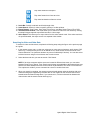
36
Hybrid Digital Video Recorder
13. PTZ Control Button – displays the PTZ Control window which allows you to maneuver a PTZ
camera.
14. Soft Trigger Icon – Displays the status of any soft triggers on connected HDVR servers.
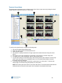
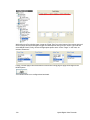
Layout Panel
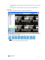
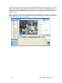
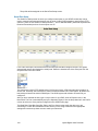
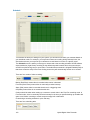
The system will default to the 2x2 layout, as shown in the example below.
You change the layout of the Video Panel by clicking on one of the Layout buttons. Once you select a
layout, it will become your new default.
NOTE:
Certain layouts are only available on widescreen monitors.
37
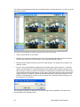
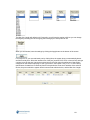
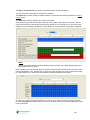
The system will automatically fill the Video View Panel with the cameras from your Live Site Tree in the
order they are listed.
There are several methods for adding cameras to your Video View Panel.
•
Select a Layout button on the Toolbar.
•
Double-click a camera name listed in the site tree. The system displays that camera in the upperleft video and fills the rest of the windows in order below that camera in the list.
•
Drag and drop a camera from the site tree into a video window. The window can be empty or full
when you do this.
•
Press F3 or the joystick button to display the Find Camera dialog, type the name of a connected
camera, and then click Find. This method allows you to display a camera without using a mouse.
When you type a sufficient number of characters to uniquely identify a camera name, the full name
of the camera will automatically appear; for this reason, this feature works best when cameras are
uniquely named. For example, if camera names start with numerical characters (such as 1-Front
Entrance, 2-Back Entrance, and so on), you can quickly find a camera by simply entering one or
two numbers in Find Camera.
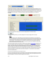
You can delete a camera from the Video View Panel by right clicking anywhere in the square and
selecting Disconnect Streaming Video.
38
Hybrid Digital Video Recorder
You can also access the Camera Setup screen directly from Live Mode by selecting Camera
Properties, and then clicking the OK button.
From here you can reconfigure the camera to fit your needs. See Setup for specific instructions.
39
NOTE: To view the video window panel in the largest area possible, press Alt and Enter simultaneously
on the keyboard. This combines the previously mentioned keyboard functions (F4 to hide the navigation
tree and F11 to hide the title and task bars) with the F8 function, which hides the message bar, the
date/time bar, and the toolbar. To reverse this mode and show all the hidden items, press Alt+Enter
again.
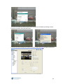
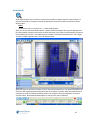
HDVR Replay
There may be instances when viewing live video feed that you want to replay a limited amount of
recorded video. This can be quickly accomplished by right clicking in the appropriate camera view and
selecting HDVR Replay. You will have the option of reviewing video in increments of 5 or 30 seconds or
1, 5, or 15 minute increments.
Once you select the desired video replay increment, the HDVR Replay window will open and begin
downloading the recorded video. A blue or green Scrub Bar will track the progress of the download. The
total number of frames in the video segment as well as the number that have been downloaded will also
be displayed in the status bar. If you wish to stop the download, click the Stop Download button at the
bottom of the window.
40
Hybrid Digital Video Recorder
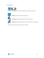
Once the download has started, you can scrub back and forth through the video using the Scrub Bar &
Scrub Handle or the seven Video Playback Controls at the bottom of the window:
Play video in reverse fast (double) speed
Play video in reverse in normal speed
Stop video play
Play video forward in normal speed
Play video forward in fast (double) speed
Play video forward one frame at a time
Play video backward one frame at a time
You can only scan the portion of the video that has downloaded. You will not have access to the entire
video segment until the download is complete.
You can also maximize, minimize, or close the Video Playback window by clicking the appropriate icon
in the upper-right corner.
See, Search Mode Overview for complete instructions on how to search video.
41
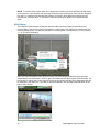
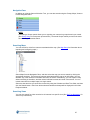
Live Event Monitoring
Event Monitoring is another feature that can be activated by right clicking in one of the video panels and
selecting Event Monitor and then the profile you would like to view.
At this point, an orange border will appear around the video panel and you will probably not have any
video in the panel until an event triggers. As motion is triggered on the cameras, it will trigger event
monitoring.
You can stop the Event Monitoring display by right clicking in the active video panel and disabling the
active event monitoring profile.
42
Hybrid Digital Video Recorder
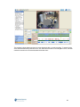
If you configured your profile as an Event Monitoring mode, the Event Monitor Box will appear just
below this panel. You can move it and resize it as you need. Once a video event takes place, it will be
automatically listed in the box.
Clicking on the event line will switch the video to that camera.
Clicking on the small blue rewind button will replay the event as it was tripped.
Clicking the small red ‘X’ acknowledges the event and removes it from the list.
If you configured your profile in Virtual Matrix Mode, you will not see an Event Monitor box as motion
triggers recording. Instead, it automatically switches between cameras and pops them into the frame as
motion occurs.
NOTE:
For details on how to configure an Event Monitor profile refer to the Setup section of the manual.
43
Event Buttons
Your HDVR system allows you to monitor live video from a remote location using a separate client
application. If you identify suspicious activity, you may want to send a notification via the server housed
at the location being monitored. This notification is called a Soft Trigger. For example, you can activate
an alarm, turn on a light, or trigger a door lock by using the Event Button feature on the client and the
Soft Trigger feature on the server.
The Soft Trigger feature is set up on the Event Linking screen in the Setup Mode. See Event Linking,
for detailed instructions.
Once you have set up a Soft Trigger, you will see the Soft Trigger icon in the toolbar at the top of the
Live Panel screen.
Simply click the icon to access the Soft Trigger window.
To activate any of the preset soft triggers, simply select the corresponding checkboxes.
Notice the status changes from Normal (green) to Alarm (red), indicating that the soft trigger has been
activated. To deactivate the soft trigger and return to a normal status, simply deselect the checkbox.
As an alternative to the Soft Triggers window, you can also create one or more, soft trigger shortcuts by
using the Event Button feature on the Client Setup screen in Setup Mode. See Client Setup, for detailed
instructions.
44
Hybrid Digital Video Recorder
Site Tree Navigation
Since you may not want to view your cameras in the order they appear in the Live Site Tree, your
HDVR System allows you to organize your cameras into Groups. (For instructions on creating camera
groups, go to Camera Setup.) This will enable you to efficiently view the cameras in the order you
choose regardless of how they are listed in the Live Site Tree. Once you setup the camera groups, you
need to select the cameras in those groups by clicking on the Group button in the Navigation Pane.
For example, if you want to view the Back Door, Front Desk, West Hall, and Reception Desk cameras
you would have to individually drag and drop these cameras in the Video View Panel because they are
not listed in order in the Site Tree. Using the Live Groups navigation, you can double click on the first
camera in the Perimeter Group and the other cameras in that group will be displayed in the Video View
Panel in the order they are listed.
You can also organize your cameras into preset Views.
There are several methods for creating a View. The simplest method is to select a Layout button in the
Live mode and drag the cameras, audio, and/or POS data you want to the appropriate spot on the
Video View Panel. Once you have everything laid out the way you want it, click the Save View button at
the top of the Live Site Tree.
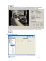
45
This will take you to the HDVR Views window.
Type a unique name for your view in the View Name field. The system and camera names will be
displayed when you hover over the view name in the Live View Site Tree.
46
Hybrid Digital Video Recorder
You can also include a description that will be added to the top line of the View tooltip, by typing it in the
Description field.
Once you have typed a unique name and a description if desired, click the Apply button.
Once you have saved your view, you can access it by clicking the View button from the Navigation
Pane. Select your view from the Live Views Site Tree and the camera layout you saved will be
recreated in the Video View Panel.
You can also modify your views by clicking the Modify button at the top of the View Site Tree.
47
Here you can organize your views into folders or create tours of multiple views. To create a folder,
simply click the New Folder button.
Type a unique name for the folder and a description if desired.
The folder will appear in the My Views Site Tree in the lower-left quadrant of the screen. You can then
drag and drop any views you wish to place in the folder.
48
Hybrid Digital Video Recorder
You can then organize your folders within your views by dragging it to the desired location in the My
Views Site Tree.
If you would like your video view panel to automatically cycle through two or more views, you can
create a View Tour. Begin by clicking the New Tour button in the center of the Modify Views window.
49
You will see a New Tour icon at the bottom of the My Tours tree in the lower-right quadrant of the
window. In the upper-right corner of the window, type a unique name for the tour in the Tour Name field.
You can then begin adding views by selecting them from the My Views Site Tree and clicking the Add
button.
Once you have added all of the desired views, you may want to type a description of the tour in the
Description field. This description will appear whenever you hover your cursor over the tour. It is
optional, but it can serve as a helpful reminder when you go to select the tour.
Below the Description field, is the Dwell Time field. This sets the amount of time, in seconds, each view
will remain in the Video View Panel before cycling to the next view. In this example, we used 5
seconds. You can increase or decrease the dwell time by using the up or down arrows.
Once you have named the tour, added the views and a description, and selected the appropriate dwell
time, simply click the Apply button to save the settings.
50
Hybrid Digital Video Recorder
You can also organize your tours in folders by creating a new folder and then dragging and dropping
the appropriate tours in the folder.
You can now select the tour from the Live Views Site Tree and the views you have created will cycle
through the Video View Panel.
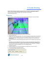
Live Maps
The Live Maps feature allows you to manage your cameras and devices using a graphical
representation of their physical location.
Live Maps allows you to select from a list of maps that you have imported into the HDVR. When you
select Maps from the navigation pane, all the maps that you have entered are listed, organized based
on parent and child maps.
You can display a map in the video view panel by double-clicking its name in the list or by dragging it
into a video window. The map can be displayed in 1x1 mode or with video from any combination of
cameras. A configuration with multiple windows displays video or data from as many devices
associated with the map as possible in the available video windows. Multiple maps can be displayed in
the same configuration.
51
Each map contains icons showing the location of devices. These icons change color to represent the
current recording status (blue for motion, for example). You can display video or data from the device
that it represents by double-clicking the icon or by dragging it to a video window.
Each map can contain icons representing parent or child maps. To view a child map, double-click the
following button:
To view a parent map, double-click the small map button
window.
in the upper-right corner of the map
For information on setting up maps, see Map Setup. For information on searching for video on devices
in a map, see Searching Maps.
NOTE:
Maps can be created on a client computer, but they are associated directly with all HDVR servers
that have cameras and devices associated with the map. Thus, any map that you create can be
seen by other users when they are connected to any server that the map is associated with. To see
which servers a map is associated with, right-click the map on the Live Maps page and select
Properties. All associated servers are listed in the properties window, and you can view the setup
page for the map by clicking the OK button that appears.
About HDVR
Moving to the upper-right corner of the title bar, you’ll see an About HDVR Box.
Clicking on this box provides information about the client software you are using. This information will
be important when troubleshooting any issues you may have using your HDVR System.
Online Help System
You can also access online help for your HDVR System by clicking the Help button or the F1 key. The
system will default to information regarding the topic matching the part of the system you are working
in. For more instructions on using the Online Help system, see Starting the Local Client.
52
Hybrid Digital Video Recorder
To exit the Online Help system, click the Close button
or the F1 key.
Display Buttons
Next to the Help button, you’ll find the Hide/Show Navigation Panel button. Click the button to enlarge
the HDVR display by hiding the Live Camera Site Tree. Click it again to return to the normal view. The
F4 key will perform the same function. Click it once to enlarge the HDVR display. Click it again to return
to the normal view.
The Full Screen Mode button enlarges the HDVR display by hiding the title and task bars. Click it once
to expand the display. Click it again to return to the normal view. The F11 key will perform the same
function. Click it once to expand the display. Click it again to return to the normal view.
The F8 key will expand the display by hiding the toolbar. Click it again to return to the normal view.
NOTE:
To expand your display to the maximum size, you can use all of the panel navigation and/or
corresponding function keys at once.
PTZ Control
The PTZ Control Button displays the PTZ Control window which allows you to maneuver a PTZ camera
or digitally zoom any video.
Click the button to access the PTZ Control windows. Please note that the controls will only open when a
PTZ enabled camera is displayed in the Video View Panel. Even if you do not have a PTZ camera, you
can use the digital PTZ feature to zoom in and pan around an image, provided digital PTZ has not been
disallowed during Setup. To enable digital PTZ, right click in the appropriate Video Panel and select
Digital PTZ. A checkmark will be displayed in the menu once the digital PTZ feature has been enabled.
53
Once you open the PTZ Control windows, a green border will be displayed around the Video Panel in
use. The name of the camera being controlled will also be displayed in the PTZ Control title bar. To
switch the controls, click anywhere in the desired video panel.
You can also click and drag on the title bar of the PTZ Controls to move them anywhere on your
screen.
To control Pan/Tilt, click on the green arrow buttons. To control Zoom, click on the Out or In buttons.
To control the speed of the pan/tilt and zoom functions, adjust the Speed slider bar directly below each
feature.
When using cameras that support Focus and Iris, you can also control those features using the PTZ
Controls. You can focus Far or Near, or you can click Auto to activate auto-focus. Similarly, you can
increase the iris setting by clicking Open, reduce it by clicking Close, or activate auto-iris by clicking
Auto.
54
Hybrid Digital Video Recorder
You can also use the Preset buttons you have setup by clicking on the green, numerical buttons at the
bottom of the PTZ control. For directions on how to setup a Preset button, see Camera Setup. By rolling
your cursor over the Preset buttons, you can access a tool tip based on the preset name you typed in
when you set up the PTZ camera.
An even more efficient way to access the PTZ Controls is to use the Arrows, Page Up, and Page Down
keys on your keyboard. The arrow keys will move your camera to the left, right, up, and down. Page Up
will zoom in, and Page Down will zoom out.
When you reach the edge of the image, PTZ limit indicator will be displayed.
To get a closer view, simply use your mouse roller to zoom in. The PTZ limit indicator will disappear,
allowing you to pan the image again.
Clicking Alt and Z at the same time will enable the zoom box. You can zoom in on a particular location
by holding down the control key and dragging the zoom box over the desired portion of the image.
Clicking Alt Z again will bring it back.
You can also use your mouse to access the PTZ presets by right clicking anywhere in the PTZ Video
Panel and selecting PTZ Presets and then the name of the desired preset.
55
You can also use your mouse to maneuver the PTZ controls within the PTZ Video Panel. Move your
cursor to the top and center of the PTZ camera view and you should see an up arrow. Click your mouse
and the camera will move up. Move your cursor to the corner of the box and you will get a diagonal box.
By clicking your mouse the camera will now move in that direction. You can continue this process along
the remaining sides and corners of the PTZ camera display until you have positioned the camera in the
desired location.
You can zoom the camera in and out by using your mouse roller. To zoom in, roll your mouse wheel
forward one click and then quickly roll it back one click. To zoom out, roll the mouse wheel back one
click first and then one click forward. Remember, you can adjust the speed of the Zoom feature by
using the Speed slider control on the PTZ Control.
Finally, if you have access to a USB joystick, you can use it to maneuver your PTZ controls. See
Joystick Setup, for detailed instructions on how to set up your joystick.
56
Hybrid Digital Video Recorder
Search Mode Overview
The Search page allows users to search for recorded video, events, and other data.
1
12
13
14
6
2
4
7
11
10
3
5
15
9
8
1.
2.
3.
4.
5.
6.
7.
Search Mode Icon. This button runs the Search mode.
Camera Selection Tree. Select cameras, audio, or data sources to search.
Navigation Pane. Display individual cameras, camera groups, maps, views, or events.
Search Range. Select a date and time for the start and end of the search period.
Search Button. Click Search to find video based on the search settings.
Video Playback Window. Video is played back here.
Video Timeline. To expand or shrink the timeline, click the plus and minus buttons. To change the
start or end time of the timeline, click the left or right arrow buttons.
8. Recorded Video Bar. These color-coded bars represent video that has been recorded.
9. Video Cursor. This shows where in the timeline the displayed video was captured.
10. Video Playback Controls. Standard playback controls (left from right): Reverse fast, reverse
normal speed, stop, play normal, play fast, stop download, step forward, step backward.
Play video in reverse fast (double) speed
Play video in reverse in normal speed
Stop video play
Play video forward in normal speed
57
Play video forward in fast speed
Play video forward one frame at a time
Play video backward one frame at a time
11.
12.
13.
14.
Scrub Bar. Quickly scrub back and forth through video.
Smart Search. Search for video in specific portions of a video window.
Export Buttons. Save Picture, Save Video, Print Picture, and Burn Saved Files to CD or DVD.
Thumbnail Search Mode. This mode allows you to search for video from one camera by viewing
thumbnail images captured at specified intervals in a time range.
15. Quick Export. This allows you to export video from the entire search result. If the entire result has
not yet downloaded, the export occurs in a separate video window.
Searching for Video and Other Data
To search for video and other data, complete the following steps using the figure on the previous page
as a guide:
1. In the camera, group, map, or view tree, select one or more sources (cameras, audio inputs, POS,
and so on). To search every source on an HDVR server, check the box next to the server in the
Camera Selection Tree (and then deselect any sources individually if desired). You can also select
individual sources using the check boxes next to each camera.
2. Select the date and time you want to search. Click Search.
NOTE: If the client computer and the server are located in different time zones, you can select
between Client Time or Server Time. Search result listings are applicable to the selected time zone,
and the time offset between the time zones is shown in parentheses. The Client Time and Server
Time options are visible if you are connected to a server in another time zone.
3. When your search is complete, the camera names selected appear under the timeline with colorcoded recording bars representing recorded data. A color legend for the recorded video bars is
located below the Search Range area; if you cannot see it, click the horizontal bar between the
video window and the search results and drag it up.
58
Hybrid Digital Video Recorder
Thumbnail Search Mode
Thumbnail search mode allows you to visually scan for video from a single camera by viewing thumbnail
images captured at specified intervals in a time range.
6
1
2
7
8
3
5
4
To perform a thumbnail search, complete the following steps:
1.
2.
3.
4.
5.
6.
7.
8.
Click the Thumbnail Search Mode button.
Select one camera from the camera selection tree.
Select a search range.
Click Search to display thumbnails of images captured at constant intervals during the search
period.
The capture time of each thumbnail is represented on the timeline by vertical orange lines.
To display more or fewer thumbnails, select a video window layout.
To play video starting at a thumbnail image, either double-click the video window or click the play
button under the image. If you immediately return to the Thumbnail Search Mode, the same
thumbnails should be displayed.
To decrease the search range, click a Zoom In (plus) button in a video panel. To increase the
search range, click a Zoom Out (minus) button in a video panel.
NOTE: Each video panel has a Zoom In and Zoom Out button. The thumbnail associated with the
selected button becomes the center point of the increased or decreased search range.
59
Video Timeline
Just above the Camera Selection List and the Recorded Video Bars, you’ll find the Video Time Line.
The system will automatically display a two-hour timeline in 30 minute increments.
You can adjust the search time by clicking the left or right arrows or by typing a new start time in the
Start Time field and clicking the Search button.
In addition to 30 minute increments (shown above), the Video Timeline can be displayed in increments
of five minutes (A), as well as one (B), two (C), or 24 hours (D).
A.
B.
C.
D.
You can adjust the time increments by using the Zoom buttons. Click the (-) button once to change the
display to shorter increments. Click the (+) button to display longer increments.
The yellow Video Cursor is used to select a segment of recorded video.
60
Hybrid Digital Video Recorder
Video Playback
7
4
2
1
6
3
5
To play back video, complete a search as described in the previous section and complete the following
steps:
1. Select a camera for video playback by clicking on a camera name in the search results area. To
select multiple cameras for playback, press and hold the Control key and then click each of the
camera names. To select a range of consecutive cameras, press and hold the Shift key, click the
first camera name in the range, and then click the final camera name in the range.
2. Click the play button to start displaying video at the beginning of the timeline.
3. To play video starting at another point on the timeline, double-click a recorded video bar in the
appropriate location under the timeline. Or, you can click once on the recorded video bar and then
click the Play button.
4. The green progress bar shows how much of the total video has been downloaded. The number of
frames downloaded and the total number of frames are also displayed in the status bar.
5. The background behind the recorded video bars turn gray to show how much of each camera’s
video has been downloaded.
6. To stop video download, click the Stop button. All video downloaded before you pressed the Stop
button can still be viewed.
7. To digitally zoom in on a single camera, double-click its video playback window. To return to the
multi-camera view, double-click the remaining video playback window.
After the download has started, you can scrub back and forth through the video using the scrub bar and
video playback controls. You can view only the portion of the video that has downloaded. You can
quickly scan the video by dragging the slider to the left or right or by pressing Enter or Backspace on
the keyboard. (Enter and Backspace play every frame of video as quickly as the system hardware
allows, unlike the normal Play and Reverse buttons, which play video at actual speed even if frames
must be skipped to do so.)
61
The video clip shown in the figure above was set up to record on motion and it has an alarm linked to
the front door opening. The blue border indicates that the recording occurred using the motion mode. A
red border around the playback window indicates an alarm triggered the recording.
To zoom in on a single camera, double click its Video Playback window.
To return to the multi camera view, double click the remaining Video Playback window.
In some cases, wind or some other invisible motion sets off the camera. On an analog camera, you can
highlight the motion that triggered the recording to identify the cause by right clicking anywhere in the
playback window and select View Motion.
NOTE:
This feature is not available on IP cameras.
Blue motion boxes will mark the area where the motion occurred. When you want to remove the motion
boxes, right click in the Video Playback window again and select Disable Motion.
62
Hybrid Digital Video Recorder
When the video playback begins, a blue or green Scrub Bar will track the progress of the download.
The total number of frames in the video segment as well as the number that have been downloaded will
also be displayed in the status bar.
Once the download has started, you can scrub back and forth through the video using the Scrub Bar &
Scrub Handle or the Video Playback Controls. You can only scan the portion of the video that has
downloaded. You will not have access to the entire video segment until the download is complete.
You can quickly scan the video by dragging the Scrub Handle along the Scrub Bar to the left or right.
You can also use any of the seven, blue Video Playback controls to scan the video.
The
button plays video in reverse fast speed. Click it once to reverse in 2x speed. Each
additional click doubles the current speed. For example two clicks will reverse in 4x speed. Three
will increase it to a speed of 8x, etc.
The
button plays video in reverse in normal speed.
The
button pauses the video play.
The
button plays video forward in normal speed.
The
button plays video forward in fast speed. Click it once to forward in 2x speed. Each
additional click doubles the current speed. For example two clicks will forward in 4x speed. Three
will increase it to a speed of 8x, etc.
The
button plays video forward one frame at a time.
The
button plays video backward one frame at a time.
63
Another way to quickly scrub through video is by pressing Enter or Backspace on the keyboard. To do this,
select a video window and then hold down the Enter button to scrub forward or the Backspace button to
scrub backward. Enter and Backspace play every frame of video as quickly as the system hardware allows,
unlike the normal Play and Reverse buttons, which play video at actual speed even if frames must be
skipped to do so.
When you play back video associated with POS data, any associated video is displayed in sync with the
POS overlay data, as shown in the following figure. Notice the data displayed on the right for the transaction
that was just completed in the video window.
64
Hybrid Digital Video Recorder
Smart Search
Smart Search allows you to search for occurrences of motion in specific areas of a video window. To
activate Smart Search, complete a search as described in the previous section and click the Smart
Search button:
NOTE:
Smart Search can be run only on a 1 x 1 video window layout.
When you click on the Smart Search button, a Smart Search box appears and a grid is displayed over
the video window. Use the mouse cursor to select grid boxes in the region of interest where you want to
view all instances of motion. The selected boxes are filled in with blue; to deselect a box, click it again.
To select multiple adjacent boxes, click and drag the cursor.
When the region of interest is complete, click OK in the Smart Search box. The system searches for all
video from the original search that contains motion in the region of interest. When the Smart Search is
complete, the number of frames containing motion in the region of interest is displayed. Click OK to
view the frames. Smart Search frames appear in orange in the video results bar:
65
When orange bars appear in the video results bar, only the Smart Search frames that they represent
are played back in the video playback window; any non-Smart Search frames in that time range are
skipped.
66
Hybrid Digital Video Recorder
Navigation Pane
In addition to using the Camera Selection Tree, you can also search using the Groups, Maps, Views or
Events Navigation Pane.
NOTE:
Conducting a Groups search allows you to organize your cameras in groups that suit your needs.
(See Group Setup for Groups set up instructions.) The actual Groups search process is the same
as conducting a Cameras search.
Searching Maps
You can search for video from cameras associated with a map. (See Map Setup for information about
importing and configuring maps.)
Select Maps from the Navigation Pane, and then select the map you want to search by clicking the
appropriate checkbox. This selects all cameras associated with the map or its child maps. You can
deselect any of the cameras to eliminate them from the search. Alternatively, you can expand a map
without selecting its checkbox, and then select individual cameras to include in the search. You can
include cameras from multiple maps in a single search.
Select the date and time you would like to search by using the Calendar and Start Time fields, and then
click the Search button. Video from all the selected cameras and maps will be displayed in the Video
Playback window.
Searching Views
You can also search for video recorded on all cameras in a specific view (See Site Tree Navigation, for
View set up instructions.)
67
Select Views from the Navigation Pane, and then select the View you want to search by clicking the
appropriate checkbox. Select the date and time you would like to search by using the calendar and
Start Time field, and then click the Search button. All of the cameras in the View are then displayed in
the Video Playback window.
To zoom in on a single camera from the view, double click on the video in the Video Playback window.
To return to the multi camera view, double click in the Video Playback window again.
Searching Events
If you want to narrow your search to a specific event previously configured in Event Linking instead of
all recorded video, select Events from the Navigation Pane. You can search for the event to locate
associated video or audio. To do this, click the Events button on the Navigation pane and the Event you
want to search. Then Select the desired date and time and click the Search button.
See Event Linking for instructions on creating and linking an event.
68
Hybrid Digital Video Recorder
The red bars indicate instances when the event triggered video or audio recording. To search for the
video associated with this particular event, click the Cameras button in the Navigation Pane, and then
conduct a search on the camera associated with that event.
69
Exporting Files
Once you have downloaded a video segment, you can use the Export buttons to save a picture or
video, print a picture, or burn saved files to a CD or DVD.
There may be instances when you want to save a single frame to a file or print it in hard copy. Drag the
Scrub Handle along the Scrub Bar until you find the frame you need and then select the Save Picture to
File
or the Print Picture
or both, depending on your need.
You can also copy a picture to a clip board and paste it into a document. When you find the image you
need, right click anywhere in the Video Playback window and select Copy Image to Clipboard. The
image will be stored, and you can paste it into your document.
If you need to save a series of frames, you can save a video clip. To save a video clip, you must first
mark the starting point of your video clip by Scrubbing to the location on the Scrub Bar where you want
your video clip to begin. Right click anywhere in the Video Playback window and select Mark Export
Start.
Use the same process to mark the ending point of your video clip, right click anywhere in the Video
Playback window, and select Mark Export Stop.
70
Hybrid Digital Video Recorder
Once you have marked the beginning and ending points, click the Save Video Button.
You will be prompted to save the file. You can store multiple video clips in a directory and then email
the files or burn them to a CD or DVD.
The default directory is HDVR Files in My Documents. The file name will default to the camera name. You
can assign it a unique name or keep it as is. After you have named the file, select a file type. The system
defaults to a standalone *.exe file, which plays on its own and can be run by a Windows user who does not
have access to an HDVR Client. Alternatively, you can save the clip as a *.ps, *.avi, or *.mov file if you are
emailing it to another HDVR Client user; this will reduce the size of the clip. If you are running the client on
a Linux or Mac operating system, you should save the clip as a *.ps file unless you are emailing it to a
Windows user.
NOTE:
See the chart on the following page for information about file compatibility on each operating
system. Also, an *.exe file can be created using any operating system even though it can be viewed
using only Windows.
71
Quicktime and AVI File Export Players
Linux
Players
Windows Players
Video format
WMP*
Quicktime Player
VLC
MPlayer
Mac Players
VLC
Quicktime Player
AVI
MJPEG
●
●
with DivX decoder
●
●
●
●
with DivX decoder
AVI
MPEG4
●
with DivX
●
with DivX decoder
●
●
●
●
with DivX decoder
AVI
MPEG4
with ASP
●
with DivX
●
with DivX decoder
●
●
●
●
with DivX decoder
AVI
H.264
●
with DivX
●
with DivX decoder
●
●
●
●
with DivX decoder
Quicktime
MJPEG
●
●
●
●
●
Quicktime
MPEG4
●
●
●
●
●
Quicktime
MPEG4
with ASP
●
with 3ivx MPEG4
decoder
●
●
●
●
with 3ivx MPEG4 decoder
Quicktime
H.264
●
●
●
●
●
*WMP = Windows Media Player
Download players at the following URLs:
Windows Media Player
http://www.microsoft.com/windows/windowsmedia/default.mspx
Quicktime Player
http://www.apple.com/quicktime/download/
VLC Player
http://www.videolan.org/vlc
MPlayer
http://www.mplayerhq.hu/design7/dload.html
Download codecs at the following URLs:
3ivx MPEG4 decoder
http://store.3ivx.com/3ivxStore/?features=dec&platform=win&license=plus&Go=Go
DivX decoder
http://www.divx.com/en/downloads
Quicktime codec resources
http://www.apple.com/quicktime/resources/components.html?os=Windows&ctype=696d6463&csubtype
=48323634
Perian Codec for Quicktime
http://www.perian.org
Once you have named the file and selected the appropriate file type, click the Save button.
72
Hybrid Digital Video Recorder
To save data to a CD or DVD, insert a writable CD or DVD and click the “Save to a CD or DVD” button
at the top of the toolbar to display the Burn Disc window.
NOTE:
If you do not have a CD burner, the Save to a CD or DVD button will not be enabled.
Once you click the Save to a CD or DVD button, the Burn Disc window will be displayed.
1. You can change the name of the disc by clicking the Edit Disc Name button.
2. The Disc Contents list displays all of the video clips in your directory. Select the clips you want to
burn.
3. To review a video clip, select the file and click Open File.
4. The Disc Info box displays important information about your disc capacity. The first number listed
(MB) is the amount of space required to burn all of the video clips you have selected. The next
number represents the capacity of the disc you have inserted; if you forget to insert a disc, this
number is zero. If you insert or replace a disc, click Refresh Disc to update the numbers.
5. Click Burn Disc to open the Disc Burning Progress window. Review the Burn Options before
proceeding.
6. Click the Burn button to start the writing process. This may take several minutes, depending upon
the amount of video to be written.
73
S Mode Overview
Setup Mode is where Administrators and Power Users configure systems.
1. Setup Configuration Tree – click on any of the icons in the camera tree to take you to a new
screen (see number 3 below) for configuring the item you selected
2. My Systems – is the first screen that displays systems that you have connected to. If you have
only one stand alone system you will see one system listed on this screen. If you have
configured multiple systems with the Network Setup screen (see Add System) that you are
connected to you will see you will see each of those systems, the system status and the IP
address.
3. Setup Screen – this area is known as a “screen.” It’s the area that will change to a new
configuration screen when you click on the icons in the configuration tree.
74
Hybrid Digital Video Recorder
Add System
3
4
5
8
1
2
6
7
9
The Add System page allows you to add systems so that you can connect to them with the HDVR
Client.
1. To add system, click New. (Alternatively, you can “find” a system, as discussed below.)
2. The new system is added to the System List. The System Information fields are enabled.
3. Enter the system’s hostname or IP address. Contact the system administrator if you do not know
this information.
4. By default, the port number is 22609; change this only if necessary for your network configuration.
5. Select one of the following login methods:
•
•
•
Use Single Sign-On is available only on systems with an Enterprise license.
To require a username and password entry every time the HDVR Client is started, select
Always Prompt for Credentials.
To automatically log in to the system every time the HDVR Client is started, select Use
Credentials Entered Below. Then enter a valid Username, Password, and Password
Confirm.
6. Select the radio button that matches your Connection Speed. This tells the system how much audio
to buffer in order to help maintain a smooth audio stream.
7. When finished, click Apply. If the entered information is valid, the system is automatically
connected.
8. To disconnect or reconnect a system, select its box in the System List.
9. To find a system and its address on your network, enter the IP address range in the Find Systems
area. The first three boxes must be the first three elements of the IP address; the fourth and fifth
boxes are used to create a range of numbers for the final element of the IP address. Click Find to
list all systems whose IP addresses are in the IP address range. When the search is complete (or
when you click Stop, which replaces the Find button), you can select any of the systems to add the
system to the System List and populate the Hostname/IP Address field. You must still enter a valid
username or password to be able to connect to the system. Click Apply when finished.
75
Connected systems in the System List also appear in the Configuration, Live, and Search trees.
Disconnected systems do not appear in the trees.
My Systems
The My Systems page lists all added systems, along with their serial number, IP address/hostname,
connection status, license type, MAC address, subscription information, version information, status
(such as, Normal, Alarm, or Motion), and days of recorded video.
NOTE:
To display or remove a column on the My Systems page, right-click any column header and select
the column from the pop-up menu.
The following actions can be performed on the My Systems page:
76
•
To connect to or disconnect a system, right-click its connection status and select a Connect
option or Disconnect from the pop-up menu. To connect to or disconnect multiple consecutive
systems simultaneously, click on the connection status for the first system, and then press Shift
while you drag the cursor up or down (and then right-click).
•
To view the System Information page for a system, double-click the information listed in any
column for that system.
•
To view model number and serial number information for a system, right-click the system
name.
•
To view a MAC address and license key for a system and copy it to the clipboard, right-click its
information in the License, MAC Address, or Subscription column for that system and select
Copy to Clipboard (select the right arrow if necessary to see that option). You can then paste
the information into an email or other applications.
•
To update a license key for a system, right-click its information in the License column, select
Update, and select one of the options. If you select Update the License from File, you can
browse to a .KEY file that contains license information and click Open. If you select Update the
License from Text, you can type the license key manually and click OK.
Hybrid Digital Video Recorder
NOTE:
Alternatively, you can click Import Licenses at the bottom of the screen to enter multiple licenses
from a .CSV file, or click Export Licenses to compile all listed licenses into a .CSV file to import into
another client.
•
To view additional version information for a system, right-click the information in the Version
column for that system.
•
To view additional information about Alarm or Motion status, hover the mouse pointer over the
word while it appears in the Status column.
NOTE:
If the physical connection between the client computer and server is interrupted while you are
connected to the server in HDVR Client, the Connection Status will be displayed as Network
Activity Timeout. The status will then be displayed as Disconnected after a specific amount of time
that varies among operating systems
77
Client Setup
9
1
2
3
4
5
6
7
8
The Client Setup page allows you to customize your client based on your personal preferences.
1. The Live Video Panel section controls the colored borders that are displayed in Live mode to
indicate motion or alarm recording or PTZ focus.
2. Keep Aspect Ratio During Resize maintains video aspect ratios when HDVR Client is made larger
or smaller.
3. Restore Client on User Attention Request displays a minimized client if an event occurs requiring
user attention.
4. The VGA Acceleration Mode (Video Graphics Adapter) section resolves display issues caused by
the video card.
5. The Timelapse Playback section controls the amount of display time between video gaps due to
time-lapse recording or discontinuous motion. Normally, the system automatically jumps to the next
video frame after a one-second gap. You can decrease the dwell time to zero by sliding the interval
control to the left or increase the dwell time up to 15 seconds by sliding it to the right.
6. The Show Configuration Mode to Operating System Restricted Users checkbox allows you to hide
the Setup button for a client who has a restricted Windows setting. Only the Live and Search icons
are displayed to these restricted users if you select this option.
7. Select Disable Windows Font Smoothing if fonts are not appearing as desired.
8. Event Buttons allows you to create a shortcut to any Soft Triggers you have configured in Event
Linking. To create an Event Button, click New. Enter a description in the Tool Tip field and click
78
Hybrid Digital Video Recorder
Change Icon… . Select a default or custom icon and click Open. Select the Soft Trigger from the list
provided and then click Apply. The icons will be displayed next to the Soft Trigger icon on the Live
mode toolbar. You must select a different icon for each Soft Trigger shortcut.
9. The Colors section controls the default border colors for Motion, Alarm, Free Run, PTZ Focus, and
Event Monitor. To change a color, click on the colored bar of the border type, select a basic color or
create a custom color, and then click OK.
79
Joystick Setup
The Joystick Setup screen allows you to configure any standard USB joystick to work with your HDVR
system.
If you have more than one joystick plugged into your USB ports, you will need to select the joystick you
would like to configure in the Preferred Joystick field.
If the position control is drifting while the joystick is in its resting position, you can calibrate your joystick
by clicking the Calibrate button.
There are several Position Controls that can be adjusted to suit your personal preferences. The
sensitivity of the joystick can be adjusted by moving the Sensitivity slide bar to the left, making it less
sensitive, or to the right, making it more sensitive.
You can also alter the north and south movement of the camera or view. When the Invert Y Axis
checkbox is selected, the PTZ camera or digital PTZ view, represented by the red dot in the picture
above, will move north when you move your joystick down and South when you move it up. This can be
reversed by deselecting the Invert Y Axis checkbox.
NOTE:
80
Hybrid Digital Video Recorder
If your joystick has a Point of View source, you can switch your joystick functionality to the POV by
selecting the POV radio button in the Position Control Source box.
The Zoom Controls box allows you to adjust the zoom features on your camera.
The camera or camera view can be zoomed in or out by twisting the joystick to the right or left. The
zoom status is reflected by the green highlight as shown in the picture above. You can configure the
joystick to zoom in by twisting the joystick to the right or left, depending on your personal preference.
When the Invert Rudder checkbox is selected, the camera will zoom in by twisting the joystick to the left
and zoom out when it is twisted to the right. Deselecting the Invert Rudder checkbox will reverse the
zoom control.
The Sensitivity slide bar allows you to adjust the sensitivity of the twisting motion required to zoom the
camera.
NOTE:
If your joystick has a rudder, you can switch the zoom functionality to the rudder by selecting the
Rudder radio button in the Zoom Control Source box.
81
Finally, you can program one or more joystick buttons by using the drop down menu to select the
desired setting.
PTZ Zoom In/Out
Zooms the camera in and out. Click
the button(s) multiple times until the
camera is in the desired position.
Increase/Decrease PTZ Zoom
Speed
Adjusts the zoom speed of the
camera.
Increase/Decrease PTZ Pan/Tilt
Speed
Adjusts the pan and tilt speed of a
mechanical PTZ camera.
Next/Previous Video Panel
Changes the PTZ focus to the
next/previous camera in the video
panel.
View This Camera Only
Switches a camera in a multi-camera
layout panel to a 1 x 1 layout.
Clicking the button again will return it
to the original layout.
Toggle Digital PTZ
Switches between digital and
mechanical PTZ.
NOTE:
If the camera does not have
mechanical PTZ, this setting will
toggle between digital PTZ and off.
Traverse The Camera Tree
Moves to the next camera or set of
cameras in the Camera Site tree,
depending on the Layout button
selected.
Go to PTZ Preset Number 1-16
Navigates the PTZ presets that have
been configured on the Camera
Setup screen. See Camera Setup.
NOTE:
To determine which joystick button correlates to the number identified on the screen, simply press
the button on the joystick. The corresponding number on the screen will turn from red to green.
Once you have finished programming the settings for your joystick, click the Apply button.
82
Hybrid Digital Video Recorder
Enterprise Cameras
NOTE:
Enterprise Management features are only available on systems with a valid Enterprise license.
The Enterprise Cameras page under My Enterprise in the Configuration site tree allows you to see
expanded information about all cameras connected to Enterprise HDVR systems listed under My
Systems.
In addition to viewing camera information, this page allows you to do the following:
•
•
•
Double-click any column in a camera’s listing to view its Camera Setup page.
Right-click in the Record Status column to activate HDVR Replay on the selected camera. See the
HDVR Replay section of this manual for more information.
Sort any column by clicking on the column title.
83
Enterprise Notifications
Enterprise Notifications work the same as standard Notifications, except that notification profiles and
email servers can be configured on multiple systems simultaneously. See the “Notifications” section of
this manual for information about configuring message profiles and email servers. When you are
finished configuring the profiles and servers, select a profile to display the list of HDVR Systems that it
can be applied to. To associate a profile with one or more systems, select each system’s checkbox in
the Select column on the E-mail Message Profiles tab.
Repeat the same process on the E-mail Servers tab to associate an email server with one or more
systems.
84
Hybrid Digital Video Recorder
Enterprise Server Setup
NOTE:
Enterprise Management features are only available on systems with a valid Enterprise license.
Enterprise servers can be integrated with network management systems (Active Directory, OpenLDAP,
or Kerberos) to synchronize user accounts from your computer network and HDVR servers. Before
proceeding with this option, you must configure the integration as explained in Chapter 7 Active
Directory/OpenLDAP of this document.
Enterprise User Setup
NOTE:
Enterprise Management features are only available on systems with a valid Enterprise license.
The Enterprise User Setup page under My Enterprise allows you to create user accounts for multiple
systems simultaneously.
Creating New Users Using LDAP Integration
To create a new user using LDAP integration, click Query LDAP on the Enterprise User Setup page to
open the Select Users or Groups window.
1
3
2
4
5
6
1. If the enterprise servers span multiple domains, select the domain of the user or group that you
want to add from the Select Base DN drop-down list.
2. If the status indicator does not show that the server is connected, contact the network
administrator.
3. Enter the user’s or group’s network name. This is normally the username used to log in to network
computers.
4. Click Search to display matching users or groups.
5. Click on the correct user or group.
6. Click Select. The main Enterprise User Page then lists servers with active LDAP integration.
85
7
7. In the Select column, activate the checkboxes for servers that the user or group should have
access to.
Click Apply to save changes. On the Add System page, select Use Single Sign-on so that the HDVR
Client will pass the client computer’s login credentials to the server for validation when it starts. Failing
to select Single Sign-on could cause failed login attempts because of mismatched passwords.
NOTE:
Server entries with a red background have been configured for LDAP integration but are not
currently connected. If a server is not licensed as an enterprise system, NOT ENTERPRISE
appears in its Status column.
Creating New Users Without LDAP Integration
To create a new user without LDAP integration, complete the following steps.
1
2
5
3
4
1. Enter the username, password, and password confirmation.
2. Select a user group from the drop-down list.
3. Activate the Select All in Grid checkbox if the user account’s default setting should be applied to all
listed servers.
4. To see the actual passwords instead of asterisks, select the Show Passwords in Cleartext
checkbox.
5. Click Create New User to list the servers that the user can be added to.
86
Hybrid Digital Video Recorder
8
6
7
6. In the Select column, activate the checkboxes for servers that the user or group should have
access to. The user group can be changed for each server if required.
7. Click Apply.
8. The Status column displays the status of the selected account on each system. The status can be
OK, Pending, Not Enterprise, Disconnected, or Deleted.
87
Event Monitoring
The Event Monitoring screen allows you to set up your HDVR client to react to events that take place in
the server or servers to which it is connected.
To activate the Event Monitoring feature, you must first create and define a new Event Monitoring
Profile. A profile is a set of actions (e.g. the playing of live video or an alarm sound) triggered by
sources such as video motion, input triggers, etc. Each profile can then be activated and assigned to a
specific video panel by the user.
To create a new profile, click the New button in the Profiles field.
Give the profile a name and a description. In this example, we used Main Entrances. You can also type
a brief description of your profile in the Description field.
Next, you’ll need to select the type of profile you would like to create using the Type radio buttons.
88
Hybrid Digital Video Recorder
A Virtual Matrix profile will automatically show video as it is triggered. For example, if you have a series
of entrances in one profile, each time any of the entrances is triggered, the video panel will switch to the
camera displaying the most recent door motion.
Event Acknowledge Mode brings up a list of events which the user can click on to view giving you much
more control. Using the same Main Entrances profile as our example, instead of the video panel
automatically switching to the camera displaying the most recent door opening, the event would be
added to a list. You could then click on the item to display the video. This may be useful if a guard
needs to leave the monitor for a period of time. It is also helpful when you have events occurring on two
cameras at the same time. Instead of seeing each event for a split second, you can view each event for
as long as you need to.
Once you have initiated your profile, you need to add an event or events that you wish to monitor. If you
are familiar with HDVR’s Event Linking feature, this will look familiar to you.
Select an Event Type, and Event Source, an Action Type, and an Action Target. The options listed in
Event Source vary depending on which Event Type (such as triggers, serial ports, and serial profiles) is
selected and how it is configured. For more information, see the sections of Setup Mode Overview
related to the desired Event Type.
To add another event to this profile click on the other “New” button located at the bottom of the page.
Repeat this process to add additional events to the profile.
Click the “Apply” button on the upper right when you have finished your profile.
You can now view your event profile in Live mode. (Live Event Monitor)
Group Setup
The Group Setup screen is where you create logical groups of cameras from single or multiple HDVR
systems.
89
This is a useful feature when you have multiple systems with a fairly large number of cameras spread
across a large building or campus and you would like to place cameras in logically named groups such
st
nd
as 1 floor, 2 floor, and 3rd floor and so on. In this example you might have two HDVR systems with
16 cameras each, and you have a four story building that you want to place eight cameras on each
floor. Instead of viewing your cameras as they are physically connected to your HDVR systems, you
create four named groups consisting of eight cameras each. It’s much easier for a user to find cameras
when they are located in named groups that match the logical layout of their building.
In addition to monitoring live video, groups are very useful for searching video. On the search video
screen simply click on the Groups navigation pane on the lower left corner of the screen then select
your group and search.
To access the Group Setup page, click Group Setup from the Setup Site Tree.
Create a new group by clicking on the New button.
In the Group Details setup box Group Name will be populated with New Group. Type a unique name
over New Group and tab to the Description box to describe the new group you’re creating.
Select an icon to represent your group.
90
Hybrid Digital Video Recorder
This icon will be displayed to the left of the group in the Live and Search site trees.
To add cameras to your group, select a camera from the All Cameras list and then click the Add button.
The video will be displayed in the upper left hand corner, and your camera name will appear in the
Cameras in Group box. Continue adding cameras until your group is complete.
91
If you want to remove a camera from the Group, select the Camera from the Cameras in Group box,
and click the Remove button.
Once your group is complete, click the Apply button.
Should you decide you don’t want to finish setting up the group, you can click the Cancel button as long
as you haven’t clicked the Apply button yet.
To delete a group you have already set up, simply highlight it in the Groups list, and click the Delete
button.
Continue this process until all of your cameras are organized to fit your needs.
These groups can now be used to monitor live video or searching video.
92
Hybrid Digital Video Recorder
Map Setup
Maps allow you to organize your cameras and other devices using a graphics file.
To create a map from an existing graphic file, select Map Setup from the Navigation Pane. Click New
and then enter a Name and Description (optional) for the map. Click Choose Map to open the Map File
window, which allows you to browse for the graphic file that you want to use for the map (it is
recommended that you use a compressed graphic file, such as a PNG or JPEG, to improve
responsiveness). Select the file and click Open to display the map.
NOTE:
To create a child map for an existing map, select the existing map before you click New. This
allows you to place an icon representing the child map on the existing (or parent) map. Notice that
the child map is listed under the parent map when you click New.
The systems that you are currently connected to are listed in the Available Items section. Expand the
systems to display the devices associated with it. Any child maps that you create for this map are also
displayed in Available Items.
To add an icon representing a device or child map, drag the name of the device or map from the
Available Items section into the part of the map where the icon should be located. When you view this
map in Live Maps, double-clicking this icon will display video or data from the device or display the child
map.
To remove an icon from a map, right-click it and select Remove Selected Item. To flip the icon to point
the other way, right-click it and select Mirror Icon. To rotate the icon, right-click it, select Icon Rotation,
and select any of the available options. To change the appearance of the icon, right-click it, select Icon
Balloon, and select any of the available options.
NOTE:
If the map has a parent map, a small map icon representing the parent map is displayed in the
upper-right corner. You can drag this parent map icon anywhere on the map.
To complete a map, click Apply. To delete the map, click Delete
93
System Information
2
1
3
4
5
6
The System Information page displays information about users that are currently logged into the
system, plugin file version information number and status, and the system log. This page is displayed
when you click on the system name in the Configuration tree.
1. System Usage displays the users that are currently logged in, the user’s access level and IP
address, and the number of streams being viewed.
2. Version Information displays the version numbers for each HDVR system file. This information can
be useful when contacting technical support.
3. To view the system log, select the start and end date and, select the type of messages you want to
see from the Level drop-down list, and click Search. All messages that meet the search criteria are
listed.
4. To sort the list, click any of the column titles.
5. To view the system log with a text editor, click Export and save the file. Then you can open the file
from the location where you saved it.
6. Maximum Days Storage determines the maximum number of days that information is maintained in
the system log.
NOTE:
If you cannot see all the fields and buttons on the System Log tab, drag the horizontal bar under the
System Usage section up.
The System Information page also includes a Login History tab and an Audit Trail tab when you are
connected to a compatible system.
94
Hybrid Digital Video Recorder
4
3
1
2
5
To view the login history for the system, complete the following steps:
1. Select a start date and time and end date and time.
2. Click Search to list all login and logout actions in that time range.
3. To filter the list, enter a word in the Search column. Only actions containing the word are then
displayed.
4. To sort the list, click any column title.
5. Click Export to save the information as a separate log file.
5
1
3
2
4
6
7
To view an audit trail of various actions that have been performed on the system, complete the
following steps:
1. Select a start date and time and end date and time.
2. Click Search to list all login and logout actions in that time range.
3. To filter the list, enter a word in the Search column. Only actions containing the word are then
displayed.
4. To view an action in XML, double-click its entry.
5. To sort the list, click any column title.
6. Click Export to save the information as a separate log file.
7. Select the maximum number of days that the actions should be stored on the system and click
Apply.
95
System Setup
The System Setup page allows you to set basic system parameters for the client application. The page
is separated into the following three tabs:
•
The System tab allows you to create a name for the system, export and import settings from other
systems, import and export graphics, and manage the licensing of your system.
4
2
3
1
1. After configuring your system, it is recommended that you click Export Settings to export
system settings to a USB or network drive and store it off-site for recovery from a disaster
or malfunction.
2. If you ever need to restore the settings or simply import them from another system, click
Import Settings and apply the saved settings.
3. Unlicensed HDVR servers can connect to only one IP device at a time. To obtain your
license key online, provide the system MAC address to your dealer.
4. The dealer will contact American Dynamics to obtain the license, which is entered on the
System Setup page.
96
Hybrid Digital Video Recorder
•
The Date/Time tab displays the HDVR server’s time information.
1
2
3
1. Select the time zone and daylight saving time (DST) information for the server’s location.
2. On systems with Internet access, select Enable Time Server and enter a valid Internet time
server. On systems without Internet access, select Enable Time Server and enter an
internal time server (see your network administrator for more information).
3. If a time server is not available, select Enable Override and enter the server’s IP address.
This is the least accurate of the time server options.
97
•
The Network tab displays your system’s IP Address, Netmask, Gateway, and Primary DNS server.
1
2
3
4
1. Select a network connection from the Network Interface Settings drop-down list to display
its information. Systems with multiple NICs have more than one entry in the list.
2. Enter the IP Configuration information for the network connection. Gateway and Primary
DNS information is required to connect with a network time server. Click Apply.
3. Select the correct bandwidth setting to limit network traffic from the server to client
computers. Click Apply.
4. Select the IP Reconnection Settings value in seconds. Click Apply.
98
Hybrid Digital Video Recorder
Add IP Cameras
3
4
6
5
1
2
The IP Cameras page allows you to add IP cameras and devices to the system and configure their
settings. The following features are available on the IP Cameras page:
1. The Find IP Cameras section scans for supported IP cameras available on the same network that
the system is connected to. If you don’t see an IP camera that you expect to see on the network,
verify that the camera has been configured and that the camera can be pinged from a command
prompt. If you make any changes to an IP camera, click Rescan Network and check whether it is
listed.
NOTE: If you need to confirm which camera you are installing, right-click the camera in the IP
Camera List or Find IP Cameras list to access the camera’s website and view a video image.
2. Select a camera in the Find IP Cameras list to add it to the IP Camera List.
3. Alternatively, you can manually add a camera by clicking New and selecting the device type as
follows:
• If the appropriate manufacturer-specific driver is shown in the list, select it.
• Select the ONVIF driver (the level of integration can vary by manufacturer or model) if
you wish to communicate via the ONVIF standard, to an ONVIF compliant camera.
• RTSP-compliant cameras can stream video but not motion detection or camera
configuration data.
4. Enter a username, password, and IP address as configured on the camera.
5. Click Apply to save the camera configuration.
6. To enable a camera, select its checkbox in the IP Camera List. The number of cameras you can
enable is subject to licensing limits.
The camera will now also be listed in the Configuration, Live, and Search trees.
99
IP Camera Recording Setup
Once IP cameras have been added to the server you can enable recording, set the recording resolution
and recording frame rate measured in images per second (IPS). Each IP camera can be individually
set.
The Camera Recording Setup screen is where you enable cameras to record video, set the recording
resolution and set the image per second (IPS) recording rate.
The Camera Input column is the physical input connect that the camera is connected to on the back of
the HDVR. Refer to the Back Panel Layout.
If a camera has been connected to a HDVR system and the camera is producing a video signal, the
HDVR client application will automatically detect the video signal. If a video signal is detected it is
indicated with a green “YES” under the Video Detection column and by default the Record Enabled
column check box for that camera is checked. To disable recording uncheck the enable check box.
The HDVR systems by default are setup to record in CIF resolution if a video signal is detected.
You can change individual camera resolutions by clicking on the Record Resolution drop down box
and selecting one of the resolutions listed. Your options will vary based on the camera manufacturer
and model.
Once you have made the change you must click the Apply button to make the change.
100
Hybrid Digital Video Recorder
To cancel the changes, click the cancel button.
IP Camera Setup
The IP Camera Setup screen is where you configure the individual IP camera settings such as camera
name, on-screen display, PTZ settings, video settings, recording quality and motion and video masks.
IMPORTANT NOTE
Any camera settings that are not available in the HDVR software can be accessed through the
camera’s web page. To view a camera’s web page, click the hyperlink in the IP Address field. If you
don’t see a hyperlink beside the IP Address field, it could be for one of two reasons:
1.) You are not logged in to the operating system with administrative privileges. You will need to log in
to operating system account with administrative privileges to access the hyperlink.
2.) Your client computer is not located on the same IP subnet as the IP camera. This could occur if you
are using the client from a home computer to access a server at your office, for example. This
101
restriction should cause few issues because camera website settings are typically changed only during
initial configuration.
Most of the procedures for setting up an IP Camera are identical to those for an analog camera. See
Camera Setup, for instructions on adjusting all settings in the HDVR software with the exception of
Motion Mask, Motion Window, and Crop Window.
IMPORTANT NOTE
Some models of cameras allow you to create Motion Windows instead of Motion Masks. A Motion
Mask is an area of a video window where motion is ignored, whereas a Motion Window is an area
of a video window where motion is monitored.
This section discusses how to create a Motion Mask. However, a Motion Window can be created
using the same process.
To add a new Motion Mask or edit an existing mask, click the Edit button.
The Add and Remove buttons, as well as the Motion Mask tabs will now be enabled.
A separate tab will be created for each mask setting. To add a new mask, click the Add button.
Move your cursor to the video display panel at the top left corner of the IP Camera Setup screen.
Determine where you want to set your rectangular mask to appear, click in the upper-left corner and
drag it to the lower right corner. A blue rectangle will mark the location of the mask.
102
Hybrid Digital Video Recorder
If you are not happy with the location of the mask you created, you can delete it by clicking anywhere in
the mask area. You can also cancel any edits you have made on any of the Motion Mask tabs (as long
as you have not clicked the Apply button) by clicking the Cancel button.
The Sensitivity slider control increases and decreases the sensitivity of the motion necessary to trigger
the video recording. It is a useful tool for adjusting motion recording for certain environmental or camera
signal quality factors. For example, you can set the sensitivity high (90 or 100%) if your cameras
produce a good quality video signal with little noise and are in a bright environment because camera
noise or shadows won’t cause unwanted motion recording. If you have a dark environment with poor
visibility and a poor quality video signal, setting the sensitivity low (10 or 20%) will reduce unwanted
motion recording. The slider control ranges from 1% on the left being the least sensitive to 100% on the
right being the most sensitive. To adjust the motion sensitivity, you can move the slider to the right and
left or click on the control and use the left and right arrow keys.
The Percentage slider control increases or decreases the portion of the mask area that must be filled to
trigger video recording.
Once you get the Motion Mask in the location you desire, you can set the camera to record only when
motion occurs inside the mask area by clicking the Include button. This is the system default, but you
can also block recording in the mask area by clicking the Exclude button.
You can add additional Motion Mask tabs by clicking the Add button again and repeating the process
above. To set your Motion Mask tab or tabs, click the Apply button.
To remove a Motion Mask tab, click the Edit button, click on the tab you want to remove, and then click
the Remove button. You can also remove all of the Mask tabs by clicking the Edit button and then the
Clear button.
To return to the default settings, click the Defaults button. The system will reset the Format to H.264
and the Quality to 8. It will also clear any Motion Masks that had been created.
Some camera manufacturers have implemented cropping in their IP cameras. If you are using one of
those cameras, the Crop Window will be enabled, allowing you to crop unimportant portions of a
camera image in order to save disk space.
103
Click the Edit button to start the cropping process.
Click and drag your cursor over the portion of the camera image you would like to be displayed.
Anything outside of the rectangle will be cropped.
If you are not happy with the new configuration and you haven’t clicked Apply yet, you remove the
setting by clicking the Cancel button. You will need to click the Edit button to start the cropping process
again.
Once you are satisfied with the crop settings, click the Apply button.
104
Hybrid Digital Video Recorder
The camera display will lose video for a couple of seconds before displaying the new, cropped image.
In this example, you will notice that the Avg Image Size decreased from 215539 to 174054.
If you wish to restore the camera image to full-size, simply click the Edit ►Clear ►Apply to clear the
crop setting.
HDVR Analog H.264 Device
105
The HDVR Analog H.264 Device is the compression board installed in the HDVR video server that
manages the analog video cameras connected to the system. The Device Information field displays the
HDVR Device Type and Serial Number.
You can also set a temperature threshold that can be linked to an event action using the Event Linking
feature. See Event Linking.
Camera Recording Setup
The Camera Recording Setup screen is where you enable cameras to record video, set the recording
resolution and set the image per second (IPS) recording rate.
The Camera Position column is the physical input connect that the camera is connected to on the back
of the HDVR. Refer to the Back Panel Layout.
If a camera has been connected to an HDVR system and the camera is producing a video signal, the
HDVR client application will automatically detect the video signal. If a video signal is detected it is
indicated with a green “YES” under the Video Detection column and by default the Record Enabled
column check box for that camera is checked. To disable recording uncheck the enable check box.
The HDVR systems by default are setup to record in 2CIF resolution if a video signal is detected.
There are two methods for changing a camera’s record resolution.
The first method is to change individual camera resolutions by clicking on the Record Resolution drop
down box and selecting CIF, 2CIF or D1 resolutions.
106
Hybrid Digital Video Recorder
Once you have made the change you must click the Apply button to make the change.
The second method is by clicking on the D1, 2CIF or CIF optimize buttons on the bottom of the screen,
which will change all detected cameras equally for that setting.
Once you have made the change you must click the Apply button to make the change.
Camera Setup
The Camera Setup screen is where you configure the individual camera settings such as camera
name, video settings, recording quality and motion and video masks.
107
1. Click on one of the cameras in the camera tree to select the video source to display.
2. Move your cursor to the Name field and enter a new camera name then click Apply to make the
change. You will see the new camera name in the Camera tree and Camera Information box
(12).
3. If you would like to see the camera name, time, and date displayed on the live and recorded
video click on the Name, Time and/or Date check boxes. By default these are left unchecked.
The date format follows the Windows setting. To change the time and date format, go to the
Start Menu ► Settings ► Control Panel ► Regional and Language Options. Make your
desired changes, and then click Apply.
You can position the camera name, time and date on six different locations on the video display
by clicking on the Top-Left, Top-Center, Top-Right, Bot-Right, Bot-Center or Bot-Right. By
default the On-Screen Display is located on the bottom right,
Clicking on the Font button opens up a dialog box allowing you to change the font, font style
and size that will be displayed on the video.
4. The compression Format can be changed from H.264 to JPEG by clicking on the radio buttons.
H.264 is the default setting because it saves approximately seven (7) times the disk space than
JPEG compressed video.
108
Hybrid Digital Video Recorder
Look at the Average Image Size in the Channel Information box (9). Click on JPEG and wait a
few seconds then click back on H.264. Note how H.264 saves disk space.
5. The Quality slider control gives you the ability to increase or decrease the visual and recorded
quality of the video, which increases or decreases the Average Image Size. Moving the quality
slider control to the right (10 maximum quality setting) increases the visual and recorded video
quality and also increases the average image size (see Camera Information). Moving the slider
control to the left (1 minimum) decreased the visual and recorded image quality decreases the
average image size. Notice how the video becomes blocky when the quality slider is moved to
a lower quality setting.
The default quality setting is 8.
Decreasing image quality saves disk space by reducing the size of the video that’s being
recorded. A smaller video image size also transmits faster over local and wide area network. If
you have a slow network connection you may want to reduce your average image size.
6. The Motion Detection Sensitivity sliders control increases and decreases the sensitivity of the
motion detection algorithm used to record video. The slider control ranges from 1 on the left
being the least sensitive to 10 on the right being the most sensitive. The default setting is 6.
The sensitivity control is a useful tool for adjusting motion recording for certain environmental or
camera signal quality factors. For example, you can set the sensitivity high (9 or 10) if your
cameras produce a good quality video signal with little noise and in a bright environment
because camera noise or shadows won’t cause unwanted motion recording. If you have a dark
environment with poor visibility and a poor quality video signal, setting the sensitivity low (1 or
2) will reduce unwanted motion recording.
7. An effective method for seeing motion detection sensitivity setting feedback is to turn on the
motion mask grid by clicking motion mask Edit button.
Motion in the video will be highlighted with red squares in the motion mask grid. If you lower the
sensitivity setting you will see fewer red squares. If you increase the sensitivity setting you will
see more frequent red squares. The outside border of the video display will turn blue indicating
motion recording.
109
The Smooth Begin and Smooth End slider controls are used to reduce undesirable motion
recording artifacts. The Smooth Begin slider control requires a minimum amount of time
specified in fraction of a second from zero (0) to two (2) before the system begins to record
motion video. The default is .25 second, which means the system will begin recording motion
video only after it has acquired .25 second of motion. This will reduce short duration motion
events like the blinking light of a laser bar code scanner in a dark room from triggering motion
recording. Another example is placing a camera pointed at a lobby entrance with a window or
glass door that has a road visible in the distant background. While the camera was placed to
monitor and record people entering the lobby it also picks up moving cars through the window
and glass door passing in the background. The cars pass quickly through the cameras field of
view setting off unwanted motion recording. By increasing the Smooth Begin setting to .5 the
car motion is not detected or recorded.
The Smooth End slider control specifies that amount of time in seconds from zero (0) to two (2)
that the system will continue recording motion video after an object ends moving. This Smooth
End slider control smoothes out motion recording when a person or object momentarily stop
moving and prevents the system from recording choppy segments of video.
A motion mask will also reduce unwanted recording by eliminating motion events in certain
areas of an image. For example, if a camera is pointed at a room that has a moving ceiling fan
in the field of view you can eliminate continuous motion recording by masking out the fan.
When someone walks into the room area not masked out in the cameras field of view the
system will record video based on the motion. By creating motion masks you not only save
storage space that will extend your recording time, you also make it easier to visually see
motion events depicted as blue bars when you search for video. You can create a motion
masks in a variety of patterns to suit your needs. To create a motion mask, complete the
following steps:
If you haven’t already done so, click on the Edit button:
110
Hybrid Digital Video Recorder
A blue 11 x 8 motion grid is displayed over the live video. To create a mask you can either
individually click on each motion region or you can left click holding down your mouse and drag
the cursor to another region selecting multiple regions.
Click the Apply button to enable the motion mask.
There are a couple of ways to remove a motion mask. First, if you have not yet clicked the
apply button, you can remove the mask by clicking the Cancel button.
You can then create a new mask. Once you are happy with the location of the mask, click the
Apply button.
If you have already clicked the Apply button and want to delete them, click the Edit button again
and then click the Clear button. All of the masks will be cleared from the window. You can now
add a new mask or keep the window clear. Remember to click the Apply button to accept the
changes.
Clicking the Defaults button will clear any motion masks you have created AND reset all of the
Record Settings to the default settings.
8. The Crop Window feature is not available on analog cameras.
9. The Video Mask is used to mask out a rectangular region of live and recorded video. If you
need to secure an area with video cameras but there’s an object such as a combination safe or
keypad that you don’t want anyone to see, the video mask will permanently mask both live and
recorded video from being viewed.
Click on the Edit button and a yellow video mask grid will appear over the live video.
111
Left Click, hold and drag the cursor over the area of the grid you want to mask. A green
rectangle will mark the masked area.
Click the Apply button and the yellow grid and green rectangle will disappear and the green
rectangle will be replaced by a solid gray rectangle.
This area is now masked from both live and recorded video. To clear the mask, click the Clear
button.
10. The Video Settings slider controls are used to adjust the image on your screen. The system
defaults to 50% for Brightness, Contrast, Saturation, and Hue. The Sharpness is set to 53%.
You can easily reset to the system defaults by clicking the Defaults button.
Clicking the Defaults button will clear any video masks you have created AND reset all of the
Video Settings to the default settings.
112
Hybrid Digital Video Recorder
PTZ Configuration
This section discusses the PTZ Control section of the Camera Setup page, which allows you to identify
a camera as a PTZ device and configure PTZ presets.
1
2
4
3
5
1. Select the camera’s COM port from the Serial Port drop-down list. This port is configured on the
Serial Port Setup page.
2. Select the camera’s Address as configured on the camera hardware. (The protocol is automatically
displayed based on the Serial Port selected.)
3. To enable digital PTZ functions on the Live and Search pages, select the Digital checkbox. This is
available even if the camera is not mechanically capable of PTZ functions.
4. The first Settings button opens the Analog PTZControl window, which is described below.
5. The second Presets button opens the Digital PTZControl window, which is described on the
following page.
Analog PTZ presets can be configured by clicking the left Presets button on the Camera Setup page.
5
6
3
4
1
8
2
7
9
10
11
1. Use the Pan/Tilt buttons to point the camera at the desired preset location. If the camera moves too
quickly or too slowly, move the Speed slider left (slower) or right (faster).
2. Adjust the Zoom, Focus, and Iris settings as desired (Focus and Iris are not available when
configuring IP cameras).
3. Enter a name or number for the preset in the Name field.
4. Click Set to enable the preset.
5. After you click Set, the preset is listed under Presets.
113
6. To create a Preset tour, select a preset from the Presets list and click Add>> to show it in the
Preset Tour list. Repeat for each remaining preset that you want to include in the tour. You can reorder the presets in the Preset Tour list by clicking and dragging them to the desired place in the
tour. To delete a preset from the tour, select it in the Preset Tour list and click <<Remove. A preset
can be included multiple times in the tour.
7. Resume time is the number of seconds that a tour starts after a user manually controls PTZ
functions while a tour is active. Dwell time is the amount of time that the camera stays on each
preset.
8. Select Enable to activate the tour.
9. Select Apply to complete the process.
10. The Open button displays the camera manufacturer’s onscreen menu. Actions required to accept
onscreen information varies by manufacturer; clicking Iris Open and Focus Far are the most
common.
11. To create a dome pattern (available only on certain analog cameras), click Record, move the
camera in the pattern desired, and click Stop. Click Run to review the pattern.
Digital PTZ presets can be configured by clicking the Settings button next to the Digital checkbox on the
Camera Setup page.
6
5
3
4
1
2
1. Use the Pan/Tilt buttons to point the camera at the desired preset location. If the camera moves too
quickly or too slowly, move the Speed slider left (slower) or right (faster).
2. Adjust the Zoom, setting as desired.
3. Enter a name or number for the preset in the Name field.
4. Click Set to enable the preset.
5. After you click Set, the preset is listed under Presets.
114
Hybrid Digital Video Recorder
6. Select a Mode for cameras with a supported fisheye lenses. If you select Immervision, additional
drop-down lists appear that allow you to select a model and mounting options. If you select
Sentry360, enter values for X, Y, and R as provided by the manufacturer. If you are not using a
fisheye lens, select Normal.
115
Audio Input Setup
The Audio Input Setup screen is where you name and enable the audio inputs you want to record.
There are multiple audio input positions that correspond to the audio inputs on the back of the HDVR
(see Audio Input,). The HDVR System ships with the audio input positions disabled due to legal
restraints on audio recording in some jurisdictions. You may want to seek legal guidance prior to
recording any audio inputs.
To assign a new, logical name for the Audio Input Channel, simply highlight the existing name and type
the new name.
Enable the Audio Input Channel by checking the Record Enable box.
Repeat this process until all audio inputs have been named and then click the Apply button.
116
Hybrid Digital Video Recorder
The Listen field allows you to verify the audio input connected to a channel. This is sometimes helpful
when assigning names to multiple audio inputs. Simply check the Listen box and you will hear the audio
for the corresponding input channel. To stop the live audio feed, deselect the Listen box.
Trigger Input Setup
The Trigger Input Setup screen is where you assign names and set the Normal State (NO = Normally
Open and NC = Normally Closed) of the HDVR input triggers. There are 16 Trigger Positions that
correspond to the 16 Trigger Inputs on the back of the HDVR (see Trigger Input). You can assign a
new logical name and change the Normal State from the default of NO to NC.
Once you have made changes click on Apply.
You can verify the proper operation of the input state by going to the Trigger Input setup screen and
observing the “Status” state, which toggles back and forth between “Normal” and “Alarm”. By default the
“Normal State” is set to NC (Normally Closed). If you trip the sensor by opening the door you will see
the “Status” state toggle from a green ‘NORMAL” to a red “ALARM” indicating an alarm has been
117
detected. The alarm can be linked to an action such as recording video or triggering a relay by going to
the Event Linking screen and configuring the desired action (see Event Linking).
Alarm Output Setup
The Alarm Output Setup screen is where you assign names and set the Normal State of the HDVR
output triggers. There is one (1) Relay Output and 8 TTL Alarm Outputs that correspond to the output
triggers on the back the HDVR (see Trigger Input). You can assign a new logical name and change the
Normal State of the 8 TTL Alarm Outputs from the default of Hi (5 VDC) to Lo (0 VDC). The Status is
NORMAL in either the Hi or Lo Normal State setting until an event from the Event Linking screen
activates an ALARM status.
Once you have made changes click on Apply.
You can verify the proper operation of the output state by observing the “Status” state, which toggles
back and forth between “Normal” and “Alarm”. By default the “Normal State” is set to Hi (5 VDC).
Go to the Event Linking Setup Screen and create an event that links Video Motion to an Output Trigger,
for example, the Front Door Alarm.
118
Hybrid Digital Video Recorder
Now, whenever video motion is detected you will see the Front Door Alarm is toggled from NORMAL to
ALARM.
Video Output Setup
The Video Output Setup screen is where you configure your security spot monitor for touring (switching)
between video cameras full screen display mode.
119
Select the cameras you would like to include in the tour by clicking on the Camera in Tour check box.
When you click on the check box or camera name, video will be displayed to visually assist you to
select the cameras you want to include.
Slide the Dwell Time control to desired length of time before the monitor switches to the next camera.
The Dwell Time range is from 1 to 60 seconds.
Once you have made changes click on Apply and the video output tour will begin.
120
Hybrid Digital Video Recorder
Storage Setup
The Storage Setup screen is used to configure your hard drives for video storage.
If you purchased a HDVR System, you and your dealer determined how many hard drives to install
based on your video storage needs. The C: drive is reserved for the HDVR software and operating
system, so you will notice that it is not enabled for video storage. We strongly recommend that you do
not record video to this drive as a precaution. Your other drives will also be visible on this screen. You
can review and adjust the drive configuration, but if you purchased a HDVR System, this should be
unnecessary.
You can enable or disable a drive for video storage by selecting or deselecting the Enabled: box on the
Storage Setup screen. You can use the entire hard drive or set an upper limit by adjusting the Video
Space slider. If you choose to use your C: drive for video storage, it is a good idea to set the Video
Space at no more than 90% to reserve space for other operating system tasks.
121
The Used Space display lets you know how much of the hard drive capacity you are currently using.
Any hard drive issues will be displayed in the Status field. Also displayed is a field which indicates the
age of the oldest video recorded on this system.
In the illustrations, the oldest video stored was recorded 17 days ago and the drive is 98% full. Thus, if
video needed to be stored for 30 days, the drive would not be large enough. However, an additional
hard drive could be added to expand the storage capacity, or the quality of the video could be adjusted
to conserve space. (See Camera Recording Setup and Camera Setup)
Expiration Configuration allows you to set minimum or maximum time periods for video from each
camera to be stored. For example, you could configure one camera’s video to be stored for at least 30
days before it is deleted, and another camera’s to be deleted after no more than 7 days.
To configure video expiration, select a camera name in the list on the left and click Add>>. (You can
select multiple cameras by pressing the Ctrl or Shift buttons.) Then select the camera name in the list
on the right. You can configure two types of expiration:
To delete video after a certain amount of time, select At Most from the Type drop-down list and use the
arrows to select the maximum number of days the video should be stored.
To save video for a minimum amount of time, select At Least from the Type drop-down list and use the
arrows to select the minimum number of days the video should be stored.
Repeat for each camera that requires expiration rules. To remove expiration rules, select one or more
camera names in the list on the right and click <<Remove.
IMPORTANT NOTE
Because the system normally retains recorded video from all cameras for as long as possible (that
is, it deletes the oldest video only when required to create room for newly recorded video), it is
recommended that you use the Expiration Configuration feature only when necessary, such as
when video must be deleted after a specific maximum time period as required by law.
When using the feature, the Days of Recorded Video indicator should be higher than the greatest
number of minimum days configured for a camera in the Expiration Configuration area. For
example, if you configure a camera’s video to be stored for at least 30 days, the Days of Recorded
Video indicator should be at least 30 (assuming the system has been recording video for at least 30
days). If the Days of Recorded Video indicator were lower than 30, video recording would stop for
the camera until the oldest video stored from that camera were deleted when it was 30 days old.
122
Hybrid Digital Video Recorder
To resolve issues with video expiration, you can expand your storage capacity by adding hard
drives, reduce the minimum time that video needs to be stored, or reduce frame rates or quality
settings for the applicable cameras. The best way to determine your needs is by trial and error;
allow the system to record at your desired settings and then monitor the Storage Setup page to
ensure that the settings will meet the storage requirements.
Time-lapse Setup
You can set your HDVR system to take a periodic snapshot even if the cameras are set to record upon
motion or alarm. This is useful if it is necessary to prove the system was operational even in the
absence of motion. For example, in a slip and fall situation, you can use the snapshots to prove that the
camera was functioning, but no motion (or fall) occurred to trigger the recording.
Use the up and down arrows to the desired increment and then select either the Hours, Minutes, or
Seconds radio button. Selecting zero will disable this feature.
Click the Apply button to save your Storage settings.
123
Serial Profile Setup
The Serial Profile Setup screen is where you view and create profiles for sales transactions so they can
be viewed through live video or recorded and stored. You can also input an Event Keyword that will
trigger a system alarm or action when certain items are being purchased.
To view an existing profile, simply click on it in the Existing Profiles field. You can delete an existing
profile by clicking the Delete button.
To add a new profile, click the New Profile button in the Existing Profiles box.
124
Hybrid Digital Video Recorder
Type a unique name in the Profile Name field in the Current Profile Properties box.
The SOT, or Start of Transaction, marker tells the HDVR System when the transaction has started. The
EOT, or End of Transaction, marker tells the HDVR System when the transaction has ended. You will
want to enter the last line on the receipt to tell the system to start a new transaction each time it sees
that line. For example, “www.marsh.net” or “Thank you for shopping at…”
The Select Display Font button allows you to select the font you want to be display on the Live view.
125
The Live Display and Record Masks box allows you to black out lines so they aren’t visible on the live
camera or through recorded data. This is frequently used to hide credit card information.
Simply type a signal word or words in the String field, and the system will black out the entire line on
either the live display screen or recorded transaction or both. To mask the live video feed, tab to or
check the Mask Display box. To mask the recorded transaction data, tab to the Mask Record Box or
click in the box.
The Days to keep POS data field will automatically default to 60 days, but you can extend or shorten
the time by using the up or down arrows or typing directly in the field.
The Event Key Words box allows you to set alarms that will be triggered through key words on a receipt
once you link the profile through the Event Linking system.
NOTE:
You can require case sensitivity for all strings or all key words by selecting the appropriate Case
Sensitive option under each list.
Once you have input all the information for your profile, click the Apply button at the bottom of the
screen.
126
Hybrid Digital Video Recorder
You have now created the new POS profile. If you entered any data in the Event Keywords box, you
must link the profile to the appropriate Action through the Event Linking.
Return to the Event Linking system using the Set Up tree.
127
The Event List shows all of the Events.
NOTE:
Red highlight indicates that one of the event parameters has been changed, making the event
invalid.
To link your profile to an event, begin by clicking the
button.
Select POS Profile as the Event Type.
Then Select your profile from the Event Source box.
128
Hybrid Digital Video Recorder
Select the appropriate Action Type. For example, you can have the system notify you via a page or an
email when a particular item or a certain dollar value has been purchased or returned. You can also
have it set off an alarm in an office when this occurs. You also have the option to record video or audio
based on the profile you created; you will want to set up a Serial Port rather than a profile.
Now select the Action Target, or the location of the Action.
The Pre Trigger and Post Trigger fields’ tells the system to perform the Action Type for a certain period
of time before and after the event occurs. For example, record video for five seconds prior and after the
words beer, wine, cigarettes, and or liquor appear on the receipt. The system will default to 0 for every
Action Type except Record Audio. Record Audio defaults to five seconds prior and after the event
occurs. You can change the pre and post trigger settings by using the up and down arrows.
The system will automatically store the data for 30 days. If you wish to change that setting, simply click
in the field and type or use the up and down arrows.
IMPORTANT NOTE
If your action type is to record video based on the keywords you input when you created the profile,
and you have more than one register, you will want to use a POS Port rather than a profile so that
only those cameras linked with the port that triggered the event will record. You will create the POS
Profile as you did in the previous example, but when you get to the Event Linking screen, you will
select POS Port rather than POS Profile.
129
The profile will be assigned on the Serial Port Setup screen.
Serial Port Setup
The Serial Port Setup screen is where you configure serial ports on your HDVR so that they can be
used to communicate with serial devices such as point of sale (POS) terminals or pan-tilt-zoom (PTZ)
cameras. There are two Serial Port Setup sections — one for standard UART (Universal Asynchronous
Receiver/Transmitter) and one for serial ports over IP.
For a UART serial port, connect the wires to the serial port and then configure the port. The system
automatically detects and displays the serial ports. Select the intended use of the serial port from the
drop-down list in the Use column.
The choices are unused, PTZ (pan/tilt/zoom), POS (point of sale), ATM (automatic teller machine), or
Access Ctrl. Generally, the POS mode is used to record transactions at a cash register. By default, the
last serial port listed is the built-in RS-485 port. The HDVR system will default to unused until you
configure it.
After you have selected the Use, type a unique name for your POS, such as Express Lane, in the
Name field. The Port is automatically set by the Operating System. Use the drop-down list in the Profile
column to select one of the profiles configured on the Serial Profile page.
The Baud Rate, Data Bits, Stop Bits, Parity, and Flow Control must match the device you are
connecting to. Check the User Manual for the device you are using to determine the appropriate
settings and use the drop down menus to make your selections.
130
Hybrid Digital Video Recorder
The Max Line Length will default to 80. Generally, you will keep the setting at 80, but you can change
the length by selecting the cell and typing the line length you would prefer to use.
When you are finished, save the settings by clicking the Apply button at the bottom of the screen.
For serial over IP, you must add each port by clicking New; the system does not automatically detect
and list IP serial ports. Select the intended use of the port (unused, POS, ATM, or Access Ctrl) and type
a unique name for the port. Use the drop-down list in the Profile column to select one of the profiles
configured on the Serial Profile page. In the Type column, select either TCP, HTTP, or TCP Listener
(which listens for data from IP cameras) from the drop-down list. Enter the IP address of the serial IP
device, the port on which the system should communicate with the device, and the Max Line Length.
131
Notifications
The Notifications page allows you to configure an e-mail server and message profile that will send an
email message when an event occurs. To configure events that cause an email notification to be sent
using these email settings, see the Event Linking section of this manual.
The Notifications page is separated into two tabs: E-mail Message Profiles and E-mail Servers.
1
8
2
3
4
5
6
7
The E-mail Message Profiles tab allows you to determine the email notification recipients and the
content of the notification.
1. Click New.
2. Enter a brief description in the Profile Description field. This description will also appear in the
Action Target field on the Event Linking page.
3. To reduce the number of email notifications sent, select the minimum number of seconds between
notifications from the Send Rate Limit box. This can be useful if you receive a large number of
repeated messages about certain events. For example, if you configure a notification every time a
motion event occurs, a thunderstorm at night could trigger thousands of emails over a short period
of time. Limiting notifications about the motion events to a maximum of one every 15 or 30 minutes
(900 or 1800 seconds) could drastically reduce unnecessary emails.
4. Enter the e-mail address of the person the email is coming from.
5. Enter the e-mail addresses of the recipients.
6. Enter a Subject and Message information that should appear in the email notification.
7. Click Add under Message Profiles to add the message profile to the Message Profiles list.
8. You can test the profile by selecting it from the Message Profile list and clicking the Test Profile
button.
132
Hybrid Digital Video Recorder
The E-mail Servers Configuration tab allows you configure the outgoing SMTP mail server that sends
email from the HDVR system. This information can be provided by the network administrator.
6
1
2
3
4
5
1. Click New.
2. In the Server Description field, enter a unique, descriptive name of email server.
3. In the Outgoing Mail Server (SMTP) section, enter the address and port number (25 is the default)
of the outgoing mail server.
4. If your email server requires authentication, enter a valid Username and Password in the
Authentication section.
5. Click Add to add the email server to the list.
6. To change the order of the email servers, select a server from the list and then click the up or down
button.
133
HDVR Recall Configuration
Click on the
(“Change to Configuration page”) button to go to the HDVR configuration page.
In the Setup menu on the left of your screen, click on the name of the HDVR server on which you will
be setting up the HDVR Recall button. Then, scroll down the Setup menu and click on “HDVR Recall
Setup.”
This will take you to the HDVR Recall Setup screen.
134
Hybrid Digital Video Recorder
On the left of the screen, you will find four status boxes.
The top Activity Status box is where you select (check) or unselect (uncheck) that the CD/DVD drive
should be automatically ejected when the system finishes burning it. It's an option because if the front
door on the system is latched, the drive can't really eject anything. You can check or uncheck the box
based on your system and click the Save button.
The second Activity Status box indicates the status of the HDVR Recall feature. Normally it's "Idle." If
the system were to begin HDVR Recall, a sequence of different status messages, such as “Gathering
video" or "Creating ISO image", will appear here to keep you informed of the status. If HDVR Recall is
actually running, the profile “In Use” will be indicated as well.
The Drive Status box indicates whether the system has a writable CD/DVD drive, and if so, what kinds
of blank discs are compatible with it (i.e. CD-R, CD-RW, DVD-R, etc.).
The Media Status box indicates whether there's a blank disc in the drive, and if so, what kind of disc it
is, for example, CD-R, CD-RW, DVD-R, etc. It also indicates how much space it can hold. If you add a
disk to the system, click the Refresh Status button, and in a moment, you should see a message
confirming that a blank CD is in the drive and is ready.
135
In the middle of the HDVR Recall Setup screen, you will notice the Edit Profile box. To create a new
profile, start by clicking on the New Profile button in the Edit Profile box. In the “Minutes Before” field,
select the number of minutes of recorded video you want to export before the button is pushed. The
default setting is 30, but you can increase or decrease the time by using the up or down arrows. Repeat
this process to export the appropriate number of minutes after the button is pushed. This will delay the
export process after the button is pushed in order for the system to record additional video or audio
input. This is useful when the button is pushed and users are waiting for a supervisor or police officer to
arrive. In some cases, events are still taking place after the button is pushed.
136
Hybrid Digital Video Recorder
Next, name the profile (e.g. “Main Street Branch”).
Finally, choose the cameras you wish to export and then click on the Apply button.
At this point, you have completed the process for creating an HDVR Recall profile, but the system will
NOT use your settings until you link the profile to an event on the Event Linking screen.
Return to the Setup menu to the left of the screen, and select Event Linking. Click on the “New Event”
button located at the bottom left of the screen.
137
While still on the Event Linking page, locate the “Event Type” box at the bottom of the screen and scroll
down to select relevant Event type to trigger the HDVR Recall. Next go to the “Action Type” field and
select HDVR Recall. Finally, choose the appropriate profile as the “Action Target.” In this case, we
selected “Entrances.”
Finally, click the Apply button at the bottom of the Event Linking page to apply the changes to the
HDVR System.
Your HDVR Recall is now configured and activated.
138
Hybrid Digital Video Recorder
Event Linking
The Event Linking Setup screen is where you connect different types of events such as an input trigger
to a desired action, for example, recording video or triggering an alarm.
An Event Type occurs on a predetermined Event Source which triggers an Action Type on a
predetermined Action Target. Events are stored in a database for you to quickly find.
The reason for linking an event to an action is to create a logical relationship between your physical
security devices to improve your ability to quickly search and find them when an event occurs. Event
linking helps to narrow the information you are looking for. As an example, let’s say you want to find
video every time a door opened in a busy lobby. If a camera that is pointed at a door and is set to
record upon motion you could simply search the camera for motion video. However, the problem is that
people standing or passing through the lobby also set off motion recording and you can’t distinguish it
from the door opening. A solution for distinguishing between when the door opens and people pass
through the lobby is to connect a door sensor to an input trigger and link it to video recording. Now you
can go to the event searching screen and select the event and only find video associated with the
event.
To create a new event, follow the steps below:
139
1. Click the New button to add the new event to the Event List.
2. Select one of the Event Types.
Event Type
Description
Video Motion
Camera detects motion.
Video Loss
Video signal is disconnected.
Input Trigger
Wire trigger installed in back of server is activated.
Serial Port
Key word entered on Serial Profile page is detected on a
preselected port.
Serial Profile
Key word is detected on any Serial Port with that profile.
Button Input
Button on front of the system activated
Health
Problem detected involving health of the HDVR server hardware.
IP Camera Connection
Network can’t connect to the IP Camera.
Soft Trigger
Signal sent from the client to the server.
Analytics
Video analytic event detected.
3. Select an Event Source. The available list varies depending on the Event Type selected:
Event Type Selected
Event Source
Video Motion
Any one of the cameras connected to the HDVR server.
Video Loss
Any one of the cameras connected to the HDVR server.
Input Trigger
Any input trigger on the back of the server or IP camera
connected to the server. The system will default to a device and
input number, but these can be customized on the Input Trigger
screen. See Trigger Input Setup.
Serial Port
Any of the serial ports that you have configured on your server.
See Serial Port Setup.
Serial Profile
Any of the serial profiles you have configured. You can select all
key words associated with a serial profile by selecting the profile
name, or you can select an individual key word configured in the
profile. See Serial Profile Setup.
Button Input
Button 1 on the system.
Health
IP Camera Connection
Soft Trigger
140
•
•
•
•
•
Storage Alarm (all non-RAID drives are monitored)
Subscription Expiration.
Throttle Alarm (server storage overload)
Device Failure 1
Temperature 1
Any one of the IP cameras connected to the HDVR server.
Select New to create a new soft trigger with a default name.
(Double click to name it.) Or select any of the predetermined soft
triggers listed.
Hybrid Digital Video Recorder
Analytics
A list of video analytic events (configured through provider’s
interface).
4. Select an Action Type.
Action Type
Description
None
No action will be preformed. The event will be logged in the Event
Database which can be accessed in Search Mode.
Record Video
Video will be recorded based on event.
Record Audio
Audio will be recorded based on event.
Output Trigger
Activates a wired output trigger on the back of the server or IP
camera.
Output Video 1
Switches the analog monitor from existing to state to a full screen
view of the selected camera.
Notify
An email notification will be sent according to profile created on the
Notifications screen. See Notifications.
HDVR Recall
Burns a predetermined profile to a cd/dvd.
PTZ Preset
Positions the camera to a specific location based on the selected
preset. See Camera Setup.
5. Select an Action Target.
Action Type
Action Target
None
No Action Target selected.
Recorded Video
Any one of the cameras connected to the HDVR server.
Recorded Audio
Any one of the audio inputs connected to the HDVR server.
Output Trigger
Any output triggers on the back of the HDVR server or IP cameras.
Output Video 1
Any of the analog cameras connected to the HDVR server.
Notify
Any of the profiles that have been setup on the Notifications screen.
See Notifications.
HDVR Recall
Any of the profiles that have been setup on the HDVR Recall Setup
screen.
Preset
Any of the presets configured on any of the mechanical PTZ
cameras.
6. Pre and Post Triggers can be used to trigger some action types before and/or after the event
occurs. For example, if a door opening is set to trigger video recording, a Pre and/or Post
Trigger can be set to capture the video for up to 100 seconds before and/or after the door
opened.
7. Click the Apply button to apply these settings to the event.
8. The Log Settings field is used to determine how long the event will be stored in the Event
database. The system defaults to 30, but can modified by using the up or down arrows to select
a number from 0 to 365.
141
Schedule
To maximize the amount of storage on your system, you will want to schedule your cameras based on
your individual needs. For example, you may want continuous recording during business hours, but
after business hours you may want your cameras to record based on motion or a specific event.
The Schedule screen is where you setup your camera and event recording schedule. HDVR software
ships with Motion (Light Green) recording as the default schedule because this is the most common
and efficient (disk saving) way to record video. The default Event schedule is shipped Enabled (Red) so
that when events are setup in the Event Linking screen they will automatically function once created.
There are four modes of video recording:
Motion (Dark Blue) means video is recorded when motion is detected
Free Run (Dark Green) means video is continually recorded nonstop
Alarm (Red) means video is recorded when there is a triggering event
Off (White) means video is not recorded at this time
Caution should be taken when setting up a camera to record video in the Free Run recording mode. In
Free Run mode, video is continually recorded nonstop for the time you specified taking up valuable disk
space even if there is nothing to record except an empty hall or blank wall.
Customizing a recording schedule is quick and easy.
There are four scheduling tabs:
142
Hybrid Digital Video Recorder
The Days and Cameras tabs are used to customize camera recording schedules.
You can use either or both tabs to customize the schedule.
The Events tab is used to enable or disable events for a particular time and day created on the Event
Linking screen.
The Audio tab is used to schedule when audio is recorded.
In the Days view you see each camera connected to the system, audio inputs, and events in the left
column and the hours of the day across the top row labeled 12 a.m. through 12 p.m. At the top of the
schedule you see the Day drop down box, which allows you to select the day of the week to schedule.
NOTE:
Cameras and Audios which have been disabled will be reflected on the Days Scheduling tab as a
lighter shade of blue or green.
In the Cameras View you see each day of the week in the left column and the hours of the day across
the top row labeled 12 a.m. through 12 p.m. At the top of the schedule you see the Camera drop down
box, which allows you to select one of the enabled cameras connected to the system.
An easy way to quickly review the schedule is to click once on either the Camera or Day drop down
box, which highlights the camera in blue. Use your up or down arrow key to scroll through each camera
or day of the week.
143
or
Customize the schedule by clicking on either the Days or Camera tab. Next, select the Motion, Free or
the Off button to select the recording mode. In this example the Free recording mode was chosen from
the Days tab. Next, select the day you want to customize in the camera drop down box. Left click on the
desired camera and hour grid holding the mouse button down while dragging it to another grid location
and release the mouse button. The area will change to green representing free run continuous
recording.
Once you have made the change you must click the Apply button to make the change.
The Apply to All Days allows you to make changes for one day and apply them to all days.
NOTE:
You can make the same customizations using the Cameras tab, depending on your preference.
From the Cameras tab, you will see the days of the week on the left and the cameras will be listed
in the drop down box at the top. Instead of an Apply to All Days button, you will see an Apply to All
Cameras button. This will enable you to schedule one camera for the week and then apply that
same schedule to all of the cameras. You do not need to customize your schedule in both views.
Select the view that best meets your needs.
The Events schedule is where you enable or disable events created in Event Linking. By default, when
an event is created in the Event Linking screen, it is automatically enabled in the Event Scheduling
screen, meaning the action you have attached to the event will occur every time the event occurs. For
example, if you have created a link with an input trigger of a door opening and an action target of a
camera recording, the camera will record every time the door opens. However, if you only want the
camera to record when the door opens on a specific day of the week or during set hours, you can use
the Events schedule to customize when the actions will operate. To customize an event schedule:
Click on the Disable button.
Click on the Event drop down box and select an event.
Left click on the desired day and hour grid holding the mouse button down while dragging it to another
grid location and release the mouse button. The area will change to white indicating the date and time
has been disabled. The Event will remain Enabled in the red area.
144
Hybrid Digital Video Recorder
Once you have made the change you must click the Apply button to make the change. If you want the
same schedule for every event you have enabled, you can click the Apply to All Events button.
The Audio tab enables you to schedule when the system records audio input. There are two modes for
recording audio, Free Run, represented by the color green, or Off, represented by the color white.
The system defaults to the Off mode, meaning no audio is being recorded. To set the system up to
record audio, select the Audio tab. Select the appropriate Audio Input using the dropdown menu. (Any
audio terminals that have not been enabled on the Audio Input Setup screen will be listed as disabled.)
Click the Free Run radio button, then click in a square or drag your cursor across the multiple squares
representing the day(s) and hour(s) you would like to record audio. To turn the audio recording off,
select the Off radio button and drag it over any green squares you want to turn off.
145
Once you have completed your schedule, click the Apply button to set the Audio Input you selected.
You can apply the schedule to all of the audio inputs by clicking Apply to All Audio In button. To cancel
the schedule you created, click the Cancel button.
Users Setup
The Users screen allows you to add and delete users, configure a user’s group access level, and assign
permissions for viewing cameras. After a user has been added to the system, the user can log in and view
live and recorded video according to the permissions assigned to them.
To add a new user, click the New button. Type the name of the user in the Username field, and enter a
login password for the user in the Password and Password Confirm fields.
NOTE:
146
Hybrid Digital Video Recorder
Alternatively, you can create an HDVR user account from an account that already exists in an Active
Directory or OpenLDAP directory. For information about configuring your system to connect with a
directory, see the Active Directory/OpenLDAP chapter of this manual. When you are finished
configuring the connection, click Query LDAP on the Users page. Select the directory from the dropdown list, enter all or part of the username or group that you want to add, and click Search. Select the
user or group that you want to add and click Select. Then continue configuring the user or group
account as you would any other account. When you add a user from an Active Directory or OpenLDAP
directory, the password used for that account in the HDVR is the same as the password assigned to
that account in the directory.
The User Group drop-down list allows you to select a default permission level for the user or create a
custom User Group.
Users can be assigned to one of the following default User Groups:
Full Admin:
Has access to all features of the system
Power User:
Has access to all features except for adding or deleting users
Live Only:
Has access to view live video
Search Only:
Has access to search for recorded video
Live + Search: Has access to view live video and search for recorded video
The User Group drop-down list also contains all custom User Groups that have been previously
created. When you select a User Group, the Custom User Permissions and Custom User Privileges
sections display the permissions and privileges granted to that User Group.
To create a custom User Group, select New User Group…, type a name for the group, and modify the
permissions and privileges displayed in the Custom User Permissions and Custom User Privileges
sections. To modify a permission or privilege, select the appropriate check boxes. To expand or
contract the tree, click the plus or minus buttons.
147
The Custom User Privileges section contains the following list of privileges that can be assigned to a
user:
•
•
•
•
•
•
•
•
•
•
•
•
•
•
•
•
•
•
•
Allow Live Viewing
Available in Live Cameras
Available in Live Groups
Available in Live Views
HDVR Replay
Allow PTZ
Include in Event Monitor
Allow Searching
Available in Search Cameras
Available in Search Groups
Available in Search Views
Available in Search Events
Save Image & Copy to Clipboard
Print Image
Burn Disc
Export Video
Smart Search
Configuration
User Admin
View Admin
If you select the Allow Live Viewing or Allow Searching check box, all the privileges subordinate to that
privilege are selected or deselected.
To enable the Custom User Permissions section, deselect View Admin in the Custom User Privileges
section. Clicking on the camera name in the Custom User Permissions tree displays video from that
camera. By default, a user is assigned permission to view all cameras. At the top of the tree you can
uncheck the server to deselect all of the cameras. Click on any of the individual camera check boxes to
select or deselect cameras. When the user logs in to the system, the user will not have access to the
sources that are restricted for that account.
148
Hybrid Digital Video Recorder
You can also assign a PTZ Priority level to the user. When multiple users attempt to control the PTZ
functions of the same camera simultaneously, the user with the highest priority level is granted PTZ
control. The highest priority level is 1, and the lowest is 10. If multiple users with the same priority level
attempt to control PTZ functions on the same camera, control is granted to the first user who attempted
to control the functions.
To activate the new user, click Apply.
To cancel the creation of the new user, click Cancel. To delete an existing user account, select it from
the User Accounts list and click Delete.
RAID Setup
Your HDVR RAID system has redundant hard drive to protect data upon hard drive failure. In the event
that one hard drive fails, the information can be recreated once the hard drive is replaced.
You will want to create a notification and link it to a health event on the RAID server to alert you when
there is an issue with one of the hard drives.
Follow the instructions in the Notifications section, to set up the email notification.
Once you have configured the message profile, follow these steps to link the notification to the health
event on the RAID server.
1. Click the Add button to add the event to the Event List.
2. Select Health as the Event Type.
3.
4.
5.
6.
Select Storage Alarm as the Event Source.
Select Notify as the Action Type.
Select the Action Target that matches your Message Profile Description.
Click the Apply button to apply these settings to the event.
149
Your RAID system will now send an email notification when it detects a hard drive issue. Should you
receive this notification, go to www.americandynamics.net, or you may contact American Dynamics
Technologies by phone.
150
Hybrid Digital Video Recorder
Remote Client Software Setup
Remote Client PC Requirements
Hardware
Minimum Requirements
Typical Requirements
Processor
Intel® Core i3-2100 3.10GHz or higher
Intel® Core i7-2600K 3.4GHz or higher
RAM
2GB
4 GB
Video card
64MB video card (DirectDraw 7
compatible)
512MB video card (DirectX 9
compatible)
Available disk space
40 GB
40 GB
Network card
Gigabit or greater
Operating system
®
Microsoft Windows 7 Pro or higher
Gigabit or greater
®
Microsoft Windows 7 Pro or higher
Installing the Remote Client Application
1. Start the Windows operating system.
2. Close all programs, including any antivirus software.
3. Insert the HDVR CD into your PC CD-ROM drive and the installation wizard will prompt you for
installation instructions.
151
Starting the HDVR Remote Client Application
The HDVR Remote Client will automatically start if you choose “Run HDVR Client on System Startup”
in the installation procedure above. If you didn’t select this startup option, follow the steps below:
1. Select the Windows Start icon.
2. Select the Windows All Program option.
3. Select the HDVR folder.
4. Select HDVRClient.
To display live video either drag a camera into the camera display area or click on one of the blue
display modes.
152
Hybrid Digital Video Recorder
6. Special Features
Multi-Monitor Operation
If you are running HDVR client on a computer that is equipped with multiple monitors, you can greatly
enhance your operating experience. First, configure your Windows Display Properties to use multiple
monitors making sure the Extend my Windows desktop onto this monitor box is checked.
Once you have configured your Windows Display Properties to use multiple monitors, open HDVR
client on your primary monitor and drag it to one of your attached monitors. You can then maximize the
application to fill the monitor. Return to your primary monitor and open a second HDVR client
application. Repeat this process until all of your attached monitors have an open instance of HDVR
client.
NOTE:
The next time you open an instance of HDVR client, it will automatically open on the last monitor it
was connected to.
You can now set each monitor to a different mode, searching recorded video or audio on one, and
viewing live video on another, etc. Or, you can set the monitors to the same mode, expanding your view
or workspace.
You can also drag and drop cameras between clients. For example, you may be using a multiple view
layout panel on one client, and want to take a closer look at one of the cameras. Simply drag a camera
to your second monitor, leaving your original layout panel intact.
NOTE:
You can drag multiple cameras by selecting a different layout button on your second monitor.
153
7. Active Directory/OpenLDAP
To configure HDVR permissions and privileges for accounts that exist on an Active Directory or
OpenLDAP server, complete the procedure in the section that is applicable to the HDVR Client version
that you are using.
When the HDVR server is appropriately configured and connected to your Active Directory server, the
Users page and the Enterprise User Setup page each contain a Query LDAP button that allows you to
search for users or user groups configured in Active Directory. You can manage their HDVR server
permissions and privileges using the HDVR Client the same way you would for a local user. On the
System Information page, the Username column lists any connected Active Directory users along with
their Active Directory origin (whether each user was mapped as an individual or part of a user group) in
parentheses.
Windows Server & Client and Active Directory
1. On the Active Directory server, open the Windows Firewall control panel. In File and Printer
Sharing, verify that all four rules are listed (usually TCP port 139, TCP port 445, UDP port 137, and
UDP port 138). If you want to connect from a different subnet, click Change Scope and specify a
custom list, as in the following example:
192.168.1.0/255.255.255.0,192.168.100.0/255.255.255.0
2. Add a rule for the DNS server (c:\windows\system32\dns.exe), observing the same scope setting if
appropriate.
3. Add a rule for the Local Security Authentication Server (c:\windows\system32\lsass.exe), observing
the same scope setting if appropriate.
4. Add rules for TCP ports 389 (standard cleartext LDAP) and 636 (standard SSL LDAP), observing
the same scope setting if appropriate.
5. On the Active Directory server, enter 127.0.0.1 as its own DNS server address.
6. On the HDVR server or client computer, designate the Active Directory server as the preferred DNS
server. To do this, open Network Connections, right-click the connection and select Properties,
select TCP/IP, click Properties, and enter the Active Directory server IP address as the Preferred
DNS Server.
7. Make sure the Active Directory server’s fully qualified host name can be resolved. To do this, open
a command prompt, ping the fully qualified host name, and look for a reply.
8. Join the Windows system to the Active Directory domain. To do this, complete the following steps:
A. Open System Properties and select the Computer Name tab.
154
Hybrid Digital Video Recorder
B. Click Change and type a computer name that is unique to all computers recognized by the
Active Directory server.
C. Select Domain, enter the Active Directory domain, and click OK. For example, a valid
domain entry might be “HDVR.test.com” (not “HDVRTEST”).
D. When prompted, enter a username and password for a domain account with the right to
add computers to the domain.
E. Restart the system when prompted.
9. When the login screen appears after the system restarts, notice that the drop-down list contains the
Active Directory domain. Select the domain and log in.
10. Open a command prompt and use ipconfig to ensure that the hostname and primary DNS suffix are
correct.
11. Note the fully qualified host name (hostname.primary-dns-suffix) and IP address of the HDVR
server computer that you will connect to, the Active Directory domain, and the fully qualified host
name and IP address of the Active Directory server. For example:
hdvrserver.hdvr.test.com
hdvr.test.com
adserver2008.hdvr.test.com
192.168.1.16
192.168.1.70
12. If installing an HDVR server, add a service principal name on the Active Directory server for the
HDVR server. To do this, open a command prompt (right-click to run as an Administrator if
necessary) on the Active Directory server and execute the following command, substituting the
name and fully qualified hostname of your HDVR Server:
setspn –A EDVR/edvrserver.edvr.test.com edvrserver
NOTE:
All text after the forward slash should be lower case, and “HDVR” must be upper case.
13. On the HDVR server or client computer, download and install the HDVR software from
www.americandynamics.net. You must be logged in with Local Administrator privileges to do this.
The software automatically starts after the installation is complete.
14. If installing an HDVR server, license the HDVR server as an Enterprise system. To do this,
complete the following steps:
A. Install the HDVR Client software on the server if it is not already installed.
B. Run the HDVR Client and connect to the local server (127.0.0.1) using the default “admin”
account.
C. Open the System Setup page for the HDVR server you want to license and select the
System tab.
D. Enter the valid Enterprise license as generated by American Dynamics and click Apply in
the License section.
155
15. If installing an HDVR server, configure the directory settings. To do this, complete the following
steps:
A. In the HDVR Client software, select the ActiveDirectory/LDAP tab on the System Setup
page.
B. Select the Enable Directory Service checkbox
C. Select Active Directory in the LDAP Schema drop-down list.
D. Enter the Active Directory server’s IP address in the Hostname/IP Address field.
E. Select the SSL checkbox if you want LDAP operations to use secure SSL. If so, see the
Configuring SSL on an HDVR Server document.
F. Verify the Active Directory server’s connection port. Unless you have reconfigured your
Active Directory server, the port should be 636 when using SSL, or 389 without SSL.
G. Enter the LDAP Base DN, the container of all directory user accounts or groups that you
want to map in the HDVR software. For example, if the domain were hdvr.test.com, the
LDAP Base DN might be:
CN=Users, DC=hdvr, DC=test, DC=com
NOTE:
Check with the system administrator for the correct LDAP Base DN for your situation.
H. Enter the LDAP Binding DN, the fully qualified distinguished name (DN) of a directory user
who has access to view the records of the directory user accounts. It is recommended that
you enter the Administrator user account as the LDAP Binding DN. For example, if the
domain were hdvr.test.com, the LDAP Binding DN of the Administrator account would be:
CN=Administrator, CN=Users, DC=hdvr, DC=test, DC=com
I.
J.
Enter the password for the account entered in the previous step.
To prevent any non-directory users that have previously been created from connecting to
the HDVR server (optional), deselect Enable Local User Accounts.
K. Click Apply to connect. An indicator on the ActiveDirectory/LDAP tab displays the success
or failure of the connection attempt.
156
Hybrid Digital Video Recorder
Windows Server & Client and OpenLDAP/Kerberos
1.
On the OpenLDAP/Kerberos server, ensure that your installed schema includes the following
object types:
•
•
•
inetOrgPerson (RFC 2798)
organization (RFC 2256)
krbPrincipalAux (provided by the Ubuntu krb5-kdc-ldap package)
2. On the OpenLDAP/Kerberos server, ensure that your user accounts exist as inetOrgPerson
objects, and that each account is also marked with the krbPrincipalAux auxiliary object type. Ensure
that each user account has the following attribute values:
•
•
•
cn -- the user account's display name (for example, "John Smith").
krbPrincipalName -- the user account's Kerberos principal name (for example,
"john.smith@REALM").
entryUUID -- the unique identifier for the user account, managed by the slapd daemon
3. On the OpenLDAP/Kerberos server, ensure that your user groups exist as organization objects and
that each group has the following attribute values:
•
•
o -- the group's display name (for example, "Marketing")
entryUUID -- the unique identifier for the group, managed by the slapd daemon
4. On the OpenLDAP/Kerberos server, ensure that your user accounts are associated with groups via
an "o" attribute for each group. Each inetOrgPerson object can have as many associated "o"
attribute values as desired. The attribute value should resemble "o=Engineers", for example,
instead of "o=Engineers,dc=hdvr,dc=test,dc=com."
5. Make sure the OpenLDAP/Kerberos server’s fully qualified host name can be resolved. To do this,
open a command prompt, ping the fully qualified host name, and look for a reply.
6. Make sure you have access to the ksetup command by completing the following steps:
A. For Windows XP, install the Windows XP Service Pack 2 Support Tools, available from
Microsoft; for Windows Vista, find and install the equivalent package. When installing
Support Tools, select a "complete" install. After installation, log out of Windows and then
log in again.
NOTE:
Other recent Windows versions, such as Windows 7 and Windows Server 2003, already
include the ksetup command.
B. Open a command prompt and verify that you can execute the ksetup command.
C. Execute ksetup commands to add your Windows machine to the OpenLDAP/Kerberos
domain, as shown in the following examples (all are case-sensitive):
ksetup /addkdc HDVR.TEST.COM kdc.hdvr.test.com
ksetup /addkpasswd HDVR.TEST.COM kdc.hdvr.test.com
157
ksetup /setrealm HDVR.TEST.COM
ksetup /setcomputerpassword YOURCOMPUTERPASSWORD
NOTE:
Be sure to note your chosen computer password for steps later in this process.
7. Restart the server. When the login screen appears after the system restarts, notice that the dropdown list contains the OpenLDAP/Kerberos domain. Select the domain and log in.
8. Open a command prompt and use ipconfig to ensure that the hostname and primary DNS suffix are
correct.
9. Note the fully qualified host name (hostname.primary-dns-suffix) and IP address of the HDVR
server computer that you will connect to, the OpenLDAP/Kerberos domain, and the fully qualified
host name and IP address of the OpenLDAP/Kerberos server. For example:
hdvrserver.hdvr.test.com
hdvr.test.com
kdc.hdvr.test.com
192.168.1.16
192.168.1.70
10. If installing an HDVR server, add a service principal name on the OpenLDAP/Kerberos server for
the HDVR server. To do this, open a terminal window on the OpenLDAP/Kerberos server and
execute the following command (using your information where appropriate):
sudo kadmin.local
ank –e rc4-hmac:normal HDVR/hdvrserver.hdvr.test.com
quit
NOTE:
All text after the forward slash should be lower case, and “HDVR” must be upper case.
11. On the HDVR server or client computer, download and install the HDVR software from
www.americandynamics.net . You must be logged in with Local Administrator privileges to do this.
The software automatically starts after the installation is complete.
12. If installing an HDVR server, license the HDVR server as an Enterprise system. To do this,
complete the following steps:
A. Install the HDVR Client software on the server if it is not already installed.
B. Run the HDVR Client and connect to the local server (127.0.0.1) using the default “admin”
account.
C. Open the System Setup page for the HDVR server you want to license and select the
System tab.
D. Enter the valid Enterprise license as generated by American Dynamics and click Apply in
the License section.
13. If installing an HDVR server, configure the directory settings. To do this, complete the following
steps:
158
Hybrid Digital Video Recorder
A. In the HDVR Client software, select the ActiveDirectory/LDAP tab on the System Setup
page.
B. Select the Enable Directory Service checkbox
C. Select OpenLDAP/Kerberos in the LDAP Schema drop-down list.
D. Enter the OpenLDAP/Kerberos server’s IP address in the Hostname/IP Address field.
E. Select the SSL checkbox if you want LDAP operations to use secure SSL. If so, see the
Configuring SSL on an HDVR Server document.
F. Verify the OpenLDAP/Kerberos server’s connection port. Unless you have reconfigured
your OpenLDAP/Kerberos server, the port should be 636 when using SSL, or 389 without
SSL.
G. Enter the LDAP Base DN, the container of all directory user accounts or groups that you
want to map in the HDVR software. For example, if the domain were hdvr.test.com, the
LDAP Base DN might be:
CN=Users, DC=hdvr, DC=test, DC=com
NOTE:
Check with the system administrator for the correct LDAP Base DN for your situation.
H. Enter the LDAP Binding DN, the fully qualified distinguished name (DN) of a directory user
who has access to view the records of the directory user accounts. It is recommended that
you enter the Administrator user account as the LDAP Binding DN. For example, if the
domain were hdvr.test.com, the LDAP Binding DN of the Administrator account would be:
CN=Administrator, CN=Users, DC=hdvr, DC=test, DC=com
Enter the password for the account entered in the previous step.
To prevent any non-directory users that have previously been created from connecting to
the HDVR server (optional), deselect Enable Local User Accounts.
K. Click Apply to connect. An indicator on the ActiveDirectory/LDAP tab displays the success
or failure of the connection attempt.
I.
J.
159
Connecting to HDVR Servers
You can connect to your Enterprise HDVR servers from the Windows HDVR Client software in any of
the following ways:
•
•
•
You can use a local HDVR username and password.
If you are already logged into Windows as a domain user, you can use your system login
without entering a username or password. In this case, leave the username and password
fields empty on the Add Systems page, select Use Single Sign-On, and click Apply.
You can use any domain user account. Enter the account name in user@REALM format as the
username (for example, “[email protected]"), and use the password associated
with that account. The realm must be in upper case, as shown in the example. Do NOT select
Use Single Sign-On with this login method.
NOTE:
If you attempt to connect to an HDVR server using your system login without first logging in to
Windows through the domain, the connection will fail.
160
Hybrid Digital Video Recorder
8. Trouble Shooting
The information outlined in this section may be helpful if you experience a problem with your HDVR
System. If you are unable to find the information you need or cannot resolve the issue, contact
American Dynamics at (800) 507-6268 or (561) 912-6259 or on the Web at
www.americandynamics.net.
Display Issues
In rare instances, a video card issue may cause a distorted display as shown in the picture below.
Should this occur, follow these steps below to restore the video display.
1. Close the HDVR Client
2. Determine the video card manufacturer. This can be accomplished by right clicking on the Windows
desktop, selecting the Properties menu item. In the dialog that pops up, select the Settings tab. In
the middle of the page is a Display dropdown. It will identify the graphics chip manufacturer and
model number.
3. Go to the manufacturer's website and download the latest drivers for the graphics chip, then install
them.
Alternatively, from the Update Drivers page that you access by right-clicking the Display Adapter
item in Windows Device Manager, you can access the Microsoft-maintained driver database, but it
quite often lags behind the drivers available on the manufacturer's site. (Start Menu ► Settings ►
Control Panel ► System ► Hardware Tab ► Device Manager Button)
4.
5.
6.
7.
Install the new drivers.
Restart the HDVR Client. If you are still experiencing a display issue, continue to step 6.
Go to the Setup mode, Client Setup tree item.
It is likely that the VGA acceleration mode is Auto.
161
Select the Offscreen radio button instead, then close and restart the HDVR Client.
8. If the display issue persists, repeat step 7), selecting the None radio button.
162
Hybrid Digital Video Recorder