1
User Manual
MTS400 Series
MPEG Test Systems
Volume 2 of 2
071-1507-01
Test Equipment Depot - 800.517.8431 - 99 Washington Street Melrose, MA 02176 - FAX 781.665.0780 - TestEquipmentDepot.com
Table of Contents - Volume 1
General Safety Summary
Service Safety Summary
Preface
xi
xiii
xv
Related Material
Manual Conventions
xv
xvi
Introduction
MTS400 Series Software Application . . . . . . . . . . . . . . . . . . . . . . . . .
1--1
Transport Stream Compliance Analyzer
Getting Started . . . . . . . . . . . . . . . . . . . . . . . . . . . . . . . . . . . . . . . . . . . .
2--1
TSCA Features . . . . . . . . . . . . . . . . . . . . . . . . . . . . . . . . . . . . . . . . . . . . . . . . . .
Deferred and Real-Time Modes . . . . . . . . . . . . . . . . . . . . . . . . . . . . . . . . . . . . .
Technical Background . . . . . . . . . . . . . . . . . . . . . . . . . . . . . . . . . . . . . . . . . . . .
User Interface . . . . . . . . . . . . . . . . . . . . . . . . . . . . . . . . . . . . . . . . . . . . . . . . . . .
Capture Vut Feature . . . . . . . . . . . . . . . . . . . . . . . . . . . . . . . . . . . . . . . . . . . . . .
Triggered Recording . . . . . . . . . . . . . . . . . . . . . . . . . . . . . . . . . . . . . . . . . . . . . .
Starting the TSCA Software . . . . . . . . . . . . . . . . . . . . . . . . . . . . . . . . . . . . . . . .
Setting Up the IP Interface . . . . . . . . . . . . . . . . . . . . . . . . . . . . . . . . . . . . . . . . .
Setting the Stream Content Font . . . . . . . . . . . . . . . . . . . . . . . . . . . . . . . . . . . .
2-- 2
2-- 2
2-- 3
2-- 3
2-- 5
2-- 5
2-- 6
2-- 12
2-- 15
Understanding the Analyzer Window . . . . . . . . . . . . . . . . . . . . . . . . .
2--19
TSCA Window Components . . . . . . . . . . . . . . . . . . . . . . . . . . . . . . . . . . . . . . .
Error Status LEDs . . . . . . . . . . . . . . . . . . . . . . . . . . . . . . . . . . . . . . . . . . . . . . . .
Context Menus . . . . . . . . . . . . . . . . . . . . . . . . . . . . . . . . . . . . . . . . . . . . . . . . . .
2-- 20
2-- 24
2-- 25
Using the Program View . . . . . . . . . . . . . . . . . . . . . . . . . . . . . . . . . . . .
2--27
Program Navigation - Transport Stream Node . . . . . . . . . . . . . . . . . . . . . . . . .
Program Navigation - Program Nodes . . . . . . . . . . . . . . . . . . . . . . . . . . . . . . . .
Program Navigation - Elementary Stream Node . . . . . . . . . . . . . . . . . . . . . . . .
2-- 29
2-- 34
2-- 35
Using the Tests View . . . . . . . . . . . . . . . . . . . . . . . . . . . . . . . . . . . . . . .
2--39
Test Structure . . . . . . . . . . . . . . . . . . . . . . . . . . . . . . . . . . . . . . . . . . . . . . . . . . .
Tests Navigation - All Tests . . . . . . . . . . . . . . . . . . . . . . . . . . . . . . . . . . . . . . . .
Test Navigation - Test Nodes . . . . . . . . . . . . . . . . . . . . . . . . . . . . . . . . . . . . . . .
Test Navigation - PID Nodes . . . . . . . . . . . . . . . . . . . . . . . . . . . . . . . . . . . . . . .
2-- 41
2-- 43
2-- 43
2-- 44
Using the Tables View . . . . . . . . . . . . . . . . . . . . . . . . . . . . . . . . . . . . . .
2--45
Table Summary Pane . . . . . . . . . . . . . . . . . . . . . . . . . . . . . . . . . . . . . . . . . . . . .
Tables Detail View - Section View . . . . . . . . . . . . . . . . . . . . . . . . . . . . . . . . . . .
Tables Detail View - SI Repetition Graphs . . . . . . . . . . . . . . . . . . . . . . . . . . . .
2-- 46
2-- 47
2-- 49
Using the PID View . . . . . . . . . . . . . . . . . . . . . . . . . . . . . . . . . . . . . . . .
2--51
PID View - All PIDs . . . . . . . . . . . . . . . . . . . . . . . . . . . . . . . . . . . . . . . . . . . . . .
PID View - Detail View (All PID and Group) . . . . . . . . . . . . . . . . . . . . . . . . . .
PID View - Detail View (PIDs) . . . . . . . . . . . . . . . . . . . . . . . . . . . . . . . . . . . . .
2-- 52
2-- 53
2-- 54
MTS400 Series MPEG Test Systems User Manual
i
Table of Contents -- Volume 1
Using the Packets View . . . . . . . . . . . . . . . . . . . . . . . . . . . . . . . . . . . . .
2--57
Packet Navigation Bar . . . . . . . . . . . . . . . . . . . . . . . . . . . . . . . . . . . . . . . . . . . .
Packet Navigation - PIDs node . . . . . . . . . . . . . . . . . . . . . . . . . . . . . . . . . . . . .
Packet Detail View . . . . . . . . . . . . . . . . . . . . . . . . . . . . . . . . . . . . . . . . . . . . . . .
2-- 58
2-- 59
2-- 59
Common User Interface Concepts . . . . . . . . . . . . . . . . . . . . . . . . . . . .
2--63
Windows Management . . . . . . . . . . . . . . . . . . . . . . . . . . . . . . . . . . . . . . . . . . . .
Icons . . . . . . . . . . . . . . . . . . . . . . . . . . . . . . . . . . . . . . . . . . . . . . . . . . . . . . . . . .
Graph Management . . . . . . . . . . . . . . . . . . . . . . . . . . . . . . . . . . . . . . . . . . . . . .
PCR Graphs . . . . . . . . . . . . . . . . . . . . . . . . . . . . . . . . . . . . . . . . . . . . . . . . . . . .
PTS Graphs . . . . . . . . . . . . . . . . . . . . . . . . . . . . . . . . . . . . . . . . . . . . . . . . . . . . .
Bit Rate Graphs . . . . . . . . . . . . . . . . . . . . . . . . . . . . . . . . . . . . . . . . . . . . . . . . .
Parameter Edit . . . . . . . . . . . . . . . . . . . . . . . . . . . . . . . . . . . . . . . . . . . . . . . . . .
Event Log . . . . . . . . . . . . . . . . . . . . . . . . . . . . . . . . . . . . . . . . . . . . . . . . . . . . . .
Bit Rates . . . . . . . . . . . . . . . . . . . . . . . . . . . . . . . . . . . . . . . . . . . . . . . . . . . . . . .
EPG View . . . . . . . . . . . . . . . . . . . . . . . . . . . . . . . . . . . . . . . . . . . . . . . . . . . . . .
MPE Views . . . . . . . . . . . . . . . . . . . . . . . . . . . . . . . . . . . . . . . . . . . . . . . . . . . . .
CaptureVut Feature . . . . . . . . . . . . . . . . . . . . . . . . . . . . . . . . . . . . . . . . . . . . . . .
Triggered Recording . . . . . . . . . . . . . . . . . . . . . . . . . . . . . . . . . . . . . . . . . . . . . .
Menu Bar and Options . . . . . . . . . . . . . . . . . . . . . . . . . . . . . . . . . . . . . . . . . . . .
Preferences . . . . . . . . . . . . . . . . . . . . . . . . . . . . . . . . . . . . . . . . . . . . . . . . . . . . .
Script Files . . . . . . . . . . . . . . . . . . . . . . . . . . . . . . . . . . . . . . . . . . . . . . . . . . . . .
2-- 63
2-- 65
2-- 68
2-- 74
2-- 78
2-- 80
2-- 81
2-- 84
2-- 89
2-- 93
2-- 98
2-- 99
2-- 105
2-- 109
2-- 112
2-- 114
Task Examples . . . . . . . . . . . . . . . . . . . . . . . . . . . . . . . . . . . . . . . . . . . .
2--119
Which Tests Have Failed in an Analyzed Stream? . . . . . . . . . . . . . . . . . . . . . .
How Many PIDs are in a Stream? How many PIDs are Referenced and
Unreferenced? . . . . . . . . . . . . . . . . . . . . . . . . . . . . . . . . . . . . . . . . . . . . . . .
Which Tests Have Been Applied to a Program PID? . . . . . . . . . . . . . . . . . . . .
What is the Stream Type of a PID? . . . . . . . . . . . . . . . . . . . . . . . . . . . . . . . . . .
How Many Programs are in the Stream? . . . . . . . . . . . . . . . . . . . . . . . . . . . . . .
What are the Contents of the Programs and What PIDs are They On? . . . . . . .
What is the Bit Rate of each PID in a Program? . . . . . . . . . . . . . . . . . . . . . . . .
What is the Latest Version Number of the Program Association Table (PAT)
in the SI? . . . . . . . . . . . . . . . . . . . . . . . . . . . . . . . . . . . . . . . . . . . . . . . . . . .
How do I Examine a Transport Packet? . . . . . . . . . . . . . . . . . . . . . . . . . . . . . . .
2-- 120
2-- 122
2-- 123
2-- 124
2-- 125
2-- 126
2-- 127
2-- 130
2-- 131
SI/PSI Nodes . . . . . . . . . . . . . . . . . . . . . . . . . . . . . . . . . . . . . . . . . . . . . .
2--133
Getting Started . . . . . . . . . . . . . . . . . . . . . . . . . . . . . . . . . . . . . . . . . . . .
3--1
Starting the Program . . . . . . . . . . . . . . . . . . . . . . . . . . . . . . . . . . . . . . . . . . . . . .
Options . . . . . . . . . . . . . . . . . . . . . . . . . . . . . . . . . . . . . . . . . . . . . . . . . . . . . . . .
Opening a File . . . . . . . . . . . . . . . . . . . . . . . . . . . . . . . . . . . . . . . . . . . . . . . . . .
3-- 2
3-- 5
3-- 8
Menus and Controls . . . . . . . . . . . . . . . . . . . . . . . . . . . . . . . . . . . . . . .
3--11
Toolbar . . . . . . . . . . . . . . . . . . . . . . . . . . . . . . . . . . . . . . . . . . . . . . . . . . . . . . . .
Status Bar . . . . . . . . . . . . . . . . . . . . . . . . . . . . . . . . . . . . . . . . . . . . . . . . . . . . . .
Slider Bar . . . . . . . . . . . . . . . . . . . . . . . . . . . . . . . . . . . . . . . . . . . . . . . . . . . . . .
Menus and Options . . . . . . . . . . . . . . . . . . . . . . . . . . . . . . . . . . . . . . . . . . . . . . .
3-- 11
3-- 13
3-- 14
3-- 17
Packet Hex View . . . . . . . . . . . . . . . . . . . . . . . . . . . . . . . . . . . . . . . . . .
3--21
Packet Header . . . . . . . . . . . . . . . . . . . . . . . . . . . . . . . . . . . . . . . . . . . . . . . . . . .
3-- 22
Event Log . . . . . . . . . . . . . . . . . . . . . . . . . . . . . . . . . . . . . . . . . . . . . . . .
3--25
Packet Selection . . . . . . . . . . . . . . . . . . . . . . . . . . . . . . . . . . . . . . . . . . . . . . . . .
3-- 25
PES Analyzer
ii
MTS400 Series MPEG Test Systems User Manual
Table of Contents -- Volume 1
Packet Header Interpretation . . . . . . . . . . . . . . . . . . . . . . . . . . . . . . . .
Program Structure . . . . . . . . . . . . . . . . . . . . . . . . . . . . . . . . . . . . . . . . .
3--29
3--33
The Diagram . . . . . . . . . . . . . . . . . . . . . . . . . . . . . . . . . . . . . . . . . . . . . . . . . . . .
Selecting a Packet Type . . . . . . . . . . . . . . . . . . . . . . . . . . . . . . . . . . . . . . . . . . .
3-- 34
3-- 35
PTS/DTS Timing Analysis . . . . . . . . . . . . . . . . . . . . . . . . . . . . . . . . . .
3--37
Access Unit Selection . . . . . . . . . . . . . . . . . . . . . . . . . . . . . . . . . . . . . . . . . . . . .
Scrolling the View . . . . . . . . . . . . . . . . . . . . . . . . . . . . . . . . . . . . . . . . . . . . . . .
Video Streams . . . . . . . . . . . . . . . . . . . . . . . . . . . . . . . . . . . . . . . . . . . . . . . . . . .
Audio Streams . . . . . . . . . . . . . . . . . . . . . . . . . . . . . . . . . . . . . . . . . . . . . . . . . .
AC-3 Audio Streams . . . . . . . . . . . . . . . . . . . . . . . . . . . . . . . . . . . . . . . . . . . . .
AAC Audio Streams . . . . . . . . . . . . . . . . . . . . . . . . . . . . . . . . . . . . . . . . . . . . . .
3-- 40
3-- 40
3-- 41
3-- 43
3-- 45
3-- 46
Getting Started . . . . . . . . . . . . . . . . . . . . . . . . . . . . . . . . . . . . . . . . . . . .
4--1
Suitable Streams . . . . . . . . . . . . . . . . . . . . . . . . . . . . . . . . . . . . . . . . . . . . . . . . .
Table Handling . . . . . . . . . . . . . . . . . . . . . . . . . . . . . . . . . . . . . . . . . . . . . . . . . .
Starting the Program . . . . . . . . . . . . . . . . . . . . . . . . . . . . . . . . . . . . . . . . . . . . . .
Settings . . . . . . . . . . . . . . . . . . . . . . . . . . . . . . . . . . . . . . . . . . . . . . . . . . . . . . . .
Opening an MPEG File . . . . . . . . . . . . . . . . . . . . . . . . . . . . . . . . . . . . . . . . . . .
Opening a BMR File . . . . . . . . . . . . . . . . . . . . . . . . . . . . . . . . . . . . . . . . . . . . .
Window Layout . . . . . . . . . . . . . . . . . . . . . . . . . . . . . . . . . . . . . . . . . . . . . . . . .
Initial Processing of MPEG Files . . . . . . . . . . . . . . . . . . . . . . . . . . . . . . . . . . . .
Initial Processing of BMR Files . . . . . . . . . . . . . . . . . . . . . . . . . . . . . . . . . . . . .
4-- 1
4-- 2
4-- 2
4-- 4
4-- 8
4-- 9
4-- 10
4-- 11
4-- 12
Menus and Controls . . . . . . . . . . . . . . . . . . . . . . . . . . . . . . . . . . . . . . .
4--13
Toolbar . . . . . . . . . . . . . . . . . . . . . . . . . . . . . . . . . . . . . . . . . . . . . . . . . . . . . . . .
Status Bar . . . . . . . . . . . . . . . . . . . . . . . . . . . . . . . . . . . . . . . . . . . . . . . . . . . . . .
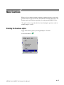
Menu Options . . . . . . . . . . . . . . . . . . . . . . . . . . . . . . . . . . . . . . . . . . . . . . . . . . .
4-- 13
4-- 15
4-- 16
Stream List . . . . . . . . . . . . . . . . . . . . . . . . . . . . . . . . . . . . . . . . . . . . . . .
4--19
Selecting Streams . . . . . . . . . . . . . . . . . . . . . . . . . . . . . . . . . . . . . . . . . . . . . . . .
Processing Streams . . . . . . . . . . . . . . . . . . . . . . . . . . . . . . . . . . . . . . . . . . . . . . .
4-- 21
4-- 21
Event and Message Logs . . . . . . . . . . . . . . . . . . . . . . . . . . . . . . . . . . . .
4--23
Global Event Log . . . . . . . . . . . . . . . . . . . . . . . . . . . . . . . . . . . . . . . . . . . . . . . .
PID Event Log . . . . . . . . . . . . . . . . . . . . . . . . . . . . . . . . . . . . . . . . . . . . . . . . . .
Detail Message Logging . . . . . . . . . . . . . . . . . . . . . . . . . . . . . . . . . . . . . . . . . . .
4-- 23
4-- 24
4-- 25
Results Graphs . . . . . . . . . . . . . . . . . . . . . . . . . . . . . . . . . . . . . . . . . . . .
4--27
Common Features . . . . . . . . . . . . . . . . . . . . . . . . . . . . . . . . . . . . . . . . . . . . . . . .
Elementary Buffer Graph . . . . . . . . . . . . . . . . . . . . . . . . . . . . . . . . . . . . . . . . . .
Multiplex or Main Buffer Graph . . . . . . . . . . . . . . . . . . . . . . . . . . . . . . . . . . . .
Transport Buffer Graph . . . . . . . . . . . . . . . . . . . . . . . . . . . . . . . . . . . . . . . . . . .
Detail Message Logging . . . . . . . . . . . . . . . . . . . . . . . . . . . . . . . . . . . . . . . . . . .
4-- 27
4-- 36
4-- 37
4-- 38
4-- 39
T-STD Buffer Analyzer
Elementary Stream Analyzer
Getting Started . . . . . . . . . . . . . . . . . . . . . . . . . . . . . . . . . . . . . . . . . . . .
5--1
Starting the ES Analyzer . . . . . . . . . . . . . . . . . . . . . . . . . . . . . . . . . . . . . . . . . .
Opening an MPEG Stream . . . . . . . . . . . . . . . . . . . . . . . . . . . . . . . . . . . . . . . . .
Understanding the Main Window and Icons . . . . . . . . . . . . . . . . . . . . . . . . . . .
Tree View and Navigation . . . . . . . . . . . . . . . . . . . . . . . . . . . . . . . . . . . . . . . . .
Header, Extension and Hex Displays . . . . . . . . . . . . . . . . . . . . . . . . . . . . . . . . .
5-- 2
5-- 3
5-- 5
5-- 8
5-- 10
MTS400 Series MPEG Test Systems User Manual
iii
Table of Contents -- Volume 1
iv
Error Testing Methods and Outputs . . . . . . . . . . . . . . . . . . . . . . . . . .
5--15
Run Through Stream Test Mode . . . . . . . . . . . . . . . . . . . . . . . . . . . . . . . . . . . .
Error Filtering . . . . . . . . . . . . . . . . . . . . . . . . . . . . . . . . . . . . . . . . . . . . . . . . . . .
Status Bar . . . . . . . . . . . . . . . . . . . . . . . . . . . . . . . . . . . . . . . . . . . . . . . . . . . . . .
Regression Testing and Error Log Files . . . . . . . . . . . . . . . . . . . . . . . . . . . . . . .
Reports and Field Selection . . . . . . . . . . . . . . . . . . . . . . . . . . . . . . . . . . . . . . . .
Demultiplexing Transport Streams to PES or Elementary Output Files . . . . . .
5-- 16
5-- 17
5-- 23
5-- 24
5-- 27
5-- 30
Working with Transport and PES Streams . . . . . . . . . . . . . . . . . . . .
5--31
Using Packet View . . . . . . . . . . . . . . . . . . . . . . . . . . . . . . . . . . . . . . . . . . . . . . .
Understanding PES . . . . . . . . . . . . . . . . . . . . . . . . . . . . . . . . . . . . . . . . . . . . . . .
5-- 31
5-- 32
Working with Video Streams . . . . . . . . . . . . . . . . . . . . . . . . . . . . . . . .
5--35
Viewing the Sequence Header . . . . . . . . . . . . . . . . . . . . . . . . . . . . . . . . . . . . . .
Viewing the GOP and Picture Header . . . . . . . . . . . . . . . . . . . . . . . . . . . . . . . .
Displaying the Slice and Macroblock . . . . . . . . . . . . . . . . . . . . . . . . . . . . . . . .
Analyzing Picture Quality . . . . . . . . . . . . . . . . . . . . . . . . . . . . . . . . . . . . . . . . .
Using the Video Viewer for Picture Analysis . . . . . . . . . . . . . . . . . . . . . . . . . .
5-- 36
5-- 37
5-- 42
5-- 44
5-- 57
Working with Audio Streams . . . . . . . . . . . . . . . . . . . . . . . . . . . . . . . .
5--61
Understanding MPEG Audio Streams . . . . . . . . . . . . . . . . . . . . . . . . . . . . . . . .
Audio Player . . . . . . . . . . . . . . . . . . . . . . . . . . . . . . . . . . . . . . . . . . . . . . . . . . . .
Understanding Dolby Digital (AC-3) Audio Streams . . . . . . . . . . . . . . . . . . . .
5-- 61
5-- 62
5-- 68
Working with Program Streams . . . . . . . . . . . . . . . . . . . . . . . . . . . . . .
5--71
Viewing Pack and System Headers . . . . . . . . . . . . . . . . . . . . . . . . . . . . . . . . . .
Viewing the Program Stream Map . . . . . . . . . . . . . . . . . . . . . . . . . . . . . . . . . . .
5-- 72
5-- 73
Working with Teletext . . . . . . . . . . . . . . . . . . . . . . . . . . . . . . . . . . . . . .
5--75
VBI (Enhanced Teletext Support) . . . . . . . . . . . . . . . . . . . . . . . . . . . . . . . . . . .
5-- 76
Advanced Audio Compression . . . . . . . . . . . . . . . . . . . . . . . . . . . . . . .
5--79
ADIF Stream Forms . . . . . . . . . . . . . . . . . . . . . . . . . . . . . . . . . . . . . . . . . . . . . .
ADTS Stream Forms . . . . . . . . . . . . . . . . . . . . . . . . . . . . . . . . . . . . . . . . . . . . .
5-- 81
5-- 89
Closed Caption Analysis . . . . . . . . . . . . . . . . . . . . . . . . . . . . . . . . . . . .
5--91
Enabling Closed Caption Analysis . . . . . . . . . . . . . . . . . . . . . . . . . . . . . . . . . . .
Selecting Closed Caption Analysis Standard . . . . . . . . . . . . . . . . . . . . . . . . . . .
CC-EIA608 Support . . . . . . . . . . . . . . . . . . . . . . . . . . . . . . . . . . . . . . . . . . . . . .
CC-EIA708 Support . . . . . . . . . . . . . . . . . . . . . . . . . . . . . . . . . . . . . . . . . . . . . .
Dumping Closed Caption Statistics . . . . . . . . . . . . . . . . . . . . . . . . . . . . . . . . . .
5-- 91
5-- 92
5-- 93
5-- 94
5-- 98
DVB Subtitle Stream Analysis . . . . . . . . . . . . . . . . . . . . . . . . . . . . . . .
5--101
DVB Subtitle Data Tab . . . . . . . . . . . . . . . . . . . . . . . . . . . . . . . . . . . . . . . . . . . .
Page View Tab . . . . . . . . . . . . . . . . . . . . . . . . . . . . . . . . . . . . . . . . . . . . . . . . . .
5-- 103
5-- 106
MTS400 Series MPEG Test Systems User Manual
Table of Contents - Volume 2
General Safety Summary
Service Safety Summary
Preface
xi
xiii
xv
Related Material
Manual Conventions
xv
xvi
Carousel Analyzer
Getting Started . . . . . . . . . . . . . . . . . . . . . . . . . . . . . . . . . . . . . . . . . . . .
6--1
Data Broadcasting Overview . . . . . . . . . . . . . . . . . . . . . . . . . . . . . . . . . . . . . . .
Starting the Program . . . . . . . . . . . . . . . . . . . . . . . . . . . . . . . . . . . . . . . . . . . . . .
6-- 3
6-- 4
Menus and Controls . . . . . . . . . . . . . . . . . . . . . . . . . . . . . . . . . . . . . . .
6--13
Menu Options . . . . . . . . . . . . . . . . . . . . . . . . . . . . . . . . . . . . . . . . . . . . . . . . . . .
Toolbars . . . . . . . . . . . . . . . . . . . . . . . . . . . . . . . . . . . . . . . . . . . . . . . . . . . . . . .
Transport Packet Bar . . . . . . . . . . . . . . . . . . . . . . . . . . . . . . . . . . . . . . . . . . . . .
Status Bar . . . . . . . . . . . . . . . . . . . . . . . . . . . . . . . . . . . . . . . . . . . . . . . . . . . . . .
Workspace . . . . . . . . . . . . . . . . . . . . . . . . . . . . . . . . . . . . . . . . . . . . . . . . . . . . . .
6-- 13
6-- 17
6-- 19
6-- 20
6-- 21
Views . . . . . . . . . . . . . . . . . . . . . . . . . . . . . . . . . . . . . . . . . . . . . . . . . . . .
6--27
Programs/Services View . . . . . . . . . . . . . . . . . . . . . . . . . . . . . . . . . . . . . . . . . . .
Object Carousel View . . . . . . . . . . . . . . . . . . . . . . . . . . . . . . . . . . . . . . . . . . . . .
U-N-Download View . . . . . . . . . . . . . . . . . . . . . . . . . . . . . . . . . . . . . . . . . . . . .
Data Carousel (DVB) View . . . . . . . . . . . . . . . . . . . . . . . . . . . . . . . . . . . . . . . .
Data Carousel (ARIB) View . . . . . . . . . . . . . . . . . . . . . . . . . . . . . . . . . . . . . . . .
Resource View . . . . . . . . . . . . . . . . . . . . . . . . . . . . . . . . . . . . . . . . . . . . . . . . . .
Structure Views . . . . . . . . . . . . . . . . . . . . . . . . . . . . . . . . . . . . . . . . . . . . . . . . . .
Bitrate View . . . . . . . . . . . . . . . . . . . . . . . . . . . . . . . . . . . . . . . . . . . . . . . . . . . .
Repetition View . . . . . . . . . . . . . . . . . . . . . . . . . . . . . . . . . . . . . . . . . . . . . . . . .
PID View . . . . . . . . . . . . . . . . . . . . . . . . . . . . . . . . . . . . . . . . . . . . . . . . . . . . . . .
Log View . . . . . . . . . . . . . . . . . . . . . . . . . . . . . . . . . . . . . . . . . . . . . . . . . . . . . .
Cycle Times View . . . . . . . . . . . . . . . . . . . . . . . . . . . . . . . . . . . . . . . . . . . . . . .
6-- 30
6-- 34
6-- 41
6-- 45
6-- 46
6-- 50
6-- 52
6-- 55
6-- 58
6-- 61
6-- 64
6-- 67
Application Support . . . . . . . . . . . . . . . . . . . . . . . . . . . . . . . . . . . . . . .
6--71
Application Management . . . . . . . . . . . . . . . . . . . . . . . . . . . . . . . . . . . . . . . . . .
Application Definition . . . . . . . . . . . . . . . . . . . . . . . . . . . . . . . . . . . . . . . . . . . .
Application Timing . . . . . . . . . . . . . . . . . . . . . . . . . . . . . . . . . . . . . . . . . . . . . .
6-- 71
6-- 73
6-- 78
MHP Support . . . . . . . . . . . . . . . . . . . . . . . . . . . . . . . . . . . . . . . . . . . . .
6--91
Right-Click Menu Options . . . . . . . . . . . . . . . . . . . . . . . . . . . . . . . . . . . . . . . . .
Application Lifetimes . . . . . . . . . . . . . . . . . . . . . . . . . . . . . . . . . . . . . . . . . . . . .
6-- 92
6-- 93
Reference . . . . . . . . . . . . . . . . . . . . . . . . . . . . . . . . . . . . . . . . . . . . . . . . .
6--95
Script Files . . . . . . . . . . . . . . . . . . . . . . . . . . . . . . . . . . . . . . . . . . . . . . . . . . . . .
Error Checking . . . . . . . . . . . . . . . . . . . . . . . . . . . . . . . . . . . . . . . . . . . . . . . . . .
Acronyms and Abbreviations . . . . . . . . . . . . . . . . . . . . . . . . . . . . . . . . . . . . . . .
References . . . . . . . . . . . . . . . . . . . . . . . . . . . . . . . . . . . . . . . . . . . . . . . . . . . . .
6-- 95
6-- 96
6-- 97
6-- 98
MTS400 Series MPEG Test Systems User Manual
v
Table of Contents -- Volume 2
Carousel Generator
Getting Started . . . . . . . . . . . . . . . . . . . . . . . . . . . . . . . . . . . . . . . . . . . .
7--1
Data Broadcasting Overview . . . . . . . . . . . . . . . . . . . . . . . . . . . . . . . . . . . . . . .
Carousel Generator Overview . . . . . . . . . . . . . . . . . . . . . . . . . . . . . . . . . . . . . .
Starting the Application . . . . . . . . . . . . . . . . . . . . . . . . . . . . . . . . . . . . . . . . . . .
7-- 1
7-- 2
7-- 6
Carousel Wizard . . . . . . . . . . . . . . . . . . . . . . . . . . . . . . . . . . . . . . . . . .
7--9
Step 1: Select Carousel . . . . . . . . . . . . . . . . . . . . . . . . . . . . . . . . . . . . . . . . . . . .
Step 2: Carousel Properties . . . . . . . . . . . . . . . . . . . . . . . . . . . . . . . . . . . . . . . .
Step 3: Carousel Contents . . . . . . . . . . . . . . . . . . . . . . . . . . . . . . . . . . . . . . . . .
Step 4: Collection Contents . . . . . . . . . . . . . . . . . . . . . . . . . . . . . . . . . . . . . . . .
Step 5: Imported Elementary Streams . . . . . . . . . . . . . . . . . . . . . . . . . . . . . . . .
Step 6: Program Entry . . . . . . . . . . . . . . . . . . . . . . . . . . . . . . . . . . . . . . . . . . . .
Step 7: Output Stream Properties . . . . . . . . . . . . . . . . . . . . . . . . . . . . . . . . . . . .
Step 8: Congratulations . . . . . . . . . . . . . . . . . . . . . . . . . . . . . . . . . . . . . . . . . . .
7-- 11
7-- 12
7-- 13
7-- 15
7-- 18
7-- 20
7-- 21
7-- 22
Menus and Controls . . . . . . . . . . . . . . . . . . . . . . . . . . . . . . . . . . . . . . .
7--23
Menus Options . . . . . . . . . . . . . . . . . . . . . . . . . . . . . . . . . . . . . . . . . . . . . . . . . .
Toolbars . . . . . . . . . . . . . . . . . . . . . . . . . . . . . . . . . . . . . . . . . . . . . . . . . . . . . . .
Log Window . . . . . . . . . . . . . . . . . . . . . . . . . . . . . . . . . . . . . . . . . . . . . . . . . . . .
Status Bar . . . . . . . . . . . . . . . . . . . . . . . . . . . . . . . . . . . . . . . . . . . . . . . . . . . . . .
Properties Window (List Control) . . . . . . . . . . . . . . . . . . . . . . . . . . . . . . . . . . .
7-- 23
7-- 27
7-- 30
7-- 31
7-- 31
Carousel Generation . . . . . . . . . . . . . . . . . . . . . . . . . . . . . . . . . . . . . . .
7--33
Setting Overall Carousel Generator Properties . . . . . . . . . . . . . . . . . . . . . . . . .
Creating a Session . . . . . . . . . . . . . . . . . . . . . . . . . . . . . . . . . . . . . . . . . . . . . . .
Selecting the Carousel Type . . . . . . . . . . . . . . . . . . . . . . . . . . . . . . . . . . . . . . . .
Modifying the Carousel Properties . . . . . . . . . . . . . . . . . . . . . . . . . . . . . . . . . . .
Carousel Contents . . . . . . . . . . . . . . . . . . . . . . . . . . . . . . . . . . . . . . . . . . . . . . . .
Collections . . . . . . . . . . . . . . . . . . . . . . . . . . . . . . . . . . . . . . . . . . . . . . . . . . . . .
Programs . . . . . . . . . . . . . . . . . . . . . . . . . . . . . . . . . . . . . . . . . . . . . . . . . . . . . . .
Output Stream Generation . . . . . . . . . . . . . . . . . . . . . . . . . . . . . . . . . . . . . . . . .
Carousel Definition File . . . . . . . . . . . . . . . . . . . . . . . . . . . . . . . . . . . . . . . . . . .
7-- 33
7-- 39
7-- 41
7-- 42
7-- 51
7-- 66
7-- 70
7-- 79
7-- 79
PSI and SI in the Carousel Generator Output Stream . . . . . . . . . . .
7--81
PSI/SI Mode Settings . . . . . . . . . . . . . . . . . . . . . . . . . . . . . . . . . . . . . . . . . . . . .
MPEG PSI tables . . . . . . . . . . . . . . . . . . . . . . . . . . . . . . . . . . . . . . . . . . . . . . . .
DVB SI Tables . . . . . . . . . . . . . . . . . . . . . . . . . . . . . . . . . . . . . . . . . . . . . . . . . .
Summary . . . . . . . . . . . . . . . . . . . . . . . . . . . . . . . . . . . . . . . . . . . . . . . . . . . . . . .
7-- 81
7-- 82
7-- 89
7-- 103
Getting Started . . . . . . . . . . . . . . . . . . . . . . . . . . . . . . . . . . . . . . . . . . . .
8--1
Starting the Program . . . . . . . . . . . . . . . . . . . . . . . . . . . . . . . . . . . . . . . . . . . . . .
Scripts . . . . . . . . . . . . . . . . . . . . . . . . . . . . . . . . . . . . . . . . . . . . . . . . . . . . . . . . .
Opening a Stream . . . . . . . . . . . . . . . . . . . . . . . . . . . . . . . . . . . . . . . . . . . . . . . .
Closing Files . . . . . . . . . . . . . . . . . . . . . . . . . . . . . . . . . . . . . . . . . . . . . . . . . . . .
8-- 3
8-- 5
8-- 9
8-- 14
Menus and Controls . . . . . . . . . . . . . . . . . . . . . . . . . . . . . . . . . . . . . . .
8--15
Menu Options . . . . . . . . . . . . . . . . . . . . . . . . . . . . . . . . . . . . . . . . . . . . . . . . . . .
Toolbar . . . . . . . . . . . . . . . . . . . . . . . . . . . . . . . . . . . . . . . . . . . . . . . . . . . . . . . .
Status Bar . . . . . . . . . . . . . . . . . . . . . . . . . . . . . . . . . . . . . . . . . . . . . . . . . . . . . .
User Interface . . . . . . . . . . . . . . . . . . . . . . . . . . . . . . . . . . . . . . . . . . . . . . . . . . .
8-- 15
8-- 19
8-- 20
8-- 21
Multiplexer
vi
MTS400 Series MPEG Test Systems User Manual
Table of Contents -- Volume 2
Wizards . . . . . . . . . . . . . . . . . . . . . . . . . . . . . . . . . . . . . . . . . . . . . . . . . .
8--27
Transport Wizard . . . . . . . . . . . . . . . . . . . . . . . . . . . . . . . . . . . . . . . . . . . . . . . .
Program Wizard . . . . . . . . . . . . . . . . . . . . . . . . . . . . . . . . . . . . . . . . . . . . . . . . .
8-- 28
8-- 33
Views . . . . . . . . . . . . . . . . . . . . . . . . . . . . . . . . . . . . . . . . . . . . . . . . . . . .
8--43
Navigator Views . . . . . . . . . . . . . . . . . . . . . . . . . . . . . . . . . . . . . . . . . . . . . . . . .
Section View . . . . . . . . . . . . . . . . . . . . . . . . . . . . . . . . . . . . . . . . . . . . . . . . . . . .
Structure Diagram Manipulation . . . . . . . . . . . . . . . . . . . . . . . . . . . . . . . . . . . .
Event Log . . . . . . . . . . . . . . . . . . . . . . . . . . . . . . . . . . . . . . . . . . . . . . . . . . . . . .
Examine Transport Stream Window . . . . . . . . . . . . . . . . . . . . . . . . . . . . . . . . .
SI Filtering . . . . . . . . . . . . . . . . . . . . . . . . . . . . . . . . . . . . . . . . . . . . . . . . . . . . .
Component Views . . . . . . . . . . . . . . . . . . . . . . . . . . . . . . . . . . . . . . . . . . . . . . . .
Common Menu Options . . . . . . . . . . . . . . . . . . . . . . . . . . . . . . . . . . . . . . . . . . .
8-- 44
8-- 47
8-- 56
8-- 57
8-- 58
8-- 61
8-- 65
8-- 74
Editing in the Navigator Views . . . . . . . . . . . . . . . . . . . . . . . . . . . . . . .
8--75
Drag and Drop . . . . . . . . . . . . . . . . . . . . . . . . . . . . . . . . . . . . . . . . . . . . . . . . . .
Transport Stream . . . . . . . . . . . . . . . . . . . . . . . . . . . . . . . . . . . . . . . . . . . . . . . .
Programs . . . . . . . . . . . . . . . . . . . . . . . . . . . . . . . . . . . . . . . . . . . . . . . . . . . . . . .
Tables . . . . . . . . . . . . . . . . . . . . . . . . . . . . . . . . . . . . . . . . . . . . . . . . . . . . . . . . .
Sections . . . . . . . . . . . . . . . . . . . . . . . . . . . . . . . . . . . . . . . . . . . . . . . . . . . . . . . .
ES PIDs . . . . . . . . . . . . . . . . . . . . . . . . . . . . . . . . . . . . . . . . . . . . . . . . . . . . . . . .
DSM-CC . . . . . . . . . . . . . . . . . . . . . . . . . . . . . . . . . . . . . . . . . . . . . . . . . . . . . . .
8-- 75
8-- 76
8-- 77
8-- 79
8-- 82
8-- 91
8-- 100
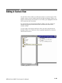
Editing in Section View . . . . . . . . . . . . . . . . . . . . . . . . . . . . . . . . . . . . .
8--103
Editing Fields . . . . . . . . . . . . . . . . . . . . . . . . . . . . . . . . . . . . . . . . . . . . . . . . . . .
8-- 104
Multiplexing Transport Streams . . . . . . . . . . . . . . . . . . . . . . . . . . . . .
8--111
Start . . . . . . . . . . . . . . . . . . . . . . . . . . . . . . . . . . . . . . . . . . . . . . . . . . . . . . . . . . .
Errors and Reporting . . . . . . . . . . . . . . . . . . . . . . . . . . . . . . . . . . . . . . . . . . . . .
Stop . . . . . . . . . . . . . . . . . . . . . . . . . . . . . . . . . . . . . . . . . . . . . . . . . . . . . . . . . . .
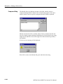
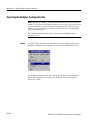
Exporting the Multiplex Configuration File . . . . . . . . . . . . . . . . . . . . . . . . . . .
8-- 111
8-- 112
8-- 113
8-- 114
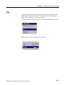
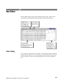
Make Seamless . . . . . . . . . . . . . . . . . . . . . . . . . . . . . . . . . . . . . . . . . . . .
8--117
Enabling the Seamless option . . . . . . . . . . . . . . . . . . . . . . . . . . . . . . . . . . . . . .
Seamless Settings . . . . . . . . . . . . . . . . . . . . . . . . . . . . . . . . . . . . . . . . . . . . . . . .
8-- 117
8-- 118
Reference . . . . . . . . . . . . . . . . . . . . . . . . . . . . . . . . . . . . . . . . . . . . . . . . .
8--119
Abbreviations . . . . . . . . . . . . . . . . . . . . . . . . . . . . . . . . . . . . . . . . . . . . . . . . . . .
8-- 119
Transport Stream Editor
Getting Started . . . . . . . . . . . . . . . . . . . . . . . . . . . . . . . . . . . . . . . . . . . .
9--1
Starting the Program . . . . . . . . . . . . . . . . . . . . . . . . . . . . . . . . . . . . . . . . . . . . . .
Options . . . . . . . . . . . . . . . . . . . . . . . . . . . . . . . . . . . . . . . . . . . . . . . . . . . . . . . .
Opening a File . . . . . . . . . . . . . . . . . . . . . . . . . . . . . . . . . . . . . . . . . . . . . . . . . .
9-- 2
9-- 3
9-- 4
Menus and Controls . . . . . . . . . . . . . . . . . . . . . . . . . . . . . . . . . . . . . . .
9--7
Toolbar . . . . . . . . . . . . . . . . . . . . . . . . . . . . . . . . . . . . . . . . . . . . . . . . . . . . . . . .
Status Bar . . . . . . . . . . . . . . . . . . . . . . . . . . . . . . . . . . . . . . . . . . . . . . . . . . . . . .
Slider Bar . . . . . . . . . . . . . . . . . . . . . . . . . . . . . . . . . . . . . . . . . . . . . . . . . . . . . .
Menu Options . . . . . . . . . . . . . . . . . . . . . . . . . . . . . . . . . . . . . . . . . . . . . . . . . . .
9-- 7
9-- 8
9-- 9
9-- 11
Hex Editor . . . . . . . . . . . . . . . . . . . . . . . . . . . . . . . . . . . . . . . . . . . . . . .
9--15
Color Coding . . . . . . . . . . . . . . . . . . . . . . . . . . . . . . . . . . . . . . . . . . . . . . . . . . .
Selecting & Editing . . . . . . . . . . . . . . . . . . . . . . . . . . . . . . . . . . . . . . . . . . . . . .
9-- 15
9-- 17
MTS400 Series MPEG Test Systems User Manual
vii
Table of Contents -- Volume 2
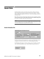
Header Editor . . . . . . . . . . . . . . . . . . . . . . . . . . . . . . . . . . . . . . . . . . . . .
9--21
Header Information Tab . . . . . . . . . . . . . . . . . . . . . . . . . . . . . . . . . . . . . . . . . . .
Adaptation Field Tab . . . . . . . . . . . . . . . . . . . . . . . . . . . . . . . . . . . . . . . . . . . . .
Adaptation Field Extension Tab . . . . . . . . . . . . . . . . . . . . . . . . . . . . . . . . . . . . .
9-- 21
9-- 23
9-- 26
PID Remapping . . . . . . . . . . . . . . . . . . . . . . . . . . . . . . . . . . . . . . . . . . .
PCR Recalculation . . . . . . . . . . . . . . . . . . . . . . . . . . . . . . . . . . . . . . . . .
9--29
9--33
Jitter Functions . . . . . . . . . . . . . . . . . . . . . . . . . . . . . . . . . . . . . . . . . . . . . . . . . .
9-- 38
Getting Started . . . . . . . . . . . . . . . . . . . . . . . . . . . . . . . . . . . . . . . . . . . .
10--1
Display Elements . . . . . . . . . . . . . . . . . . . . . . . . . . . . . . . . . . . . . . . . . . . . . . . .
Hierarchical Display . . . . . . . . . . . . . . . . . . . . . . . . . . . . . . . . . . . . . . . . . . . . . .
10-- 1
10-- 7
Menus and Controls . . . . . . . . . . . . . . . . . . . . . . . . . . . . . . . . . . . . . . .
10--19
Menus in the Play Screen . . . . . . . . . . . . . . . . . . . . . . . . . . . . . . . . . . . . . . . . . .
Menus in the Record Screen . . . . . . . . . . . . . . . . . . . . . . . . . . . . . . . . . . . . . . . .
Toolbar Buttons . . . . . . . . . . . . . . . . . . . . . . . . . . . . . . . . . . . . . . . . . . . . . . . . .
10-- 19
10-- 37
10-- 42
Reference . . . . . . . . . . . . . . . . . . . . . . . . . . . . . . . . . . . . . . . . . . . . . . . . .
10--45
Interface Card (SPI/ASI/310M Option) . . . . . . . . . . . . . . . . . . . . . . . . . . . . . . .
Adding Jitter to PCRs . . . . . . . . . . . . . . . . . . . . . . . . . . . . . . . . . . . . . . . . . . . . .
Using Preset Files . . . . . . . . . . . . . . . . . . . . . . . . . . . . . . . . . . . . . . . . . . . . . . . .
Using the Continuous Recording Feature . . . . . . . . . . . . . . . . . . . . . . . . . . . . .
Performing Continuous Recording . . . . . . . . . . . . . . . . . . . . . . . . . . . . . . . . . . .
Remote Commands . . . . . . . . . . . . . . . . . . . . . . . . . . . . . . . . . . . . . . . . . . . . . .
10-- 45
10-- 46
10-- 49
10-- 50
10-- 52
10-- 54
Getting Started . . . . . . . . . . . . . . . . . . . . . . . . . . . . . . . . . . . . . . . . . . . .
11--1
Important Information about Tracer . . . . . . . . . . . . . . . . . . . . . . . . . . . . . . . . . .
Setting Up Tracer and Buffer Analyzer . . . . . . . . . . . . . . . . . . . . . . . . . . . . . . .
Starting Tracer . . . . . . . . . . . . . . . . . . . . . . . . . . . . . . . . . . . . . . . . . . . . . . . . . .
User Interface . . . . . . . . . . . . . . . . . . . . . . . . . . . . . . . . . . . . . . . . . . . . . . . . . . .
11-- 1
11-- 2
11-- 4
11-- 4
Menus and Controls . . . . . . . . . . . . . . . . . . . . . . . . . . . . . . . . . . . . . . .
11--11
File Menu Options . . . . . . . . . . . . . . . . . . . . . . . . . . . . . . . . . . . . . . . . . . . . . . .
Edit Menu Options . . . . . . . . . . . . . . . . . . . . . . . . . . . . . . . . . . . . . . . . . . . . . . .
Print Menu Options . . . . . . . . . . . . . . . . . . . . . . . . . . . . . . . . . . . . . . . . . . . . . .
View Menu Options . . . . . . . . . . . . . . . . . . . . . . . . . . . . . . . . . . . . . . . . . . . . . .
Show Menu Options . . . . . . . . . . . . . . . . . . . . . . . . . . . . . . . . . . . . . . . . . . . . . .
Help Menu Options . . . . . . . . . . . . . . . . . . . . . . . . . . . . . . . . . . . . . . . . . . . . . .
11-- 11
11-- 12
11-- 13
11-- 14
11-- 15
11-- 16
MPEG Player
Tracer
Make Seamless Wizard
viii
Make Seamless Wizard . . . . . . . . . . . . . . . . . . . . . . . . . . . . . . . . . . . . .
12--1
Starting the Wizard . . . . . . . . . . . . . . . . . . . . . . . . . . . . . . . . . . . . . . . . . . . . . . .
Selecting an Input File . . . . . . . . . . . . . . . . . . . . . . . . . . . . . . . . . . . . . . . . . . . .
Select a Program to Make Seamless . . . . . . . . . . . . . . . . . . . . . . . . . . . . . . . . .
Selecting a Multiplex Output File . . . . . . . . . . . . . . . . . . . . . . . . . . . . . . . . . . .
12-- 1
12-- 2
12-- 7
12-- 10
MTS400 Series MPEG Test Systems User Manual
Table of Contents -- Volume 2
Transport Stream Cutter
Transport Stream Cutter . . . . . . . . . . . . . . . . . . . . . . . . . . . . . . . . . . .
13--1
Starting the Wizard . . . . . . . . . . . . . . . . . . . . . . . . . . . . . . . . . . . . . . . . . . . . . . .
Cutting a File . . . . . . . . . . . . . . . . . . . . . . . . . . . . . . . . . . . . . . . . . . . . . . . . . . .
13-- 1
13-- 2
Getting Started . . . . . . . . . . . . . . . . . . . . . . . . . . . . . . . . . . . . . . . . . . . .
14--1
Setting Up . . . . . . . . . . . . . . . . . . . . . . . . . . . . . . . . . . . . . . . . . . . . . . . . . . . . . .
Starting the Program . . . . . . . . . . . . . . . . . . . . . . . . . . . . . . . . . . . . . . . . . . . . . .
Initial Appearance . . . . . . . . . . . . . . . . . . . . . . . . . . . . . . . . . . . . . . . . . . . . . . .
Initial Menu Options . . . . . . . . . . . . . . . . . . . . . . . . . . . . . . . . . . . . . . . . . . . . . .
Script File Appearance . . . . . . . . . . . . . . . . . . . . . . . . . . . . . . . . . . . . . . . . . . . .
Opening a File . . . . . . . . . . . . . . . . . . . . . . . . . . . . . . . . . . . . . . . . . . . . . . . . . .
14-- 1
14-- 1
14-- 2
14-- 3
14-- 3
14-- 4
Menu and Controls . . . . . . . . . . . . . . . . . . . . . . . . . . . . . . . . . . . . . . . .
14--7
Menu Bar . . . . . . . . . . . . . . . . . . . . . . . . . . . . . . . . . . . . . . . . . . . . . . . . . . . . . .
Toolbar . . . . . . . . . . . . . . . . . . . . . . . . . . . . . . . . . . . . . . . . . . . . . . . . . . . . . . . .
Status Bar . . . . . . . . . . . . . . . . . . . . . . . . . . . . . . . . . . . . . . . . . . . . . . . . . . . . . .
14-- 7
14-- 9
14-- 10
Script File Editing and Encryption . . . . . . . . . . . . . . . . . . . . . . . . . . .
14--11
Keyword Color-Coding . . . . . . . . . . . . . . . . . . . . . . . . . . . . . . . . . . . . . . . . . . .
Parsing . . . . . . . . . . . . . . . . . . . . . . . . . . . . . . . . . . . . . . . . . . . . . . . . . . . . . . . .
Encryption . . . . . . . . . . . . . . . . . . . . . . . . . . . . . . . . . . . . . . . . . . . . . . . . . . . . .
14-- 11
14-- 11
14-- 12
Script Pad
Glossary
MTS400 Series MPEG Test Systems User Manual
ix
General Safety Summary
Review the following safety precautions to avoid injury and prevent damage to
this product or any products connected to it.
To avoid potential hazards, use this product only as specified.
Only qualified personnel should perform service procedures.
To Avoid Fire or
Personal Injury
Use Proper Power Cord. Use only the power cord specified for this product and
certified for the country of use.
Ground the Product. This product is grounded through the grounding conductor
of the power cord. To avoid electric shock, the grounding conductor must be
connected to earth ground. Before making connections to the input or output
terminals of the product, ensure that the product is properly grounded.
Observe All Terminal Ratings. To avoid fire or shock hazard, observe all ratings
and markings on the product. Consult the product manual for further ratings
information before making connections to the product.
Power Disconnect. The power cord disconnects the product from the power
source. Do not block the power cord; it must remain accessible to the user at all
times.
Do Not Operate Without Covers. Do not operate this product with covers or panels
removed.
Do Not Operate With Suspected Failures. If you suspect there is damage to this
product, have it inspected by qualified service personnel.
Avoid Exposed Circuitry. Do not touch exposed connections and components
when power is present.
Use Proper Fuse. Use only the fuse type and rating specified for this product.
Do Not Operate in Wet/Damp Conditions.
Do Not Operate in an Explosive Atmosphere.
Keep Product Surfaces Clean and Dry.
Provide Proper Ventilation. Refer to the manual’s installation instructions for
details on installing the product so it has proper ventilation.
MTS400 Series MPEG Test Systems User Manual
xi
General Safety Summary
Terms in this Manual
These terms may appear in this manual:
WARNING. Warning statements identify conditions or practices that could result
in injury or loss of life.
CAUTION. Caution statements identify conditions or practices that could result in
damage to this product or other property.
Symbols and Terms
on the Product
These terms may appear on the product:
H
DANGER indicates an injury hazard immediately accessible as you read the
marking.
H
WARNING indicates an injury hazard not immediately accessible as you
read the marking.
H
CAUTION indicates a hazard to property including the product.
The following symbols may appear on the product:
CAUTION
Refer to Manual
xii
Protective Ground
(Earth) Terminal
MTS400 Series MPEG Test Systems User Manual
Service Safety Summary
Only qualified personnel should perform service procedures. Read this Service
Safety Summary and the General Safety Summary before performing any service
procedures.
Do Not Service Alone. Do not perform internal service or adjustments of this
product unless another person capable of rendering first aid and resuscitation is
present.
Disconnect Power. To avoid electric shock, switch off the instrument power, then
disconnect the power cord from the mains power.
Use Care When Servicing With Power On. Dangerous voltages or currents may
exist in this product. Disconnect power, remove battery (if applicable), and
disconnect test leads before removing protective panels, soldering, or replacing
components.
To avoid electric shock, do not touch exposed connections.
MTS400 Series MPEG Test Systems User Manual
xiii
Preface
This manual describes the functions and use of the MTS400 Series
MPEG Test System. After the introduction, each section of the manual describes
one of the software applications or tools that make up the MTS400 Series
system.
H
MTS400 Series MPEG Test System Getting Started Manual (071-1505-xx).
H
MTS400 Series MPEG Test System Programmer Manual (071-1725-xx).
This manual specifies the remote control and status monitoring interfaces
available to a management application.
Related Material
Additional documentation, such as Read Me files, may be included on the
installation disks.
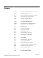
The following URLs access the Web sites for the standards organizations listed
(the URLs listed were valid at the time of writing):
H
MPEG-2 standards (International Organization for Standards)
http://www.iso.ch/
H
DVB standards (European Technical Standards Institute)
http://www.etsi.org/
H
ATSC standards (Advanced Television Systems Committee)
http://www.atsc.org/
H
ISDB/ARIB standards (Association of Radio Industries and Businesses)
http://www.arib.or.jp/english/
H
SCTE Society of Cable Television Engineers
http://www.scte.org/
MTS400 Series MPEG Test Systems User Manual
xv
Preface
Manual Conventions
Naming conventions for the interface elements are based on standard Microsoft
Windows naming conventions. Naming conventions for MPEG--2, ATSC, and
DVB structures follow the conventions derived from the standards listed above.
In addition, the following formatting conventions apply to this manual:
H
Bold text refers to specific interface elements that you are instructed to
select, click, or clear.
Example: Select Settings from the Configuration menu.
H
Mono--spaced text can indicate the following:
H
Text you enter from a keyboard
Example: Enter the network identity (http://TSMonitor01)
H
Characters you press on your keyboard
Example: Press CTRL+C to copy the selected text.
H
Paths to components on your hard drive
Example: The program files are installed at the following location:
C:\Program Files\Tektronix\
xvi
MTS400 Series MPEG Test Systems User Manual
Carousel Analyzer
Getting Started
The Digital Storage Media Command and Control (DSM-CC) protocol was
originally developed to provide a VCR-like control mechanism for program
material delivered in an MPEG2 transport stream. Since then, the standard has
evolved to encompass a wide variety of applications including data broadcasting
and interactive television. DSM-CC forms a core part of a variety of both closed
and open standards such as the DVB MHP (Multimedia Home Platform)
standard for European Interactive Television.
The following DTV standards are supported:
(See page 6--98 for details of all references in this section.)
H
ISO/IEC 13818-6 Information technology - Generic coding of moving
pictures and associated audio information - Part 6: Extension for Digital
Storage Media Command and Control [MPEG] (Reference [2])
H
EN 301 192 Specification for data broadcasting [DVB] (Reference [4])
H
ARIB STD - B24 Data Coding and Transmission Specification for Digital
Broadcasting (Reference [11])
H
Multimedia Home Platform [DVB] (Reference [12])
A bibliography of DTV standards documentation is given in the Reference
section.
The Carousel Analyzer has been developed to meet the specific need
to analyze and display the content and structure of data broadcasts. The tool
provides a variety of ways of looking at a transport stream and its contents
including displaying the bit rate, repetition rates, structure, syntax, and semantics
of data items.
MTS400 Series MPEG Test Systems User Manual
6- 1
Carousel Analyzer - Getting Started
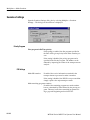
The program view shows the various services in the transport stream and their
associated PIDs and data streams. Object or data (one or two layer) carousels and
U-U or U-N messages such as DSM-CC Download can also be displayed with
options to view associated, sections, carrier modules, or transport packets for
each version as required.
An object carousel in the stream can be viewed by contents as a directory
structure containing the underlying objects such as Java classes, picture, or text
files. If an object is associated with an installed application then a double-click
will launch that program, providing, for example, an easy and quick way to view
the contents of a picture file or read a text file.
The structure of the U-N download messages can be viewed showing the
relationship between DII, modules and blocks. The associated DSI and DII
messages contained in the U-N-Download tables can also be viewed in interpreted or hex fashion; these indicate where to find and view the BIOPs that
contain a required object in the stream.
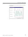
The timing relationships between the various components can also be easily
shown because the bit rates or the repetition rates of blocks, modules, objects,
U-N messages or SI tables can be shown together in a single graphical display.
6- 2
MTS400 Series MPEG Test Systems User Manual
Carousel Analyzer - Getting Started
Data Broadcasting Overview
Data Broadcasting allows data to be transmitted in asimilar way to the way in
which video and audio services are delivered to end users. Object and Data
Carousels are intended for the periodic transmission of information in a transport
stream. DVB Data Carousels contain modules of data of unspecified content.
ARIB Data Carousels and Object Carousels contain identifiable data objects, for
example, JPEG files, text files, and application software. Multimedia Home
Platform (MHP) is also supported because the Application Information Table
(AIT) and Object Carousels (as specified in the MHP standard) can be viewed.
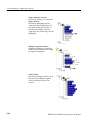
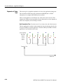
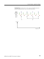
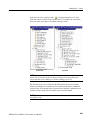
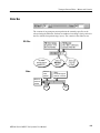
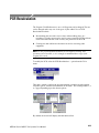
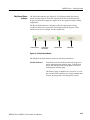
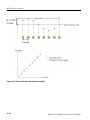
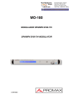
The diagram below shows how information carried by data and object carousels
is subdivided and ultimately carried by the transport stream.
Object Carousel:
BIOP Messages
Download Data
Carousel:
Modules and
Blocks
DSM--CC Sections
BIOP 1
BIOP 2
BIOP 3
BIOP 4
Module 1
Block 1
Section 1
Block 2
Section 2
Block 3
Section 3
Block 4
Section 4
Block 5
Section 5
Transport Packets
Headers are
shown shaded.
BIOP messages contain a message header, a message sub-header and the
message body which contains data. The message body may contain complete
data objects.
BIOP messages are broadcast in Modules. A Module is formed from one or more
concatenated, complete BIOP messages.
Each Module is fragmented into one or more Download Data Blocks which are
in turn transmitted in corresponding DSM-CC Sections.
Sections are transmitted in packets in the Transport Stream.
The Carousel Analyzer enables each layer of the protocol stack to be analyzed
and inspected. The following sections provide an overview of how the Carousel
Analyzer can be used to locate messages and packets of interest.
MTS400 Series MPEG Test Systems User Manual
6- 3
Carousel Analyzer - Getting Started
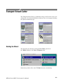
Starting the Program
The program can be started by selecting the Carousel Analyzer
option from the Start > Programs > Tektronix Data Applications V2.0 menu
or by double clicking on the Carousel Analyzer shortcut on the
desktop.
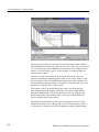
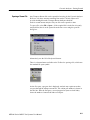
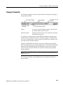
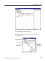
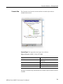
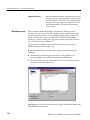
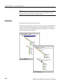
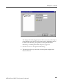
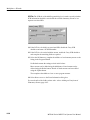
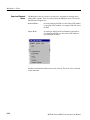
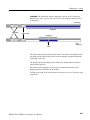
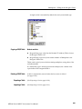
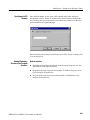
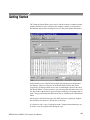
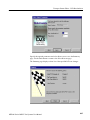
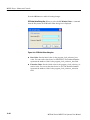
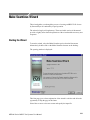
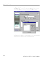
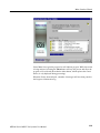
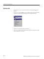
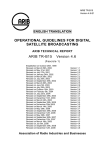
Initial Appearance
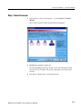
When the program has started and is ready for use, it will open the Main
window, as shown in Figure 6--1:
Menu bar
Toolbars
Workspace
Transport
packet bar
Status bar
DTV standard
Figure 6- 1: Main Window - Intial Appearance
6- 4
MTS400 Series MPEG Test Systems User Manual
Carousel Analyzer - Getting Started
Elements of the main window can be hidden during a session, but will be
restored at start-up.
The Menu Bar contains all options available to the application; disabled options
are visible but grayed out. The Toolbars provide shortcuts to the more important
menu options; similarly, disabled buttons are visible but grayed out. The
Transport Packet Bar provides controls to locate and jump to transport packets.
The Status Bar shows stream information and the cursor message field.
Initial Menu Options
The Carousel Analyzer presents different menus and options depending upon
whether or not a stream is open for analysis. The menu options available when
no stream is open are as follows:
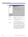
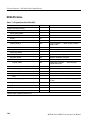
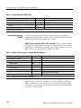
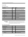
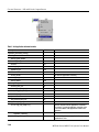
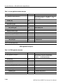
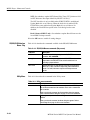
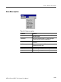
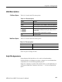
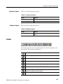
File Menu Options. Table 6--1 lists the options in the initial File menu.
Table 6- 1: File menu options
Option
Function
Open...
Opens an MPEG transport stream for analysis. The program
opens the file selection dialogue allowing the user to choose
the required file.
Print Setup...
Opens a dialog for selecting which printer and associated
options to use.
1 <<filename>>
2 <<filename>>
3 <<filename>>
4 <<filename>>
A list of the four most recently analyzed files. If the program
has recently been installed, the list may be empty or hold less
than four files.
Exit
Finishes running the program.
Selecting a filename opens that file for analysis.
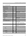
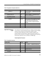
View Menu Options. Table 6--2 lists the options in the initial View menu.
Table 6- 2: View menu options
Option
Function
Toolbars >
Submenu shows or hides the toolbar.
Transport Packet Bar
Shows or hides the Transport Packet Bar.
Status Bar
Shows or hides the status bar.
MTS400 Series MPEG Test Systems User Manual
6- 5
Carousel Analyzer - Getting Started
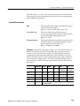
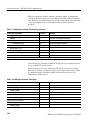
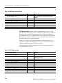
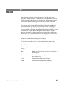
Analysis Menu Options. Table 6--3 lists the options in the initial Analysis menu.
Table 6- 3: Analysis menu options
Stream Interpretation
Option
Function
Set Interpretation >
Select the Digital TV standard to be used for stream analysis.
Settings...
Displays a dialog for selecting scripts to be used during
analysis.
The DTV standard to be used for analysis must be selected before any streams
are opened.
Select the required standard from the submenu.
Script Selection And
Manipulation
Scripts are available to the Carousel Analyzer to enable structures to be analyzed
successfully.
If any script is not selected or enabled, the stream will not fail to be analyzed,
but any data normally interpreted by that script would be ignored.
Scripts can only be selected and enabled when no files are open. The option is
not available when a file is open.
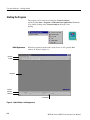
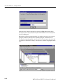
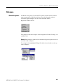
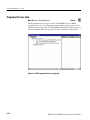
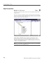
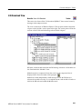
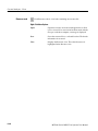
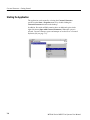
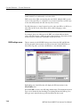
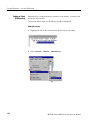
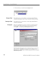
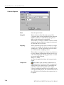
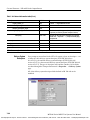
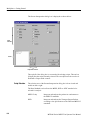
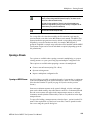
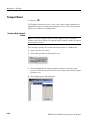
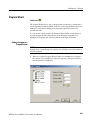
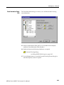
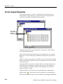
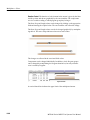
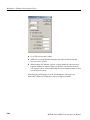
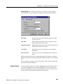
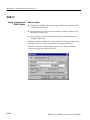
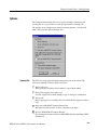
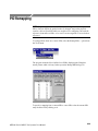
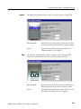
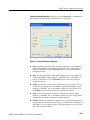
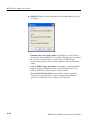
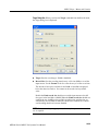
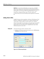
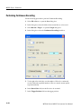
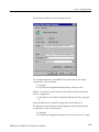
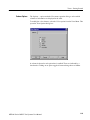
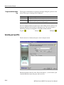
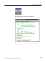
Handling Script Files. To open the Analysis Settings dialog box, select Settings...
from the Analysis menu.
6- 6
MTS400 Series MPEG Test Systems User Manual
Carousel Analyzer - Getting Started
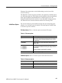
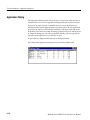
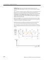
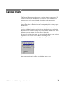
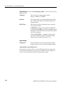
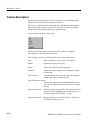
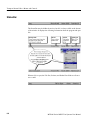
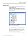
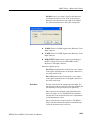
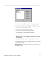
The dialog box shown below is displayed:
In the Analysis Settings dialog, the left window shows a tree structure of the test
protocols available. The right window shows the scripts currently allocated to the
test protocol; in the example, the listed scripts are associated with the DVB Section protocol. The right window also contains the controls needed to
manipulate the scripts.
Note that across the standards, the scripts are not hierarchical; that is, each DTV
standard must be self-contained in terms of the scripts that it uses.
The currently available script files are listed in the Reference section
(page 6--98).
The following paragraphs describe the available script manipulation activities.
The activities are applied to the currently selected test protocol.
MTS400 Series MPEG Test Systems User Manual
6- 7
Carousel Analyzer - Getting Started
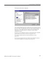
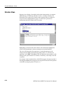
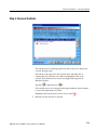
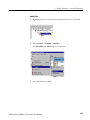
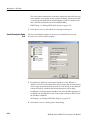
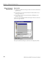
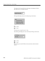
Adding a Script file.
1. With the required test protocol highlighted, select the Add New Script button
(Shortcut key: Insert).
2. If the script path/name is known, enter it into the blank field.
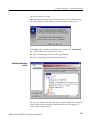
If the script name is unknown, use the browse button at the right side of the
blank field to display a standard Windows file Open dialog box.
3. The new script file name will be added at the bottom of the script list. Note
that script files are parsed in the order that they are listed, because the file
may require moving up in the list – see Moving Script files in the list below.
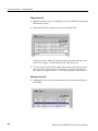
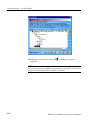
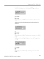
Removing a Script File.
1. Highlight the file to be deleted and select the Delete Script button (Shortcut
key: Delete).
6- 8
MTS400 Series MPEG Test Systems User Manual
Carousel Analyzer - Getting Started
Moving Script Files in the List Script files are parsed in the order that they are
listed; the file may require moving up in the list
1. Highlight the file to be moved and select either the Move Up or Move Down
button (Shortcut keys: Alt-Y and Alt-B respectively). The file will move up
or down one place for each press of the button.
Syntax Checking Options
A number of options are available from the Analysis Settings dialog that allow
strict syntax checking to be enabled and disabled.
If any option is not enabled, the relevant syntax will not fail to be checked, but
will be interpreted more loosely.
Syntax Checking Options can only be selected and enabled when no files are
open. The option is not available when a file is open.
Currently, three syntax checking options are available:
Strict private data length/Message length checking. Object: U-U Object Carousel
Disabling this option allows the privateDataLength field where it exists in the
DSI to be set to zero. The application will calculate it when required, using the
total message length and the position of the private data in the message.
(See reference [2], sections 2 and 7.3.6.)
Strict association tag checking. Object: U-U Object Carousel
The association tag field in the stream_identifier_descriptor is an 8-bit value,
while the same field in an object carousel is a 16-bit value. When comparing
these two values, the MSB of the 16-bit value should be zero. Disabling this
option allows it to take other values.
(See reference [4], 9.3 paragraph 3 and [6], paragraph 4.7.7.3.)
MTS400 Series MPEG Test Systems User Manual
6- 9
Carousel Analyzer - Getting Started
Strict CRC/Checksum checking. Object: DSM-CC Section
section_syntax_indicator and private_indicator fields should be the complement
of each other to determine whether a CRC or checksum is in use. Disabling this
option allows them to be the same and allows the application to work out which
method should be applied.
(See reference [2], section 9.2.2 paragraphs 3 and 4.)
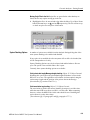
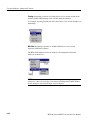
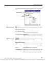
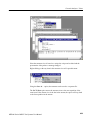
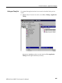
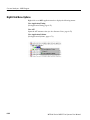
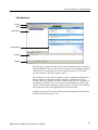
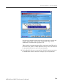
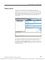
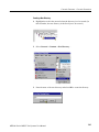
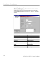
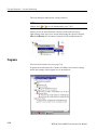
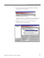
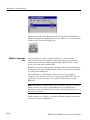
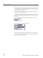
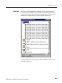
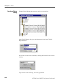
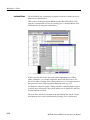
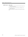
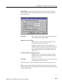
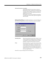
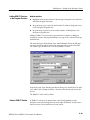
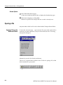
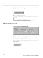
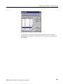
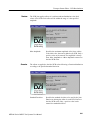
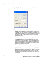
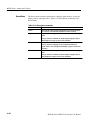
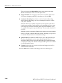
Enabling a Syntax Checking Option. To open the Analysis Settings dialog box
select Settings... from the Analysis menu.
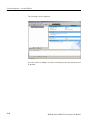
Select the Options tab. The dialog shown below is displayed:
In the Analysis Settings dialog box, the left window shows a tree structure of the
test protocols available. The right window shows the options currently allocated
to the test protocol; note that currently, options are only applicable to DSM-CC
Sections and U-U Object Carousels. Available options are applicable to all
standards, for example, an option set in the DVB DSM-CC Section will be
applied in the MPEG and ARIB protocols.
6- 10
MTS400 Series MPEG Test Systems User Manual
Carousel Analyzer - Getting Started
Opening a Stream File
Any Transport Stream file can be opened for browsing by the Carousel Analyzer.
However, only those streams containing Data and/or Carousel Objects will
provide meaningful results. Transport Stream Analyzer should be
used for normal stream analysis. Only one file can be opened at a time.
To open a file, select File > Open.... If the required file is in the list of recently
analyzed files, then it can be opened from the list to save using the open file
dialog box.
Alternatively, use the Ctrl+O keyboard shortcut.
There is a shortcut button available on the Toolbar for opening a file, which uses
the standard file open symbol:
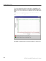
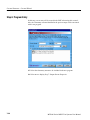
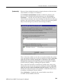
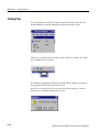
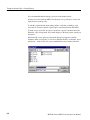
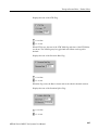
As the file opens, a progress bar is displayed; analysis may require more than
one pass through the transport stream file. The current pass number is shown in
the title line. After the first pass, a second progress bar (new resolved links)
shows the number of unresolved links at each pass.
MTS400 Series MPEG Test Systems User Manual
6- 11
Carousel Analyzer - Getting Started
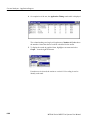
Analysis can be halted at any time by selecting the Stop button in the dialog
box; the stream is still opened, but only the elements that have been analyzed so
far will be displayed.
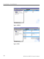
By default, the Services window and the Log window open as soon as a stream
file opens. Further windows can be opened by using the View Menu or the
Toolbar. Note that although the options on the View menu remain the same, they
are enabled or disabled according to which protocol element is highlighted at the
time.
6- 12
MTS400 Series MPEG Test Systems User Manual
Menus and Controls
The following pages contain descriptions of the menu options, toolbar controls,
status bars, and methods for managing the workspace.
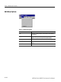
Menu Options
The following pages describe all of the menu options. Since many of the options
are context sensitive, they will be available only when their function is appropriate for the selected window or display element. When a menu option is not
available, the option is grayed out.
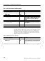
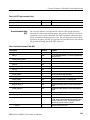
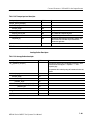
File Menu Options. Table 6--4 shows the options available in the File menu.
Table 6- 4: File menu options
Command
Function
Open...
Open an MPEG transport stream for analysis. The program
opens the file selection dialogue box allowing the user to
choose the required file.
Close
Closes the current file.
Save As...
Saves the file to a new file name.
Print
Opens the Print dialog.
Print Preview
Opens the Print Preview dialog.
Print Setup...
Opens the Print Setup dialog.
Exit
Closes any file that is open and terminates execution of the
program.
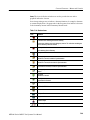
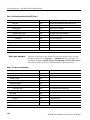
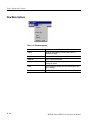
Edit Menu Options. Table 6--5 shows the options available in the Edit menu.
Table 6- 5: Edit menu options
Command
Function
Applications
Opens the Application Management dialog.
Go To Next
Jumps to next occurrence of the structure being viewed. The
Packet field in the Transport Packet bar will reflect the change
of packet.
MTS400 Series MPEG Test Systems User Manual
6- 13
Carousel Analyzer - Menus and Controls
View Menu Options. Table 6--6 shows the options available in the View menu.
NOTE. An active (depressed) button next to an option indicates that the window
or toolbar is currently visible; an inactive button means that it is hidden.
Table 6- 6: View menu options
Command
Function
Toolbars >
Submenu shows or hides the toolbar.
Transport Packet Bar
Shows or hides the Transport Packet Bar.
Status Bar
Shows or hides the Status Bar.
The remaining options in this menu open and close the associated window. The
options and windows are described elsewhere in this section.
6- 14
H
Program/Services, U-N Download, Object Carousels, Data Carousels, PIDs
and Log.
H
BIOP Message, U-N Message, Section, Transport Packet, Transport Packet
List, Hex Dump, Timing, Carrier and Resources.
H
Repitition and Bitrate.
MTS400 Series MPEG Test Systems User Manual
Carousel Analyzer - Menus and Controls
Graph Menu Options. Table 6--7 shows the options available in the Graph menu.
Table 6- 7: Graph menu options
Command
Function
Zoom
Applies to Bitrate and Repetition views only.
Zoom In: Maximizes the central 50% (x-axis) of the current
graph.
Zoom Out: Takes one step back in the Zoom sequence.
Show All: Resets the graph to show all points.
Save
Saves the graph in the selected format.
Copy
Copies the graph to the clipboard in the selected format.
MTS400 Series MPEG Test Systems User Manual
6- 15
Carousel Analyzer - Menus and Controls
Window Menu Options. Table 6--8 shows the options available in the Window
menu.
Table 6- 8: Window menu options
6- 16
Command
Function
Cascade
Rearranges the windows like this:
Tile
Tiles the windows. For example, four windows would be tiled
like this:
Arrange Icons
Aligns icons of any minimized windows at the bottom of the
program’s main window.
1 <<window title>>
2 <<window title>>
3...etc
Makes the named window active, putting it on top of any
windows that had been hiding all or part of it.
MTS400 Series MPEG Test Systems User Manual
Carousel Analyzer - Menus and Controls
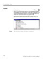
Help Menu Options. Table 6--9 shows the options available in the Help menu.
Table 6- 9: Help menu options
Command
Function
Quick Help
Opens the Quick Help browser window.
About Carousel Analyzer
Opens a message box that displays the program version
number and license number.
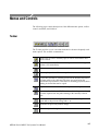
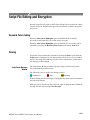
Toolbars
Quick access buttons are divided between several toolbars: File, Edit, View and
Help.
A number of the toolbar functions are context-sensitive; which window is open
and which element is highlighted will dictate which buttons are enabled and
disabled.
File Toolbar
Open a file. This button is disabled when a file is open.
Save As… - BIOP file messages can be saved to separate files.
Structures can also be saved to a separate file.
Print – only available for bit rate and repetition views.
Edit Toolbar
Jumps to next occurrence of the structure being viewed.
MTS400 Series MPEG Test Systems User Manual
6- 17
Carousel Analyzer - Menus and Controls
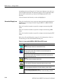
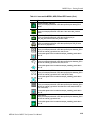
View Toolbar
The buttons in this toolbar open and close the associated windows. The windows
are described elsewhere in this manual.
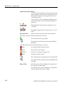
View Programs/Services
View Section
View PIDs
View Transport Packet
View Object Carousels
View Bitrate
View Data Carousels
View Repetition Rate
View U-N Download Messages
View Lifetime
View Log
Zoom In
View BIOP Message
Zoom Out
View U-N Message
Show All
Edit Application Timing
View Carousel Cycle Time
View Entity Cycle Time
View Carousel Cycle Time
Graph
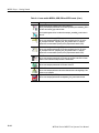
Timing Toolbar
View Entity Cycle Time
Graph
Help Toolbar
6- 18
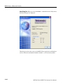
About Carousel Analyzer: Opens a dialog box which displays the
program version number and license number. This information will be
required if a Technical Support is contacted.
MTS400 Series MPEG Test Systems User Manual
Carousel Analyzer - Menus and Controls
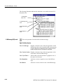
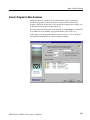
Transport Packet Bar
The Transport Packet bar provides a quick method of locating and navigating to
transport packets PIDs.
Packet:
To locate a particular Transport Packet, enter the Transport Packet number and select Goto.
PID Filter enable:
The PID navigation feature can be enabled by selecting
the checkbox (as shown).
To navigate to a specific packet: with the PID Filter disabled, enter the packet
number and select either the Previous or Next Packet button. If a PID structure
view is now requested from a View, the search for the PID will commence with
the transport packet number displayed.
Similarly, with the PID Filter enabled, each press of either the Previous/Next
button will display the previous/next transport packet containing the PID number
displayed in the PID Number field. If a PID structure view is now requested
from a View, the search for the PID will commence with the transport packet
number displayed.
NOTE. When a Transport Packet is viewed, the number in the Packet field will
increment by one.
The Transport Packet bar can be hidden from view by using the View menu
Toolbars option.
MTS400 Series MPEG Test Systems User Manual
6- 19
Carousel Analyzer - Menus and Controls
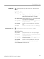
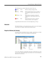
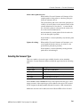
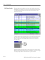
Status Bar
The Status bar provides information about the stream that is currently being
displayed. A message field gives a description of the button, menu or option that
the cursor is resting on; other non-critical messages may also be shown.
Transport packet
total
DTV analysis
standard
Message field
6- 20
Stream bit
rate
Stream
length
MTS400 Series MPEG Test Systems User Manual
Carousel Analyzer - Menus and Controls
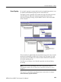
Workspace
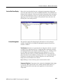
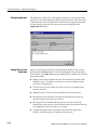
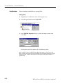
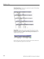
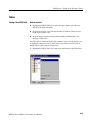
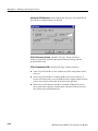
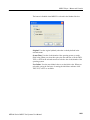
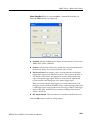
Window Management
In addition to the generic Cascade and Tile options available from the window
menu, management of individual windows is provided through a submenu
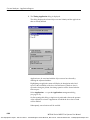
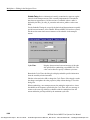
available by right-clicking the title bar of the individual window.
Right-click window title bar:
Each window within the workspace can be designated as Docked, Floating, or as
an MDI Child.
Docked. When docked, a window will be automatically placed against one of the
four sides of the workspace.
For example, selecting Docked > Top will dock the selected window at the top
of the workspace.
MTS400 Series MPEG Test Systems User Manual
6- 21
Carousel Analyzer - Menus and Controls
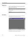
Floating. Designating a window as floating allows it to be moved around on the
monitor desktop independently of the Carousel Analyzer interface.
For example, selecting Floating will allow the window to be moved anywhere on
the desktop:
MDI Child. Designating a window as an MDI Child allows it to be moved
anywhere within the workspace.
The MDI Child submenu allows the window to be designated as Restored,
Minimized or Maximized.
NOTE. When a window is “docked” it can be dragged (and dropped) around the
workspace; when it is at an edge it will adopt a docked position. MDI Children
do not attempt to dock with the edges of the workspace.
6- 22
MTS400 Series MPEG Test Systems User Manual
Carousel Analyzer - Menus and Controls
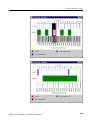
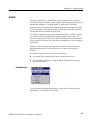
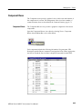
Version/Size Pane Display
Content Management
Most of the views described later use a split-pane arrangement to display the
view data and related version, file size and PID information. The information is
displayed in the right pane. However, the default arrangement when opening the
view is that the right pane is closed. To open the pane, pass the cursor over the
right edge of the view until it changes to the split pane cursor, then move the
dividing bar to the desired position.
The principles employed in displaying the information in each workspace
window are applicable to all windows, although the content will vary from
window to window.
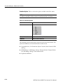
Tree Structure. Structures are represented by tree diagrams, with the “root node”
or highest level component at the top. Components that contain more information underneath them in the structure are indicated by a + box. Clicking on the +
box will display the structure underneath the node. Similarly, if a - box is
adjacent to the node, the level of detail immediately below it is already displayed; this detail can be hidden by clicking on the - box. Components that are
connected to a branch of the tree without a square box are leaf nodes; they
display the lowest and finest level of detail.
Right-clicking on a tree node may open a context sensitive menu.
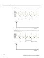
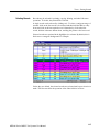
Component Selection. Components can be selected (or highlighted) either singly
or in groups. When selected, the views available from the View menu (or a
right-click menu) will be those that can be applied to all of the selected
components.
MTS400 Series MPEG Test Systems User Manual
6- 23
Carousel Analyzer - Menus and Controls
Single component selection
Selected by clicking on a component.
Range selection
Selected by highlighting the first
component in the required selection
and, while holding the Shift key on
the keyboard, clicking on the last
component. The selected range will be
highlighted.
Multiple component selection
Selected by holding the Control key
(CTRL) on the keyboard and clicking
the required components.
Node selection
Selected by holding the Alt key on the
keyboard and clicking the required
node; all subcomponents will be
selected.
6- 24
MTS400 Series MPEG Test Systems User Manual
Carousel Analyzer - Menus and Controls
Saving Components. Selected (or highlighted) components can be saved through
the right-click menu. However, the manner in which the components were
selected (see previous paragraphs) will affect the file structure of the saved
components.
If a Node Selection has been made, the directory structure is recreated at the
specified location and the subcomponents are saved to their equivalent directories.
If a Range or Multiple selection has been made, all files will be duplicated in the
root directory at the specified location in addition to recreating the directory
structure and saving the sub-components to their equivalent directories.
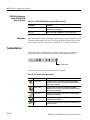
Hex Displays. Hex displays follow a common format.
The eight-digit number in the left column is the address of the first (that is, left)
byte in the row. The addresses themselves are shown in hexadecimal format.
The center column displays the contents of the structure in hex format.
The right column displays the contents of the structure in ASCII format.
MTS400 Series MPEG Test Systems User Manual
6- 25
Views
The Carousel Analyzer provides three types of view as a means of inspecting and
analyzing information carried in a transport stream.
Static Views:
(Programs/Services, Object Carousel, U-N Download, Data Carousel, PID, Log)
Static views display information derived from the transport stream when it is
opened.
Structure Views:
(Transport Packet, U-N Messages, Module, Section, BIOP Messages)
Structure views use Tektronix scripting technology to analyze structures that
appear in the transport stream, for example, tp, and BIOP messages. For repeated
structures, this view allows all occurrences to be visited.
Chart Views:
(Bitrate, Repetition Rate)
Chart views present timing information in graphical form about one or more
structure in the stream.
View
Page
View
Page
Programs/Services View
6-- 30
Structure Views
6-- 52
Object Carousel View
6-- 34
Bitrate View
6-- 55
U-N-Download View
6-- 41
Repetition View
6-- 58
Data Carousel (DVB) View
6-- 45
PID View
6-- 61
Data Carousel (ARIB) View
6-- 46
Log View
6-- 64
Resource View
6-- 50
Cycle Times View
6-- 67
In the following sections, each view is described together with the information
accessible from that view.
MTS400 Series MPEG Test Systems User Manual
6- 27
Carousel Analyzer - Views
The nodes displayed in the views relate to the protocol layers as shown in the
diagram below:
Table 6- 10: Key to Tree Nodes
6- 28
Service/Program
Active PIDs/PIDs
Download Block
BIOP Object Directory / ARIB
Directory
U-N Message
BIOP Object / ARIB Resource
Download Module
Table
Compressed Download Module
Transport Packet
Data Carousel
Audio Stream
Object Carousel
Video Stream
Stream Object
Data/Other Stream
Stream Event Object
MHP Applications
Java Application
HTML Application
MTS400 Series MPEG Test Systems User Manual
Carousel Analyzer - Views
Key to Node Overlays. Overlays are used to signify additional information about
nodes; the overlays may be used individually or in combination.
Absent Objects:
Objects referenced but not found, for example, directory object not found.
The path in which the absent object is recognized is also marked.
Unresolved Objects:
When an object is found during analysis, but its key is not referred to in the
Service Gateway, it is displayed under an Unresolved Objects node.
Boot Class Objects:
Boot class items are identified. The path in which the boot class resides is
also indicated.
Manual Signaling:
Indicates that a PID has been subjected to the manual signaling process;
used in the carousel and PID views only.
MTS400 Series MPEG Test Systems User Manual
6- 29
Carousel Analyzer - Views
Programs/Services View
Menu Bar: View > Program/Services
Toolbar:
The Programs/Services view gives a static, DVB/ARIB service (or MPEG
program) centric view of the transporst stream contents. Each program is listed
together with the service name (for DVB/ARIB). Expanding a program item will
reveal its elemental PIDs and any object (or data) carousels associated with it.
Figure 6- 2: DVB Programs/Services view (typical)
6- 30
MTS400 Series MPEG Test Systems User Manual
Carousel Analyzer - Views
Figure 6- 3: ARIB Programs/Services view (typical)
The diagram below indicates the primary nodes that are accessible from the
Program/Services view.
Service/Program node
Elementary
PID node
Table node
MTS400 Series MPEG Test Systems User Manual
See
Object/Data
Carousel View
6- 31
Carousel Analyzer - Views
Service/Program Node
This node represents a specific program or service (DVB or ARIB) in a
transport stream. If a name for the program is available in the SDT (Service
Description Table), it is displayed. Each Elementary PID listed in the PMT
(Program Map Table) will have a corresponding node displayed as a child node
of the Services/Program node. Similarly, any Object or Data Carousels associated with the Services/Program node are listed as child nodes.
Right-Click Menu Options.
Elementary PID Node
View PMT
Opens the Section Table view for the PMT.
View Bitrate
Activates or creates a bit rate view of the sum of the elementary streams that are listed in the PMT for this program.
This node represents a PID referenced by a program. If the PID
carries Sections, these are represented as Table nodes.
Right-Click Menu Options.
View Transport Packet
Displays a structure view of the next transport packet
encountered on this PID from the current stream position (as indicated by the Transport Packet number that is
displayed in the Transport Packet Bar).
6- 32
View Cycle Time "
Allows either cycle time statistics or graphical view to
be selected.
View Repetition
Activates or creates a view of the repetition rate of this
PID in the transport stream.
View Bitrate
Activates or creates a bit rate view of this PID.
MTS400 Series MPEG Test Systems User Manual
Carousel Analyzer - Views
Table Node
This node represents the stream of sections present on a specific PID with a
specific table identity.
Right-Click Menu Options.
View Section
Displays a structure view of the next section with this
PID and table identity that can be formed from the current stream position onwards (as indicated by the Transport Packet number displayed in the Transport Packet
Bar).
View Cycle Time "
Allows either cycle time statistics or graphical view to
be selected.
View Repetition
Activates or creates a view of the repetition rate of this
PID with this PID and table identity.
View Bitrate
Activates or creates a bit rate view of sections with this
PID and table identity.
MTS400 Series MPEG Test Systems User Manual
6- 33
Carousel Analyzer - Views
Object Carousel View
Menu Bar: View > Object Carousels
Toolbar:
The Object Carousel view shows a static view of every object carousel in the
transport stream.
The view is in the style of Windows Explorer. The left pane shows the directory
structure of the object carousels, and the right pane lists the versions of the BIOP
message currently selected in the left pane.
Double-clicking a file BIOP message can bring up an appropriate viewer
application if the operating system can find one (file associations can be set
through the Windows Explorer Options). File BIOP messages can also be saved
to disk by selecting File > Save As....
NOTE. The version number of the BIOP messages represents the version number
of the module that carries the BIOP message.
6- 34
MTS400 Series MPEG Test Systems User Manual
Carousel Analyzer - Views
The following diagram indicates the nodes accessible from the Object Carousels
view:
Object Carousel node
BIOP Message node
Object Carousel node
This node indicates that an object carousel has been signaled in the PSI/SI.
Right-Click Menu Options.
View Application Timing
Opens the Application Management dialog.
View DSI Carrying Carousel IOR
Displays a structure view showing the U-N DSI message
that carries the service gateway IOR for this carousel.
BIOP Message node
This node represents a specific BIOP Message. If the node represents a
BIOP directory, the directory entries appear as child nodes.
Right-Click Menu Options.
Open
View the message in its native format. This only works
for file messages that have an associated viewer application on the PC.
Save As…
Save the BIOP message to a separate file.
View BIOP Message
Displays a structure view of the next appearance of this
BIOP message that can be formed from the current
stream position onwards (as indicated by the Transport
Packet number displayed in the Transport Packet Bar).
MTS400 Series MPEG Test Systems User Manual
6- 35
Test Equipment Depot - 800.517.8431 - 99 Washington Street Melrose, MA 02176 - FAX 781.665.0780 - TestEquipmentDepot.com
Carousel Analyzer - Views
View Carrier Module Activates or creates the U-N download view and highlights the module that carries this BIOP message.
View Cycle Time "
Allows either cycle time statistics or graphical view of
the carousel to be selected.
View Repetition
Activates or creates a view of the repetition of this BIOP
message.
View Bitrate
> This BIOP message: Activates or creates a view of
the bit rate of this BIOP message.
> Including nested messages: View the sum of the bit
rates for this BIOP message and all descendant messages
(that is, all children and their children). These options
are only available for BIOP directory messages.
NOTE. If a Service Gateway is viewed in the Bitrate, Repetition, or Structure
view, its name in these views reflects the DSI transaction ID and PID in which it
was carried.
6- 36
MTS400 Series MPEG Test Systems User Manual
Carousel Analyzer - Views
MHP Applications
Unresolved Objects
(See MHP Support, page 6--91.)
When an object is found during analysis, but its key is not referred to in the
Service Gateway, it is displayed under an Unresolved Objects node.
However, when a directory object is found, the keys of its child nodes can be
resolved and its tree structure built correctly, even though the directory object
itself may still be unresolved.
MTS400 Series MPEG Test Systems User Manual
6- 37
Carousel Analyzer - Views
Absent Objects
6- 38
Objects referenced but not found are identified, for example,
- directory
object not found. The path in which the absent object is recognized is also
marked ( ).
MTS400 Series MPEG Test Systems User Manual
Carousel Analyzer - Views
Manual Signaling
If a carousel is present in a stream, but has not been found during analysis, it can
be identified with Manual Signaling from the related PID node.
The Signal Carousel command can be found on the right-click menu associated
with each PID node. When this command is selected, the stream will be
reprocessed. During processing, only the DSM-CC tables on the selected PID
will be analyzed.
The user interface is updated when the stream has been processed. Any carousels
that have been identified are added to the Carousel view. The signal icon, used
inly in the carousel and PID views, indicates that the PID has been subjected to
the manual signaling process.
The PID view will display a list of the table types that were detected during
processing.
NOTE. Carousels that span multiple PIDs will be only partially analyzed.
The PID must contain a Service Gateway for any Object Carousel view to be
displayed.
The Log view is refreshed by describing the most recent action, for example,
Added Manually Signalled PID150….
MTS400 Series MPEG Test Systems User Manual
6- 39
Carousel Analyzer - Views
Any feedback from the Manual Signaling will be displayed in the Summary log.
6- 40
MTS400 Series MPEG Test Systems User Manual
Carousel Analyzer - Views
U-N-Download View
Menu Bar: View > U-N-Download
Toolbar:
This static view shows all the U-N-download (DSM-CC data carousel scenario)
messages in the transport stream.
The view is in the style of Windows Explorer. The left pane contains a hierarchical pane on the left and a version pane on the right. The version pane will list the
versions of the U-N download message selected in the left pane.
DII items contain module items that the DII message references. All modules are
also listed under the “Modules” item.
Modules may be in compressed form; the version of the compressed icon is
displayed in the Version column of the right pane.
Modules are listed independently of DII messages in case the DII does not
reference the module correctly; for a compliant stream, each module is listed as a
child of the DII node and within the Modules node.
MTS400 Series MPEG Test Systems User Manual
6- 41
Carousel Analyzer - Views
The following illustration indicates the nodes that are accessible from the U-N
Download view.
U--N Message
(DSI) node
U--N Message (DII)
node
Download Module
node
Download Block
node
U-N Message (DSI) node
This node represents a Download Server Initiate message.
Right-Click Menu Options.
View U-N Message
Displays a structure view of the next appearance of this
DSI message that can be formed from the current stream
position onwards (as indicated by the Transport Packet
number displayed in the Transport Packet Bar).
View Carrier Section Displays a structure view of the next appearance of the
section that carries this DSI message.
6- 42
View Cycle Time >
Allows either cycle time statistics or graphical view of
the object to be selected.
View Repetition
Activates or creates a repetition view of the DSI message.
View Bitrate
Activates or creates a bit rate view of the DSI message.
MTS400 Series MPEG Test Systems User Manual
Carousel Analyzer - Views
U-N Message (DII) node
This node represents a Download Information Indication message. A DII
message may reference modules. If the module reference can be resolved, the DII
tree node will contain child Module nodes.
Right-Click Menu Options.
View U-N Message
Displays a structure view of the next appearance of this
DII message that can be formed from the current stream
position onwards (as indicated by the Transport Packet
number displayed in the Transport Packet Bar).
View Carrier Section Displays a structure view of the next appearance of the
section that carries this DII message.
Download Module node
View Cycle Time >
Allows either cycle time statistics or graphical view of
the object to be selected.
View Repetition
Activates or creates a repetition view of the DII message.
View Bitrate
Activates or creates a bit rate view of the DII message.
This node represents a U-N Download Module. The download blocks
that constitute the module are listed as child nodes.
Right-Click Menu Options.
View Hex Dump
Displays a data view of the next appearance of this module that can be formed from the current stream position
onwards (as indicated by the Transport Packet number
displayed in the Transport Packet Bar).
View Cycle Time >
Allows either cycle time statistics or graphical view of
the object to be selected.
View Repetition
Activates or creates a repetition view of the module.
View Bitrate
Activates or creates a bit rate view of the module.
MTS400 Series MPEG Test Systems User Manual
6- 43
Carousel Analyzer - Views
Block node
This node represents a U-N Download Data Block (DDB).
Right-Click Menu Options.
View U-N Message
Displays a structure view of the next appearance of this
DDB message that can be formed from the current
stream position onwards (as indicated by the Transport
Packet number displayed in the Transport Packet Bar).
View Carrier Section Displays a structure view of the next appearance of the
section that carries this DDB message.
6- 44
View Cycle Time >
Allows either cycle time statistics or graphical view of
the object to be selected.
View Repetition
Activates or creates a repetition view of the DDB message.
View Bitrate
Activates or creates a bit rate view of the DDB message.
MTS400 Series MPEG Test Systems User Manual
Carousel Analyzer - Views
Data Carousel (DVB) View
Menu Bar: View > Data Carousel
Toolbar:
This static view shows all the data carousels in the DVB transport stream. The
view is in the explorer style with a hierarchical view in the left pane and a
version view in the right.
MTS400 Series MPEG Test Systems User Manual
6- 45
Carousel Analyzer - Views
Data Carousel (ARIB) View
Menu Bar: View > Data Carousel
Toolbar:
This static view shows all the data carousels in the ARIB transport stream. The
view is in the explorer style with a hierarchical view in the left pane and a
version view in the right.
The diagram below indicates the nodes that are accessible from the Data
Carousel (ARIB) view.
Carousel node
Download Module
node
Resource node
6- 46
MTS400 Series MPEG Test Systems User Manual
Carousel Analyzer - Views
Carousel node
This node represents a single Data Carousel in the ARIB data carousel
structure.
Right-Click Menu Options.
View U-N Message
Displays a structure view of the next appearance of this
DII message that can be formed from the current stream
position onwards (as indicated by the Transport Packet
number displayed in the Transport Packet Bar).
View Carrier Section Displays a structure view of the next appearance of the
section that carries this DII message.
Download Module node
View Cycle Time >
Allows either cycle time statistics or graphical view of
the object to be selected.
View Repetition
Activates or creates a repetition view of the DII message.
View Bitrate
Activates or creates a bit rate view of the DII message.
This node contains all of the resources available to a module.
Right-Click Menu Options.
View Resources
Displays the Resource view of the selected module.
Save Resources
Saves the resource files to a selected location. The header information is not saved.
View Cycle Time >
Allows either cycle time statistics or graphical view of
the object to be selected.
View Repetition
Activates or creates a repetition view of the module.
View Bitrate
Activates or creates a bit rate view of the module.
(See also ARIB Module Versions, page 6--49.)
MTS400 Series MPEG Test Systems User Manual
6- 47
Carousel Analyzer - Views
Resource node
Each Resource node is a leaf node containing one resource file.
Right-Click Menu Options.
6- 48
Open
Opens the resource in an associated application to allow
it to be viewed. If no association has been made with the
file type on the host computer, a message is displayed.
Save
Saves the resource file to a selected location. The header
information is not saved.
View
Displays the Resource view. The selected resource is
highlighted in the Resource view.
MTS400 Series MPEG Test Systems User Manual
Carousel Analyzer - Views
ARIB Module Versions
Note that there may be multiple versions of a single ARIB module. Each version
of the same module can potentially contain different resources. For example,
Version 1 may contain resources A, B, and C and Version 2 may contain
resources C, D, and E.
When viewing the resources in Data Carousel and Service/Program views, the
resources listed under the Module node will be all resources across all versions,
for example, A, B, C, D and E. When opening or saving any of these resources
from Data Carousel or Service/Program views, the operation will work on the
first version encountered in the stream (A, B, and C will come from Version 1
and D and E will come from Version 2). Basically, these two views contain a
summary of all the resources encountered in that module regardless of version.
The ARIB Resource view will show only the resources contained in an
individual module version - to view resources from different module versions,
the user must use the Go To Next command or open a different version in ARIB
Resource view.
MTS400 Series MPEG Test Systems User Manual
6- 49
Carousel Analyzer - Views
Resource View
Menu Bar: View > Resources
The ARIB Resources view displays a hierarchical and raw data interpretation of
the resource structure in Data Carousels. The raw data is presented in hexadecimal and ASCII form in the adjacent pane.
Resources
node
Resource
node
Data
Resources node
This Resources node displays a header and the resources associated with
one Module.
Right-Click Menu Options.
Go To Next
Save
6- 50
Displays the next occurrence of the Resource node in the
transport stream (note the change of Packet number in
the Status bar).
Saves the resource files to a selected location. The header information is not saved.
MTS400 Series MPEG Test Systems User Manual
Carousel Analyzer - Views
Resource node
Each Resource node displays header information and a resource.
Right-Click Menu Options.
Data
Open
Opens the resource in an associated application to allow
it to be viewed. If no association has been made with the
file type on the host computer, a message is displayed.
Save
Saves the resource file to a selected location. The header
information is not saved.
Represents the currently selected tree node.
Right-Click Menu Options.
Save As…
Saves the Module Resource data to a selected location.
Go To Next
Displays the next occurrence of the Resource node in the
transport stream (Note the change of Packet number in
the Status bar).
View Transport Packet List
Displays the Transport Packet Contributions view
which lists the transport packets that have contributed to
the resources in the module (See Structure Views,
page 6--52).
MTS400 Series MPEG Test Systems User Manual
6- 51
Carousel Analyzer - Views
Structure Views
Structure views display a hierarchical and raw data interpretation of a structure
(BIOP Message, U-N Message, Module, Section, or Transport Packet). The
hierarchical view is based on a script from the script files that are loaded (see
Script Selection and Manipulation, page 6--6). Raw data is presented in
hexadecimal and ASCII format in the lower pane.
Highlighting an element in the table window will automatically highlight the
section of the hexadecimal code that contains the selected information.
The view will bring up the first appearance of a particular message in the
transport stream reading from the current packet position. To view the next
appearance, select Edit > Go to Next. This will display the next repetition of the
message in the open structure view window; if necessary, it will wrap to the first
occurrence.
For example, in the screenshot below, the PAT first appears in transport packet 0.
Selecting Go to Next and viewing the section again will show the next repetition
of the PAT on transport packet 532 and so on.
6- 52
MTS400 Series MPEG Test Systems User Manual
Carousel Analyzer - Views
Since the structure view is based on a script, the script can be edited and the
presentation of the packet or message changed.
Right-clicking on the any item in the structure view will open this menu:
Using the Save As… option, the structure can be saved to a separate file.
The Go To Next option moves the structure view to the next repetition of the
same item. If the current view is the last in the stream, the option will loop back
to the first repetition in the stream.
MTS400 Series MPEG Test Systems User Manual
6- 53
Carousel Analyzer - Views
The information displayed by the structure view may be carried in one or more
transport packets. By right-clicking the item and selecting View Transport
Packet List, a list of the transport packets carrying the information will be
displayed. Highlighting a Packet Number and selecting View will display the
selected transport packet structure. Several structure views can be opened in this
way but the views are not enabled until the Transport Packet Contributions
dialog is closed.
The Low and High Index entries in the Transport Packet Contributions dialog
box indicate the first and last byte respectively of the packet that contributes to
the structure.
The screenshots below illustrate an example of this sequence of actions:
6- 54
MTS400 Series MPEG Test Systems User Manual
Carousel Analyzer - Views
Bitrate View
Menu Bar: View > Bitrate
Toolbar:
This structure view charts the bit rate of a set of transport entities (for example,
BIOP message, PID, module). The bit rate calculation is a rolling average. For
any transport entity the sum of the transport packets that contribute to that entity
in each 100 ms time-slice are summed. The average is calculated every 100 ms
using the last 10 time-slices (that is, the bit rate is the average over the last
second).
In some cases a choice is offered between displaying the bit rate of the selected
element or a composite bit rate of the selected element and its subsidiary (nested)
elements.
NOTE. In calculating bit rates, Carousel Analyzer returns to the stream file. For
large files, the calculation may take an appreciable amount of time.
MTS400 Series MPEG Test Systems User Manual
6- 55
Carousel Analyzer - Views
The y-axis is automatically scaled to accommodate the maximum bit rate. The
name of the element from which the bit rate is derived and the related graph are
linked by color; a line (of the same color) is displayed to the right of the element
name.
If the bit rate for a second element is requested, it is displayed on the same
graph, as shown in the following illustration:
Any number of element bit rates can be displayed; each will be a separate color.
6- 56
MTS400 Series MPEG Test Systems User Manual
Carousel Analyzer - Views
Inspecting Bitrates
It is possible to zoom in on an area of the graph in order to inspect the bit rate in
detail.
To zoom in on the central 50% of the displayed graph, use the Graph > Zoom
> Zoom In menu option (or the Toolbar button:
be repeated.
; or tab key). This action can
To zoom in on any area of the bit rate graph, drag the mouse while holding the
left-button, to highlight the area required. When the mouse button is released, the
highlighted area will be enlarged to fill the graph area.
The menu option Graph > Zoom > Zoom Out (Toolbar:
; or shift-tab key)
will zoom out one step at a time; a step being the previous zoom in actions.
The menu option Graph > Zoom > Show All (Toolbar:
graph with no zoom factor applied.
Saving/Copying
) will redisplay the
The graph can be saved or copied in text format or as a picture file (JPEG or
bitmap).
Menu Option
Description
Graph > Save
Save the graph to a user defined location.
> Bitmap
Size the graph window before saving.
> JPEG
Size the graph window before saving.
> Table
Tab delimited format.
Graph > Copy
Copy to clipboard, from where it can be pasted into a suitable
application:
> Image
> Table
MTS400 Series MPEG Test Systems User Manual
Tab delimited format.
6- 57
Carousel Analyzer - Views
Repetition View
Menu Bar: View > Repetition
Toolbar:
This structure view charts the repetition of a set of data broadcast entities. This
Gantt style graph displays a row for each transport entity (for example, BIOP
message, U-N message etc) selected. A colored block on the row indicates the
presence of the message at that point in the transport stream.
NOTE. In calculating repetition rates, Carousel Analyzer returns to the stream
file. For large files, the calculation may take an appreciable amount of time.
Inspecting Repetition
Rates
It is possible to zoom in on an area of the graph in order to inspect the repetition
rate in detail.
To zoom in on the central 50% of the displayed graph, use the View > Zoom >
Zoom In menu option (or the Toolbar button). This action can be repeated.
To zoom in on any area of the repetition rate graph, drag the mouse while
holding the left-button, to highlight the area required. When the mouse button is
released, the highlighted area will be enlarged to fill the graph area.
6- 58
MTS400 Series MPEG Test Systems User Manual
Carousel Analyzer - Views
MTS400 Series MPEG Test Systems User Manual
6- 59
Carousel Analyzer - Views
or shift-tab key)
The View > Zoom > Zoom Out menu option (Toolbar:
will zoom out one step at a time; a step being the previous zoom in actions.
The View > Zoom > Show All menu option (Toolbar:
graph with no zoom factor applied.
) will redisplay the
Tooltips: When the cursor is placed over a block, a tooltip provides the PID,
time, and packet number.
Saving/Copying
6- 60
The graph can be saved or copied in text format or as a picture file (JPEG or
bitmap).
Menu Option
Description
Graph > Save
Save the graph to a user defined location.
> Bitmap
Size the graph window before saving.
> JPEG
Size the graph window before saving.
> Table
Tab delimited format.
Graph > Copy
Copy to clipboard, from where it can be pasted into a suitable
application.
> Image
Copy image.
> Table
Tab delimited format.
MTS400 Series MPEG Test Systems User Manual
Carousel Analyzer - Views
PID View
Menu Bar: View > PIDs
Toolbar:
This static view displays all the active PIDs within the transport stream. A PID
carrying sections will have nested items, which detail the table types on that PID.
The structure, bit rate, and repetition of transport packets and sections are
available from this view.
The following diagram indicates the nodes accessible from the PIDs view.
Active PIDs node
PID node
Table node
MTS400 Series MPEG Test Systems User Manual
6- 61
Carousel Analyzer - Views
Active PIDs node
This node represents all the PIDs found in the current transport stream; the
PIDs are listed as child items.
Right-Click Menu Options.
View Transport Packet
Displays a structure view of the packet at the current
stream position (as indicated by the Transport Packet
number displayed in the Transport Packet Bar).
PID node
Represents all the transport packets with a particular PID. If the PID carries
sections then the PID tree node will have child table tree nodes.
Right-Click Menu Options.
View Transport Packet
Displays a structure view of the next transport packet
encountered on this PID from the current stream position (as indicated by the Transport Packet number displayed in the Transport Packet Bar).
6- 62
View Cycle Time >
Allows either cycle time statistics or graphical view to
be selected.
View Repetition
Activates or creates a view of the repetition of this PID
in the transport stream.
View Bitrate
Activates or creates a view of the bit rate of this PID.
MTS400 Series MPEG Test Systems User Manual
Carousel Analyzer - Views
Table node
This node represents the stream of sections present on a specific PID with a
specific table identity.
Right-Click Menu Options.
View Section
Displays a structure view of the next section with this
PID and table identity that can be formed from the current stream position onwards (as indicated by the Transport Packet number displayed in the Transport Packet
Bar).
View Cycle Time >
Allows either cycle time statistics or graphical view to
be selected.
View Repetition
Activates or creates a view of the repetition rate of this
PID with this PID and table identity.
View Bitrate
Activates or creates a bit rate view of sections with this
PID and table identity.
Signal Carousel
(See Manual Signaling, page 6--39.)
MTS400 Series MPEG Test Systems User Manual
6- 63
Carousel Analyzer - Views
Log View
Menu Bar: View > Log
Toolbar:
The log view is a tabbed window with each tab representing information about a
particular MPEG-2 layer. Each tab contains any miscellaneous information about
the transport stream that has been analyzed. For example, packets that have the
transport_error_bit set will have an entry in the transport log tab.
The diagram below indicates the information that is accessible from the Log
view.
Summary
6- 64
This view provides a summary of the transport stream analysis.
MTS400 Series MPEG Test Systems User Manual
Carousel Analyzer - Views
Transport Packet Log view
This view displays the errors that have been logged in transport packets
during analysis of the stream.
Right-Click Menu Options.
View Transport Packet
MTS400 Series MPEG Test Systems User Manual
Displays a structure view of the highlighted
transport packet.
6- 65
Carousel Analyzer - Views
Section Log view
This view displays the errors that have been logged in sections during
analysis of the stream.
Right-Click Menu Options.
View Section
DSM-CC Section Log view
Displays a view of the highlighted section.
This view displays the errors that have been logged in DSM-CC sections during
analysis of the stream.
Right-Click Menu Options.
View Section
U-U Object Carousel
6- 66
Displays a view of the highlighted DSM-CC section.
This view displays the warnings that have been logged in U-U Object sections
during analysis of the stream.
MTS400 Series MPEG Test Systems User Manual
Carousel Analyzer - Views
Cycle Times View
Cycle times can be calculated for either a carousel (given a starting point) or an
entity in the transport stream.
In the following diagram, a carousel is shown carrying objects A, B and C.
In this example, object B is identified as the starting point for both carousel and
entity cycle timing. The cycle time of a carousel is the time taken to receive all
of the objects within the carousel given a specified starting point in the carousel.
The cycle time of any given entity in the transport stream (including Section,
BIOP Object, PID and U-N Message) is the time taken from the start of an
instance to the start of the next instance.
The cycle times calculated give the maximum, minimum and mean times for the
occurrences of an object in a transport stream in seconds; standard deviation and
number of cycles found will also be displayed. The statistics can also displayed
in graphical format.
MTS400 Series MPEG Test Systems User Manual
6- 67
Carousel Analyzer - Views
Carousel Cycle Times
Statistics
The cycle time of an object carousel is the time taken for all components of the
carousel to be received starting with a selected component of the carousel.
Selecting one or more BIOP objects from a carousel and View Carousel Cycle
Time from the right-click menu generates the Carousel Cycle Times statistics
window. The information can also be displayed in graphical form by selecting
View Carousel Cycle Time Graph.
In the Carousel Cycle Times window, the BIOP Object column identifies the
PID, Carousel ID and Object that the user identified as a starting point for the
test.
The information can also be displayed in graphical form.
6- 68
MTS400 Series MPEG Test Systems User Manual
Carousel Analyzer - Views
Entity Cycle Times
Statistics
Similarly, the cycle time of any entity (object) in the transport stream is the time
between the start of an instance of the entity and the start of the next instance.
Selecting one or more entities in any view and View Entity Cycle Time from
the right-click menu generates the Entity Cycle Times statistics window. The
information can also be displayed in graphical form by selecting View Entity
Cycle Time Graph.
The Entity column identifies the PID, Carousel ID and Object that the user
identified as a starting point for the test.
In both Carousel and Entity statistics windows, further cycle time statistics will
be added to the bottom of the list while the window remains active.
Similarly, with one or more entries in a Cycle Times window selected, the
right-click menu allows the user to display a graph of the cycle times or export
cycle time statistics to a text file.
MTS400 Series MPEG Test Systems User Manual
6- 69
Application Support
Carousel Analyzer provides a means of testing the effects of associating
applications with Object Carousels. An application consists of a “boot class” and
“assets”. Typically, a boot class will comprise a Java or HTML class; assets may
be images or text required by the boot class.
A comprehensive range of tests and measurements is provided in addition to
application management tools.
A single Object Carousel may be timed with several applications in the Carousel
Analyzer.
Application Management
The Application management dialog shows the applications currently defined
and allows the user to manage them. The user can also create new applications.
When defining an application, it may be done by adding application tree nodes
manually using context menus, or by moving parts of currently available object
carousels over to the application. It is also possible to move over sub-trees from
the hard disk to the application definition.
If an asset is specified as a wildcard, the timing will wait for that asset and all
child assets that are found in the transport stream. This means that a directory
can be specified as a wildcard asset and any content found underneath it in the
transport stream will be treated as an asset, for example, specify \bin\startup.class as the boot class, and \images\ as a wildcard directory asset. Any
content in the \images\ directory in the carousel will be treated as an asset.
MTS400 Series MPEG Test Systems User Manual
6- 71
Carousel Analyzer - Application Support
To open the Applications management dialog, select Edit > Applications....
The following dialog box is displayed:
In the Applications management dialog, the main list displays those applications
that have already been created. Application data is stored locally in the file
C:\Program Files\Tektronix\DataTestSystem\applications.dat; this is the
installation directory but it may have been modified by the user. This data file
can be copied to other Carousel Analyzer installations if required.
A summary of the highlighted application is displayed below the list; the user
should enter this summary when the application is created.
The dialog button functions are described as follows:
6- 72
New
Allows a new application to be defined in the New Application Definition dialog box.
Keyboard shortcut: Insert.
Copy
Creates a copy of the highlighted application. The new
application is allocated a modified name (Copy of …).
Edit…
Allows the highlighted application to be edited in the
Edit Application Definition dialog box.
Shortcut: Double-click application name.
Rename…
Allows the highlighted application to be renamed.
Keyboard shortcut: F2.
Delete
Deletes the highlighted application after receiving confirmation from the user.
Keyboard shortcut: Delete.
MTS400 Series MPEG Test Systems User Manual
Carousel Analyzer - Application Support
Auto Create
Creates an application definition for each MHP application that is found in the stream. The boot class for each
application is also set up.
Select OK to close the dialog box. All of the buttons, except New, are disabled
unless an application is highlighted; New is always enabled.
Application Definition
Applications are defined using the New Application Definition dialog as shown
in the following illustration:
(Initially the Application panes will be empty except for the root nodes (Boot
Class and Assets)).
MTS400 Series MPEG Test Systems User Manual
6- 73
Carousel Analyzer - Application Support
The elements of the New Application Definition dialog box are as follows:
Object Carousels tab: This displays all of the object carousels in the current
transport stream. Note that if the current transport stream
carries no object carousels, then none will be displayed
here.
The example screenshot below shows the Object Carousels displayed in the New Application Definition dialog
box overlaid onto the standard Object Carousel views.
Name
Enter the name of the application.
Description
An optional field that allows a brief description of the
application to be entered.
The boot class and the assets are displayed as parts of a tree structure in the
lower pane. The boot class is the object that must be loaded first in an application (an executable image). Assets are data objects to be used by the Boot Class
in the same carousel (for example, picture files, and text files).
6- 74
MTS400 Series MPEG Test Systems User Manual
Carousel Analyzer - Application Support
Selecting the OK button closes the dialog box and stores the new application
data. The action will be refused if a boot class object has not been specified. If a
duplicate application name has been entered, it must be renamed.
The boot class must be in the associated carousel; if it is not, the timing test
cannot be performed. An asset is a BIOP object in the carousel that is used by
the boot class. If the asset is not in the associated carousel, the user will be
warned that the assets could not be found and the tests will be performed as if
those assets had not been defined.
Selecting the Cancel button closes the dialog and discards the new application
data.
MTS400 Series MPEG Test Systems User Manual
6- 75
Carousel Analyzer - Application Support
Testing an Application
The Test button at the bottom of the application dialog box allows items in the
application to be tested against the currently selected carousel. This can be used
to ensure that the correct carousel has been selected for the application and that
all of the objects are present. The results of the test are displayed in the
Application Test dialog.
Adding Objects to the
Application
Objects are moved from the Object Carousel pane to the Boot Class or Asset
panes using the Add Asset button. T do this, highlight the object in the Object
Carousel pane, select Add Asset, and note that the object is added to the adjacent
application structure.
6- 76
H
Making a node that has children an asset will automatically include all the
children as assets. To include every object in a carousel, add the carousel
root node to the application.
H
The boot class can only contain one object; it may be at any depth in the
directory structure.
H
Adding an object to the Boot Class will displace any existing object.
H
Moving assets from the Object Carousel will automatically recreate the
directory structure from the object carousel.
H
Moving assets from the hard disk directory tree will only recreate the
structure below the source tree node. When moving assets from the directory
tree, highlight a node in the asset tree as a target.
H
A right-click context menu is available at all nodes in the application
structure; available options will depend on the node type.
MTS400 Series MPEG Test Systems User Manual
Carousel Analyzer - Application Support
The context menu options operate on the currently highlighted node in the
application structure as follows:
Editing an Application
Add Child
Adds a child node. It can be subsequently renamed to
indicate an object.
Rename
Allows a node to be renamed.
Delete
Deletes the node.
Toggle Wildcard
Asset directory nodes can be identified as wildcard entries. A wildcard directory indicates that the directory
and all of its children at the time of analysis are defined
as assets.
Application editing is similar to creating a new application.
MTS400 Series MPEG Test Systems User Manual
6- 77
Carousel Analyzer - Application Support
Application Timing
The Application Timing feature allows the user to observe the effect in terms of
download time of one or more applications being timed with an object carousel.
In practice, an object carousel is identified and one or more applications are
selected from the current application list to be timed with it. As each application
is selected, the software will check the availability of the Boot Class and Assets.
If the Boot Class cannot be found, the timing operation will fail. If Assets cannot
be found, the timing tests can still be performed, but they will not represent the
true effect of the application on a particular carousel.
Progress bars are displayed while the tests are being performed.
The results of the application timing tests are presented in tabular form.
6- 78
MTS400 Series MPEG Test Systems User Manual
Carousel Analyzer - Application Support
Data displayed in tabular form can be displayed in graphical form or exported to
a tab separated file.
MTS400 Series MPEG Test Systems User Manual
6- 79
Carousel Analyzer - Application Support
Explanation of Timing
Tests
This section gives a graphical explanation of each of the application timing tests.
The calculations assume that control information (DSI/DII; that is, SI/PSI
information, for example, PAT, PMT) has been cached.
The boot class must be received before any of the assets can be received. This
simulates the STB not knowing which carousel objects the boot class depends on
until it has completely received and processed it.
Best Transmission Time. From the start of a boot class to the end of the last asset.
The true application load time is the transmission time plus the time taken by the
set-top box (STB) to load the application. The time taken by the STB to load the
application is not included in these tests.
6- 80
MTS400 Series MPEG Test Systems User Manual
Carousel Analyzer - Application Support
Worst Transmission Time. From the end of a boot class, through the next boot
class, to the end of the last asset.
The true application load time is the transmission time plus the time taken by the
set-top box (STB) to load the application. The time taken by the STB to load the
application is not included in these tests.
MTS400 Series MPEG Test Systems User Manual
6- 81
Carousel Analyzer - Application Support
Cycle Time. From the start of a boot class, through the last asset, to the start of
the next boot class.
Best Boot Time. From the start of a service gateway, through the next boot class,
to the end of the last asset.
6- 82
MTS400 Series MPEG Test Systems User Manual
Carousel Analyzer - Application Support
Worst Boot Time. From the end of a service gateway, through the next service
gateway, through the next boot class, to the end of the last asset.
MTS400 Series MPEG Test Systems User Manual
6- 83
Carousel Analyzer - Application Support
Cold Boot Time. Whereas the other timing methods assume that control
information (PAT, PMT, DSM-CC section, etc.) has been cached, this method
does not.
The user defines a sampling frequency, which is timed to start the download and
observe how long it takes to signal the carousel and download the service
gateway, the boot class and all of the assets. For example, in a 60-second stream,
a Start Point (on the Cold Boot Time Settings dialog) of five seconds will
sample the download time twelve times. The result is added to the Application
Timing results table and graph.
The boot class must be received before any of the assets can be received. This
simulates the STB, not knowing which carousel objects the boot class depends
on until it has completely received and processed it.
Directories must be received before any child objects can be received in this
case. This is because this timing method assumes no signaling caching.
The end of each cycle will be the end of the module containing the last asset.
This is an important distinction because an asset may not be the only one in that
module.
6- 84
MTS400 Series MPEG Test Systems User Manual
Carousel Analyzer - Application Support
Setting up a Timing Test
It is assumed that applications have been created as described in the previous
section.
1. With the Object Carousel view active, select View > Timing > Application
Timing.
Alternatively, highlight an object carousel and select View Application
Timing from the right-click menu (not shown).
MTS400 Series MPEG Test Systems User Manual
6- 85
Carousel Analyzer - Application Support
2. The Timing Application dialog is displayed:
The dialog displays the selected object carousel identity and the applications
that are already defined.
Applications to be associated with the object carousel are selected by
enabling the adjacent checkbox.
Highlighting an application name will display its description and a brief
report on the availability of the boot class and assets. If the boot class is
reported as being not present, the timing operation will be aborted after the
first test pass.
Select Applications… to open the Applications management dialog
(see page 6--71).
On first opening this dialog, a simple test is performed to detect the presence
of the required boot classes. Applications for which the boot class is found
will be enabled.
Subsequently, user selections will be recalled.
6- 86
MTS400 Series MPEG Test Systems User Manual
Test Equipment Depot - 800.517.8431 - 99 Washington Street Melrose, MA 02176 - FAX 781.665.0780 - TestEquipmentDepot.com
Carousel Analyzer - Application Support
Treat Intermediate Directories as Assets:
If this checkbox is enabled, all directories that form part
of the asset path are also treated as assets. They must be
downloaded as part of the timing test. This will not usually have any significant impact on the results because
directories are generally much smaller and transmitted at
a higher frequency than files.
Calculate Cold Boot Time:
If this checkbox is enabled, the Cold Boot timing test
will be applied (see page 6--84); this may take some
time.
NOTE. In MHP mode, if the Cold Boot time is to include the AIT acquisition
time, the Application Timing selection must be made from an MHP application
node (Java or HTML). By selecting an MHP application, the application’s AIT
will be automatically included in the Cold Boot timing.
3. Select Go to start the timing tests.
If the Calculate cold boot time checkbox was enabled, the Cold Boot Time
Settings dialog is displayed. Enter the starting point repetition rate required.
Select OK to continue with the tests.
Progress bars will be displayed while the test is being carried out.
MTS400 Series MPEG Test Systems User Manual
6- 87
Carousel Analyzer - Application Support
4. On completion of the test, the Application Timing results table is displayed.
The column headings are largely self-explanatory. Number of Cycles shows
the number of times that the test could be calculated for the stream.
5. To display the results in graphical form, highlight a test name and select
Graph… from the right-click menu.
If another test is selected, the results are overlaid. Color coding is used to
identify each result.
6- 88
MTS400 Series MPEG Test Systems User Manual
Carousel Analyzer - Application Support
The screenshot below illustrates a graph showing all five test results (Cold
Boot not shown).
Zoom in and zoom out buttons are provided on the toolbar (or use the tab
and shift-tab keys on the keyboard).
MTS400 Series MPEG Test Systems User Manual
6- 89
Carousel Analyzer - Application Support
Alternatively a precise area can be selected by dragging the mouse over the
required range (hold the left-button, move the mouse, release the button).
When the mouse button is released, the zoomed area of the graph will be
displayed immediately (as shown below).
6- 90
MTS400 Series MPEG Test Systems User Manual
MHP Support
Although described separately here, MHP Object Carousel support is fully
integrated into Carousel Analyzer. MHP applications are displayed in the
Services and Object Carousel views. The features described here can be accessed
from menu options and right-click context menus.
The MHP application ( ) is identified by its name in the AIT. If the boot class
is found in the Service Gateway, it is attached as a child of the MHP application.
As a visual aid, boot class items are identified in the Service Gateway by green
triangles overlaying the primary icon. The path in which the boot class resides is
also indicated by green triangles.
Applications are designated as Java ( ) or HTML ( ). The color of the icon
represents the running status of the application when the carousel was recorded;
green indicates running, yellow indicates ready and red indicates not running.
MTS400 Series MPEG Test Systems User Manual
6- 91
Carousel Analyzer - MHP Support
Right-Click Menu Options
Right-click on an MHP application node to display the following menus:
View Application Timing
(See Application Timing, page 6--71)
View AIT
Opens the AIT structure view (see also Structure Views, page 6--52)
View Application Lifetime
(See Application Lifetimes, page 6--71)
6- 92
MTS400 Series MPEG Test Systems User Manual
Carousel Analyzer - MHP Support
Application Lifetimes
This Gantt style graph displays an analysis of the lifetime of an MHP application. Multiple applications can be displayed; each application is subdivided and
color-coded to indicate the changing state of the application.
The Applications Lifetimes view can be opened by highlighting an MHP
application node and selecting either the toolbar icon or View Application
Lifetime from the right-click menu.
A key to the color codes is displayed at the bottom of the view. Each application
is labeled. Placing the cursor over a color block displays details of the block,
including the block start time.
MTS400 Series MPEG Test Systems User Manual
6- 93
Reference
Script Files
The following scripts (Table 6--11) are shared between the Carousel Analyzer
They exist in the Tektronix\Scripts directory.
Table 6- 11: Script Files - General
Script file name
Purpose
MPEG.scp
Scripts for MPEG sections and descriptors.
DVB.scp
Scripts for DVB sections and descriptors.
ISDB-T.scp
Script for ISDB-T sections and descriptors.
ISDB-S.scp
Script for ISDB-S sections and descriptors.
MHP.scp
Script for AIT table.
MPE.scp
Scripts for DVB datagrams.
DSMCCv2.scp
General purpose DSMCC structures.
DSMCC.scp
Scripts for (DVB) DSM-CC sections.
ISDB_DSMCC.scp
ISDB version of the DSM-CC script.
MTS400 Series MPEG Test Systems User Manual
6- 95
Carousel Analyzer - Reference
The following scripts (Table 6--12) are used only by the Carousel Analyzer. They
exist in the Tektronix\DataTestSystem\Scripts directory.
Table 6- 12: Script Files - Carousel Analyzer
Script file name
Purpose
Transport.scp
Script for transport packets.
Pat_Cat.scp
Script for PAT and CAT sections.
Biop.scp
Scripts for BIOP messages.
DSMCC_DataCarouselObject.scp
Script for DSM-CC objects, which relate a Data
Carousel.
DSMCC_DataCarouselSection.scp
Script for DSM-CC sections, which relate a Data
Carousel.
DSMCC_ObjectCarouselObject.scp
Script for DSM-CC objects, which relate an Object
Carousel.
DSMCC_ObjectCarouselSection.scp
Script for DSM-CC sections, which relate an Object
Carousel.
DSMCC_Object
Script for DSM-CC objects, whose content is not
assumed to be either data or objects.
Error Checking
DSM-CC sections have two bit fields called section_syntax_indicator and
private_indicator (Ref 13818-6 section 9.2.2). If the section_syntax_indicator
field is 1, there is a CRC32 at the end of the section; if set to 0, there is a
checksum at the end of the section. The private_data field should always be the
complement of the section_syntax_indicator field.
If both these fields are set to the same value, the application cannot be absolutely
sure whether a CRC or a checksum is being used. It therefore attempts to use the
CRC method first and then the checksum. If neither method works, the section is
rejected.
Currently nothing will be reported in the error logs if these bits are set incorrectly. This issue will be addressed in a future release of Carousel Analyzer.
6- 96
MTS400 Series MPEG Test Systems User Manual
Carousel Analyzer - Reference
Acronyms and Abbreviations
AIT
Application Information Table
ARIB
Association of Radio Industries and Businesses
BIOP
Broadcast Inter-ORB (Object Request Broker) Protocol
DDB
Download Data Block
DII
DownloadInfoIndication message
DSI
DownloadServerInitiate message
DSM-CC
Digital Storage Media - Command and Control
DTV
Digital Television
DVB
Digital Video Broadcasting
ID
Identity
IOR
Interoperable Object Reference
JPEG
Joint Photographic Experts Group
MHP
Multimedia Home Platform
MPEG
Moving Picture Experts Group
PID
Packet IDentifier
PMT
Program Map Table
PSI
Program Specific Information
SDT
Service Description Table
SI
Service Information
U-N
User to Network
U-U
User to User
MTS400 Series MPEG Test Systems User Manual
6- 97
Carousel Analyzer - Reference
References
[1] ISO/IEC 13818-1 Information technology - Generic coding of moving
pictures and associated audio information: Systems [MPEG]
[2] ISO/IEC 13818-6 Information technology - Generic coding of moving
pictures and associated audio information - Part 6: Extension for Digital
Storage Media Command and Control [MPEG]
[3] ETS 300 468 Digital broadcasting systems for television, sound and data
services; Specification of Service Information in Digital Video Broadcasting
[DVB]
[4] EN 301 192 Specification for data broadcasting [DVB]
[5] A027 Specification for the transmission of data services in DVB bitstreams
[DVB]
[6] A047 Implementation guidelines for Data Broadcasting [DVB]
[7] SI-DAT 382 Rev.4 Implementation guidelines for data broadcasting [DVB]
[8] Digital terrestrial television MHEG5 specification [DTG]
[9] ISO/IEC 13522-5:1996(E) MHEG-5 IS [MHEG]
[10] A tutorial introduction to MHEG-5 [Authors: Strategy and Technology Ltd]
[11] ARIB STD - B24 Data Coding and Transmission Specification for Digital
Broadcasting
[12] Multimedia Home Platform, ETSI TS 101 812 v1.1.1 [DVB]
6- 98
MTS400 Series MPEG Test Systems User Manual
Carousel Generator
Getting Started
The Carousel Generator is aimed principally at the content provider user who
simply wants to create a carousel to deliver content to a set-top box quickly and
efficiently. The product also aims to support the more experienced MPEG user
who wants to modify a carousel to test the effects on equipment along the
broadcast chain. Similarly, the more experienced MPEG user can incorporate a
carousel into a transport stream alongside video and audio content.
The assembled transport stream can be saved to an MPEG file.
Data Broadcasting Overview
Data Broadcasting allows data to be transmitted in a similar way to the way in
which video and audio services are delivered to end users. Object and Data
Carousels are intended for the periodic transmission of information in a transport
stream. Data Carousels contain modules of data of unspecified content, whereas
Object Carousels contain identifiable data objects, such as JPEG files, text files
and, application software. Multimedia Home Platform (MHP) builds on object
carousels by defining parameters such as the boot class and application life cycle
in the Application Information Table (AIT).
The diagram below shows how information carried by data and object carousels
is subdivided and ultimately carried by the transport stream.
Object Carousel
:
BIOP Messages
Download Data
Carousel
:
Modules and
Blocks
DSM--CC Sections
BIOP 1
BIOP 2
BIOP 3
BIOP 4
Module 1
Block 1
Section 1
Block 2
Section 2
Block 3
Section 3
Block 4
Section 4
Block 5
Section 5
Transport Packets
Headers are
shown shaded.
BIOP messages contain a message header, a message sub-header and the
message body, which contains data. The message body may contain complete
data objects.
MTS400 Series MPEG Test Systems User Manual
7- 1
Carousel Generator - Getting Started
BIOP messages are broadcast in modules. A module is formed from one or more
concatenated, complete BIOP messages.
Each Module is fragmented into one or more Download Data Blocks that are in
turn transmitted in corresponding DSM-CC Sections.
Sections are transmitted in packets in the Transport Stream.
Carousel Generator Overview
Activity in the Carousel Generator is referred to as a “session”. During a session,
data objects are assembled into one or more carousels. Video and audio content
can also be added. Mandatory SI tables are added automatically. The structure of
the carousel can be saved in XML format; this definition file can be subsequently
reopened in a new session for further edits.
The end result of a session is the creation of a transport stream, which can be
saved to a file.
One of the main advantages of Carousel Generator is that many of the more
complex concepts in the various Object Carousel standards are hidden from the
user for the sake of clarity and user friendliness.
Three views of the assembled stream are offered: Carousels, Collections and
Programs. Each view displays aspects of the stream from a single perspective.
The three following screenshots show the same stream in each of the views.
7- 2
MTS400 Series MPEG Test Systems User Manual
Carousel Generator - Getting Started
Carousels View
The Carousels view lists the carousels and the associated objects that are
included in the session.
Carousel Types. The supported carousel types are as follows:
Object Carousels: DSMCC, DVB, DTT, MHP
Object carousels
Reference specification
DSM-CC
Digital Storage Media - Command and Control
(MPEG only)
DVB
Digital Video Broadcast
DTT
Digital Terrestrial Television
MHP
Multimedia Home Platform
The type of carousel being edited dictates the available options and user interface
elements.
MTS400 Series MPEG Test Systems User Manual
7- 3
Carousel Generator - Getting Started
Collections View
Objects associated with a carousel can be grouped together in collections. The
properties of each collection can be adjusted to give the most efficient delivery in
the transport stream.
The way that individual objects in a carousel are to be transmitted often varies.
Each object in the carousel has properties including its minimum repetition rate
(maximum cycle time) and whether it is compressed. Files that need to be
transmitted with similar properties or which are logically related can be grouped
into a module. As the DSMCC module is a limited size, the process of adding an
object to a module would require calculating whether the object would fit into
the module’s available space (possibly after compression) and if no space is
available, generating a new module and feeding this back to the user. This would
slow this aspect of the user interface down appreciably.
Consequently, the concept of a collection is used to replace the size-limited
DSMCC module, with a “module of unlimited size”. Any number of objects can
be added to a collection; during stream generation, this may translate to many
modules with the same properties.
7- 4
MTS400 Series MPEG Test Systems User Manual
Carousel Generator - Getting Started
Programs View
Carousel Definition File
In the Program view, the root is the Carousel Session (as in the other views).
Immediately below this are nodes giving access to the supported (mandatory)
SI/PSI tables and a listing of PCR PIDs. There is also an Elementary Streams
node, which lists all of the imported elementary streams included in the stream
and the Program nodes, which show the allocation of carousels and elementary
streams to programs.
The current state of the Carousel Generator session can be saved to disk at any
time during the creation process, using the carousel definition file. The format of
the saved file is standard XML and can be viewed in any XML compatible
viewer (for example, Internet Explorer 5 and up); editing the XML file directly is
not recommended.
MTS400 Series MPEG Test Systems User Manual
7- 5
Carousel Generator - Getting Started
Starting the Application
The application can be started by selecting the Carousel Generator
option from the Start > Programs menu or by double-clicking the
Carousel Generator shortcut on the desktop.
In addition, files with an XML extension have an additional option in the
right-click menu (Open with Carousel Generator). When this option is
selected, Carousel Generator opens and attempts to use the file as a Carousel
Definition file (see page 7--5).
7- 6
MTS400 Series MPEG Test Systems User Manual
Carousel Generator - Getting Started
Initial Appearance
Menu bar
Toolbar
Session window
Properties window
Log window
Status bar
The full range of options available to the Carousel Generator can be accessed by
using the Menu Bar. However, the selection of options varies during the stages of
carousel creation; unavailable options are normally grayed out. The Toolbar
provides shortcuts to the more common options.
The working area of the Carousel Generator screen contains three windows: the
Session window, the Properties window and the Log window. The Session
window and the Log window can each be either floated (moved to anywhere on
the desktop) or docked to one of the four sides of the application window. The
content of the Properties window is context-sensitive; it will provide a summary
of the properties of the node highlighted in the Session window.
A full description of the Carousel Generator screen components can be found in
the Menus and Controls, page 7--40.
MTS400 Series MPEG Test Systems User Manual
7- 7
Carousel Generator - Getting Started
Session Window. The Session window is the workspace in which carousels and
collections are built and manipulated. The window has three tabs: Carousels,
Collections and Programs. Each window displays different aspects of the current
session in the form of a tree structure.
Carousel Tab
The Carousels Session window displays all of the carousels in the current session and the directories and files
associated with each carousel. It is in this window that
carousels are built and manipulated.
Collections Tab
The Collections Session window displays the collections
associated with each carousel and the allocation of files
and directories within them.
Programs Tab
The Program session window displays the contents of
the stream from the program or service point of view.
Properties Window. The Properties window provides an immediate view of the
parameters and values associated with each node in the Carousels and Collections Session windows. The values displayed are those of the currently selected
node.
Log Window. The Log window displays errors and warnings as the carousel
building and stream generation progresses.
A full description of the Carousel Generator screen components can be found in
the Menus and Controls, page 7--23.
7- 8
MTS400 Series MPEG Test Systems User Manual
Carousel Wizard
The Carousel Wizard makes the process of creating a single carousel easier. The
carousel is added to the current session. The final step of the wizard allows a
transport stream to be created using the information in the current session.
Default parameters are provided at all stages of the wizard, but the user can
change them either in the wizard screens or subsequently in the various property
dialog boxes.
The description in this section provides an overview of the wizard and carousel
creation. Individual properties and activities are described in more detail in the
Reference section. Extensive tooltips are provided with the wizard screens. Place
the cursor over any element of a screen to reveal the tooltip.
If a carousel session is in progress, the user must decide whether a new session is
required or a new carousel is to be added to an existing session.
To start a new carousel session, select File > New Carousel Session.
Any open carousel session will be closed with an option to save.
MTS400 Series MPEG Test Systems User Manual
7- 9
Carousel Generator - Carousel Wizard
The following screen is displayed:
For a new session or adding a carousel to an existing session, the wizard can now
be invoked.
7- 10
MTS400 Series MPEG Test Systems User Manual
Carousel Generator - Carousel Wizard
Step 1: Select Carousel
1. In the work area select Carousel Wizard… or select Session > Carousel
Wizard.
Step 1: Select Carousel of the Carousel Wizard is displayed.
2. Highlight the required Carousel type.
Note that depending on the type selected, some of the subsequent wizard
screens will vary in content. The content is dictated by the carousel type
selected.
3. Select Next to display Step 2: Carousel Properties.
MTS400 Series MPEG Test Systems User Manual
7- 11
Carousel Generator - Carousel Wizard
Step 2: Carousel Properties
In Step 2, the Carousel Properties are selected. Defaults are supplied but all
properties can be edited. Properties can also be edited after the carousel has
been created from the main window.
4. Make any required adjustments to the Carousel properties.
5. Select how many times the carousel should appear in the output stream.
NOTE. When using the wizard, only a single carousel is being assembled.
However, more than one carousel may be created within a session.
The number of repetitions can be specified for each carousel. The length of the
transport stream will be dictated by the carousel that requires the longest time by
virtue of its size or the number of requested repetitions . Carousels in the same
session requiring less time to fulfill their size/repetition criteria will be repeated.
6. Select Next to display Step 3: Carousel Contents.
7- 12
MTS400 Series MPEG Test Systems User Manual
Carousel Generator - Carousel Wizard
Step 3: Carousel Contents
Files and directories containing applications and resources are added to the
carousel during this step.
The buttons on the right side of the window allow individual files or
complete directory structures to be added to highlighted nodes of the
carousel. Files and directories can also be dragged and dropped from
Windows Explorer.
Add files:
Add directories:
Files and directories can be dragged and dropped within the wizard window,
to allow final adjustments to be made.
Highlighted files and directories can be also be deleted
.
7. Build the carousel structure as required.
MTS400 Series MPEG Test Systems User Manual
7- 13
Carousel Generator - Carousel Wizard
Highlighting an object and selecting Properties from the right-click menu
allows access to the object properties.
8. Select Next to display Step 4: Collection Contents.
7- 14
MTS400 Series MPEG Test Systems User Manual
Carousel Generator - Carousel Wizard
Step 4: Collection Contents
The files added in the previous step are automatically placed in a single
default Collection (as shown above). Collections allow objects to share
transmission properties including minimum repetition rate (maximum cycle
time) and compression. This step allows the user to change the properties of
the default Collection, create new Collections, and move files between the
various collections.
9. Select
to create a new collection header.
MTS400 Series MPEG Test Systems User Manual
7- 15
Carousel Generator - Carousel Wizard
10. Highlight a collection node and select
properties.
to modify the collection’s
NOTE. If the previous wizard step is reselected (Back) and more files added or
removed, the Collection assignment is maintained for existing files and new files
are placed in the parent directory’s collection by default.
7- 16
MTS400 Series MPEG Test Systems User Manual
Carousel Generator - Carousel Wizard
To modify the collection properties, highlight the required Collection node
and select Properties from the right-click menu.
11. Select Next to display Step 5: Imported Elementary Streams.
MTS400 Series MPEG Test Systems User Manual
7- 17
Carousel Generator - Carousel Wizard
Step 5: Imported Elementary Streams
In addition to the carousel objects, elementary streams from a transport stream
can be included in the session.
12. Use the Source File:
button to identify and select the transport stream.
The contents of the source file are displayed.
13. Select one or more elements from this tree to import into the current session,
or select a program node to import every element contained by the program.
7- 18
MTS400 Series MPEG Test Systems User Manual
Carousel Generator - Carousel Wizard
Note that only elements from the same source program can be selected. All
elements included in the session will be included in the output stream,
whether they are referenced by a program or not.
Where possible, elementary streams will be carried on the same PID used in
the source stream; where a conflict within the session occurs, a new PID will
be automatically allocated or can be allocated manually.
14. Having identified the source stream and the individual elementary streams to
be included in the session, select Next to display Step 6: Program Entry.
MTS400 Series MPEG Test Systems User Manual
7- 19
Carousel Generator - Carousel Wizard
Step 6: Program Entry
At this step, a new entry will be created in the PMT referencing this carousel.
Also, the elementary streams identified in the previous steps can be associated
with a new program.
15. Select the elementary streams to be included in the new program.
16. Select Next to display Step 7: Output Stream Properties.
7- 20
MTS400 Series MPEG Test Systems User Manual
Carousel Generator - Carousel Wizard
Step 7: Output Stream Properties
Use this screen to specify the name and properties of the transport stream
that is to be created.
17. Enter the TS Bitrate.
18. Enter minimum duration for the output transport stream if required.
19. Enter or select (
) an Output File name.
20. Select Next to display Step 8: Congratulations.
MTS400 Series MPEG Test Systems User Manual
7- 21
Carousel Generator - Carousel Wizard
Step 8: Congratulations
The carousel is now prepared. If the option to create the transport stream is
enabled, then all carousels in the current session will be included. The
carousel created with the wizard will be added to the session screen.
21. Select Finish to exit the wizard.
7- 22
MTS400 Series MPEG Test Systems User Manual
Menus and Controls
The following pages contain descriptions of different menu options, toolbar
controls, status bar, log window, and properties window.
Menus Options
The following pages describe all of the menu options. Since many of the options
are context sensitive, they will be available only when their function is appropriate for the selected window or display element. When a menu option is not
available, the option is grayed out.
File Menu Options
Table 7- 1: File menu options
Option
Function
New Carousel Session
Opens a new carousel session. An opportunity to save the
current session is offered, if relevant.
Open Carousel Session…
Opens an existing carousel session using a saved carousel
definition file.
Save Carousel Session
Saves the current carousel session in the form of a carousel
definition file.
If the file has not been saved, an opportunity is offered to name
it.
Save Carousel Session As…
Allows the current carousel session to be named and saved in
the form of a carousel definition file.
Most Recently Used List
Lists the most recently used carousel session files. Click on a
file name to reopen it.
The number of files displayed is set in the Carousel Generator
Options dialog box (Tools > Options).
Exit
Closes the application. An opportunity is offered to save the
session if it has not been saved.
MTS400 Series MPEG Test Systems User Manual
7- 23
Carousel Generator - Menus and Controls
Edit Menu Options
Table 7- 2: Edit menu options
Option
Function
Cut
Cuts the currently highlighted item. The item is stored on the
Windows clipboard.
Copy
Copies the currently highlighted item. The item is stored on the
Windows clipboard.
Paste
Paste the item currently on the Windows clipboard.
Empty Carousel
(Carousel contents node highlighted.) Deletes the carousel
contents.
Delete Collections
(Collection node highlighted.) Deletes the selected collection
(The Collection must be empty; the contents must be moved to
another collection first).
Delete Program
(Program node highlighted.) Deletes the selected program and
the carousel(s) it contains.
View Menu Options
Table 7- 3: View menu options
7- 24
Option
Function
MHP Applications
List MHP applications where they are included in a session.
Carousels; Log; Generator
Toolbar; Player Toolbar; Status Bar
Allows the screen elements listed to be shown or hidden.
MTS400 Series MPEG Test Systems User Manual
Carousel Generator - Menus and Controls
Session Menu Options
Table 7- 4: Session menu options
Option
Function
New Program…
(Program view.) Adds a new program node.
Import Elementary
Stream(s)…
(Program view.) Allows elementary streams to be added to the
Elementary Streams node.
New Carousel
(Carousel view or Program node.) Allows a new carousel type
to be created.
Carousel Wizard
Opens the Carousel Wizard which takes the user through
carousel and stream generation step-by-step.
Carousel Properties…
Opens the Carousel Properties dialog box.
Contents
Facilitates the file activities listed below (the menu content is
context sensitive):
Empty Carousel
Empty currently highlighted carousel.
Delete Object
Deletes currently highlighted object (and dependant objects).
Add File(s)… Adds one or more files to the selected carousel.
Add Directory… Adds a directory to the selected carousel.
New Directory…
Creates a new directory at the selected node.
Move to Collection
Moves the selected objects to another collection.
HTML Application commands
Makes, Removes, and Edits HTML applications.
Java Application commands
Makes, Removes, and Edits Java applications.
These HTML and Java Application commands are only
applicable to file objects (when a file is selected).
Synchronize
Synchronizes the carousel contents with the source files.
Delete Carousel
Deletes the selected carousel.
Delete All Carousels
Deletes all carousels in the current session.
MTS400 Series MPEG Test Systems User Manual
7- 25
Carousel Generator - Menus and Controls
Player Menu Options
Table 7- 5: Player menu options
Option
Function
Stream Generation
Properties…
Opens the Stream Generation Properties dialog box.
Start Playout
Initiates output stream generation using information in the
current session.
Stop Playout
Stops output generation.
View Packets/Time
Switches between packet count and time display during
playout.
Tools Menu Options
Table 7- 6: Tools menu options
Option
Function
Launch Multiplexer
Opens the Multiplexer application.
Launch Carousel Analyzer
Opens the Carousel Analyzer application.
Launch TS Analyzer
Opens the Transport Stream Analyzer application.
Options…
Opens the Carousel Generator options dialog box. This is used
to set the basic Carousel Generator and session defaults.
Help Menu Options
Table 7- 7: Help menu options
7- 26
Option
Function
Quick Help
Opens an HTML help page containing summarized help
information.
User Guide
Opens the Carousel Generator User Guide in Adobe Acrobatt
(PDF) format.
About Carousel Generator…
Displays information about Carousel Generator, including
Software Version and Serial Number.
MTS400 Series MPEG Test Systems User Manual
Carousel Generator - Menus and Controls
Toolbars
Two toolbars can be displayed: Generator and Player. The toolbars can be shown
or hidden using the View menu or by right-clicking in the toolbar area.
Toolbars provide a set of convenient shortcuts for the more frequently used menu
options. The buttons are context-sensitive and are enabled or disabled dependent
upon the currently highlighted view or the action being performed.
Generator Toolbar
Table 7- 8: Generator toolbar icons
Icon
Function
Equivalent Menu Bar Command
Carousel wizard
Session > Carousel Wizard (Ctrl+W)
New carousel session
File > New Carousel Session (Ctrl+N)
Open carousel session
File > Open Carousel Session (Ctrl+O)
Save carousel session
File > Save Carousel Session (Ctrl+S)
Toggle workspace view
View > Carousels
Add directory
Session > Contents > Add Directory…
Add files
Session > Contents > Add Files…
New collection
(Right-click on Collection node) >
New Collection
Insert program
Session > New Program…
Synchronize carousel
Session > Synchronise…
Launch Carousel Analyzer
Tools > Launch Carousel Analyzer
Launch Multiplexer
Tools > Launch Multiplexer
Launch Transport Stream Analyzer
Tools > Launch TS Analyzer
MTS400 Series MPEG Test Systems User Manual
7- 27
Carousel Generator - Menus and Controls
Player Toolbar
Table 7- 9: Player toolbar icons
Icon
Function
Equivalent Menu Bar Command
Playout Carousel
Player > Start Playout
Stop playout
Player > Stop Playout
Player > View Packets/Time
Toggle Packet/Time display
Toolbars can be dragged off the edge of the main window into a floating pallet.
To do this, place the mouse pointer on the background inside the Toolbar, (not on
one of the buttons), hold the left button down, and drag the toolbar into the main
window area. The result is a self-contained window that looks like this:
To replace the Toolbar on the window border, drag it over the border until the
outline changes shape. It can be placed on the top, bottom, left or right edge.
The Toolbar may be hidden from view - View > Toolbar.
7- 28
MTS400 Series MPEG Test Systems User Manual
Carousel Generator - Menus and Controls
Icons. The icons in Session windows are used to provide the user with a
graphical indication of status.
Icons incorporating an arrow indicate a shortcut function; for example, elementary streams displayed in a Program node in the Programs view indicate a shortcut
to the elementary stream in the Elementary Streams node.
Table 7- 10: Session icons
Icon
Function
Collections node
Collection node containing the Service Gateway.
At least one collection must exist during any session. The collection containing the
Service Gateway cannot be deleted.
Ordinary collection node.
Not containing Service Gateway.
Compressed collection.
Directory object
Included in Carousel; Included in Synchronization.
Directory object
Included in Carousel; Not included in Synchronization.
Directory object
Not included in Carousel; Included in Synchronization.
Directory object
shared.
File object
Included in Carousel.
File object
Not included in Carousel.
PCR node
DVB SI / MPEG PSI
Table node
Transport Stream node
Program node
Carousel object
Elementary Stream - Audio
MTS400 Series MPEG Test Systems User Manual
7- 29
Carousel Generator - Menus and Controls
Table 7- 10: Session icons (Cont.)
Icon
Function
Elementary Stream - Video
Elementary Stream - Private data
Log Window
The Log Window contains three tabbed views:
H
The Summary log records information on the general activities in the
Carousel Generator.
H
The Definition File Syntax log records information on activities concerning
the definition file.
H
The TS Generation log records information during stream generation
activities.
During file loading and saving and the generation of transport streams, error
messages are routed to the appropriate Log window tab. More information about
each error can be accessed by clicking on the error entry or selecting the
Details… option from the right-click menu.
7- 30
MTS400 Series MPEG Test Systems User Manual
Carousel Generator - Menus and Controls
The following icons are used to indicate the severity of the error:
(Blue)
Event
Indicates normal processing activity.
(Gray)
Warning
Indicates that information was not available or
was invalid. The operation will often be completed.
(Yellow)
Error
Indicates that a sub-operation could not be
completed; the overall task may still be completed.
(Red)
Fatal
Indicates that a fatal error has occurred; an
activity has failed to reach completion.
A right-click menu allows the user to clear the displayed log or all logs.
Status Bar
The Status Bar displays tool-tips when the mouse pointer is over active elements
of the window, for example, toolbar buttons and menu options.
Properties Window (List Control)
In properties windows that display lists (for example, contents lists), one column
can be selected to sort the list into ascending or descending order.
To sort a list, click the key column header. If the same column needs to be sorted
in reverse order, click the header again; note that the arrow icon in the header bar
indications the sort direction.
MTS400 Series MPEG Test Systems User Manual
7- 31
Carousel Generation
This section describes the processes required to create a transport stream
containing one or more carousels. In broad terms it echoes the steps outlined in
the Wizard, but more background information is provided.
Setting Overall Carousel Generator Properties
Although not essential during every session, the general properties of the
Carousel Generator can be set using the Carousel Generator Options dialog box.
Note that settings such as the Output Filename can be overridden in the current
session; however, the settings made here will be used as the defaults in any new
session.
Select Tools > Options… to open the Carousel Generator Options dialog box.
Carousel Generator
Options
The following screens are available in this dialog box: General, New Session
Defaults and Event/Error messages. To view a screen, click the name in the left
panel.
MTS400 Series MPEG Test Systems User Manual
7- 33
Carousel Generator - Carousel Generation
General screen
7- 34
Number of items…
A list of the most recently used carousel definition files
is displayed in the File menu. Use this parameter to select how many file names should be displayed.
Range: 0 to 15
Relative Paths
The paths of source components associated with a carousel file can be stored in relative or absolute format.
Update base path…
When a carousel definition is saved to a different (new)
location, components stored with paths relative to the
original carousel definition may no longer be found at
the same (relative) location. If Yes is selected from the
drop-down list, the base path will be modified so that
the components can still be found. Select Ask to allow
the user to make a decision when the carousel definition
is saved. If No is selected, no modification will be made
to the base path; carousel components may no longer be
accessible to the definition file.
Fix relative paths…
When the base path for components referenced by a carousel definition file is changed, the existing relative
paths may not refer to the correct locations. If Yes is selected from the drop-down list, the relative paths will be
adjusted so that they are referenced correctly to the new
base path.
MTS400 Series MPEG Test Systems User Manual
Carousel Generator - Carousel Generation
New Session Defaults
screen
Regenerate…
When enabled, launching Carousel Analyzer, Transport
Analyzer or Multiplexer causes the output stream to be
regenerated using the current session properties. This
ensures that the properties that have been entered in the
Carousel Generator are the same as those shown in the
Carousel Analyzer, Transport Analyzer or Multiplexer.
Show message…
When enabled, a message will be displayed during
stream generation if an error occurs which causes the
stream generation to terminate. The error will always be
reported in the TS Generation tab of the Log window.
This screen provides default values to be used for all new sessions and consequently in the carousel definition files and generated transport streams. The
default values can originate from a template or be set individually. The values
can be overridden in individual carousel sessions.
Startup Template
Select this option and identify a file to be used as a startup template.
Any carousel session file (XML format) can be used as a
template. It can be used primarily to retain settings
which are required from session to session, for example,
network settings.
MTS400 Series MPEG Test Systems User Manual
7- 35
Carousel Generator - Carousel Generation
Startup Settings. Select the Use the following settings… option to set the session
defaults locally.
TS Bitrate:
The bit rate of the output transport stream.
Range: 0.25 Mbit/s to 90 Mbit/s
Duration:
The duration value (in seconds) available when this feature is enabled will dictate the minimum length of the
transport stream.
PSI/SI Type:
This selection will dictate the tables that are automatically created at startup.
If MPEG PSI is selected, only the PAT and PMT will
be generated. If DVB SI is selected, the mandatory DVB
tables (NIT actual, TDT, SDT actual and EIT P/F actual)
will also be generated.
Select the Warn before… checkbox to display a message when a change to the Stream Generation PSI/SI
Type property is attempted (see page 7--40).
Output Settings.
Output File:
Enter the filename to be used in generating an output
transport stream or browse to find an existing filename.
Automatically set the default values…
If at the start of a session (with no carousels defined), changes are made to the
Stream Generation Properties (see page 7--40), whether or not the changes are
saved as Carousel Generator defaults is dictated by this setting.
7- 36
MTS400 Series MPEG Test Systems User Manual
Carousel Generator - Carousel Generation
The options operate as follows:
Ask: The dialog box shown below will allow the user to choose between using
the revised settings as future defaults or to only use them for this session.
If the Always use… checkbox in the dialog box is enabled, the Automatically
set… option in this screen will be reset to concur.
No: The revised settings will not be used as future defaults.
Yes: The revised settings will be used as future defaults.
Event/Error Messages
screen
The Log view, which can be displayed as part of the main application, displays a
series of status and error messages, which advise the user of the progress of
carousel and stream generation.
MTS400 Series MPEG Test Systems User Manual
7- 37
Carousel Generator - Carousel Generation
This screen allows the user to indicate which messages should be displayed. The
Log view contains three tabbed screens: Summary, Definition File Syntax and
TS Generation. These correspond to the message categories Summary messages,
Definition File errors and TS Generation errors in this screen.
Each message category contains four levels of severity: Events, Warnings, Errors
and Fatal Errors. Individual messages that can be displayed in the Log view are
listed at each level.
Message Selection. The checkmarks associated with each message icon indicate
the reporting status of the message.
Enabled (permanent): this message type will always be reported in
the log view.
Enabled / disabled (toggle): this message type is enabled/disabled by
the user. It will only be reported in the log view when enabled.
If one or more of the subsidiary message types in a category (Events,
Warnings Errors) is disabled, this icon is displayed.
All messages in the Summary category and Fatal Error messages in all categories
are all permanently enabled; they cannot be disabled. The remaining messages in
the Carousel Definition File and Stream Generation categories can be enabled
and disabled as required by clicking on the message icon.
A brief description of a message can be displayed by clicking on the message
name.
(See also Log Window, page 7--30.)
7- 38
MTS400 Series MPEG Test Systems User Manual
Carousel Generator - Carousel Generation
Creating a Session
A session in Carousel Generator is the activity during which objects are
assembled in one or more carousels with a transport stream being the end result.
The initial activity when starting a session is to note the defaults that are already
displayed in the Stream Generation Properties screen; these are derived from the
Carousel Generator Options. If required, the values can be modified for the
current session.
The values may be changed at any time in the session; it may be useful to review
these settings at the end of a session, before the transport stream is created.
Select Player > Stream Generation Properties... to open the Stream Generation
Properties dialog box or select Edit... in the properties window or double-click
in the properties window.
MTS400 Series MPEG Test Systems User Manual
7- 39
Test Equipment Depot - 800.517.8431 - 99 Washington Street Melrose, MA 02176 - FAX 781.665.0780 - TestEquipmentDepot.com
Carousel Generator - Carousel Generation
Stream Generation
Properties
This screen provides stream generation values to be used in the current session.
TS Bitrate:
The bit rate of the output transport stream.
Range: 0.25 Mbit/s to 90 Mbit/s.
PSI/SI Type:
This selection will dictate the tables that are created in
the generated stream. If MPEG PSI is selected, only the
PAT and PMT will be present. If DVB SI is selected, the
mandatory DVB tables (NIT actual, TDT, SDT actual,
and EIT p/f actual) will also be generated.
A warning may be issued noting that SI settings may be
lost (see New Session Defaults Screen, page 7--35).
Output File:
Enter the name and path of the output file. Select to
specify a location on local or network drives.
Relative Paths in Session…
The paths of source components associated with a carousel file can be stored in relative or absolute format.
7- 40
MTS400 Series MPEG Test Systems User Manual
Carousel Generator - Carousel Generation
Allow relative paths based on
When enabled, Carousel Generator will interpret all incomplete paths as being relative to the base path specified in the adjacent text box.
The specified base path can be an absolute path (such as
c:\data) or it can be relative to the current location of the
carousel definition file. Note that if ‘.’ is entered in the
box, all relative paths are referenced to the current location of the carousel definition file.
Any automatically created paths will also be made relative to the base path, if possible.
If the checkbox is cleared (disabled), only absolute paths
will be used.
Update all existing… When enabled, Carousel Generator will attempt to convert all paths used in the session to be relative to the
specified base path (where possible).
If the checkbox is cleared (disabled), existing absolute
paths will be left unchanged.
Selecting the Carousel Type
There are a number of carousel types available from the various standards
authorities. Carousel Generator makes available the types listed in the following
table:
Carousel Type
Guiding Standard
DSMCC Object
ISO/IEC 13818-6: 1998 (MPEG)
DVB Object
DVB EN301 192 V1.2.1
DTT Object
DTG DTT Requirements for Interoperability V3.1
MHP Object
ETSI TS101 812 V1.1.2 & V1.1.1
Select Session > New Carousel and click on the required carousel type. A new
(empty) carousel of the required type will be added to the session. The carousel
will be assigned an identity number (ID) and allocated to a PID automatically.
Additional carousels can be added; successive IDs and PIDs will be allocated.
MTS400 Series MPEG Test Systems User Manual
7- 41
Carousel Generator - Carousel Generation
Modifying the Carousel Properties
The properties of individual carousel can be modified as required. A summary of
the carousel properties is displayed in the Properties window.
The contents of the carousel are displayed when the Carousel Contents node is
highlighted.
To edit individual carousel properties, in the Carousels tab of the Sessions
window and with the carousel node highlighted, select Session > Carousel
Properties... or select Edit... in the Properties window. The Carousel Properties
dialog box is displayed.
The number of screens available in the Carousel Properties dialog box is
dependent on the carousel type selected. In the following notes, screens
dedicated to only a single carousel type are identified; all other screens are
common to all types.
The Carousel Properties dialog box can display up to four screens: General PID
settings, DSI/DII settings, DTT Applications (DTT only), and MHP (MHP
only).
7- 42
MTS400 Series MPEG Test Systems User Manual
Carousel Generator - Carousel Generation
General screen
Carousel ID:
Unique carousel identity. The Carousel ID is normally generated automatically but can be changed by the
user.
Range: 0 to 4294967295
Maximum module size:
The maximum size of the modules used to carry the
carousel objects. During output stream generation, if
a module has one or more objects and does not have
enough space for the next object, a new module will
be created. If a module is empty and the object added
will exceed the maximum size, the object is still added, but no more objects will be placed in that module.
Range: 0 to 4294967295 Default: 65536
Carousel PID (DSI PID): Select the required Association Tag from the dropdown list.
During carousel creation, a default Association is
generated to carry the Carousel/DSI PID. This cannot
be removed.
Include in Output…
MTS400 Series MPEG Test Systems User Manual
This flag allows the carousel to be included in or excluded from the output stream. If the checkbox is
disabled, no reference to this carousel or its contents
will appear in the generated output stream.
7- 43
Carousel Generator - Carousel Generation
Minimum number…
PID settings screen
Enter the minimum number of times that the carousel
is to appear in the output stream; this can be repeated
for each carousel in the session. The resulting output
stream will be long enough to accommodate at least
the minimum number of repetitions requested for
each carousel.
The tree structure in the PID Settings screen shows the PID usage for the
selected carousel’s program. The DSI and DII messages carried in the carousel
use an Association tag, which allows the BIOP messages in the carousel to be
linked to a PID in the stream (see “BS ISO/IEC 13818-6:1998 Information
Technology - Generic coding of moving pictures and associated audio information - Part 6: Extensions for DSM-CC).
To place the DII and DSI messages on different Association Tags, use the
DSI/DII settings screen (see page 7--46).
During stream generation, each Association Tag specified will result in the
following:
H
An elementary stream (ES) with a stream type of 11 (DSMCC U-N
messages) and the entered PID being added to the PMT ES loop.
H
The Association Tag value will be inserted into an association_tag_descriptor inside this ES’s descriptor loop.
Highlighting any of the association nodes will display the PID associations in the
Selected PID association panel.
7- 44
MTS400 Series MPEG Test Systems User Manual
Carousel Generator - Carousel Generation
Select New Assoc... to create a new association node in the tree. The PID and
Association Tag will be automatically allocated, but they can be changed in the
Selected PID association panel.
Selected PID association
PID:
This is the PID of the elementary stream (ES) carrying
the DII and/or DSI messages.
Range: 0 to 8191 (see PID Values, page 7--45).
Association Tag:
This is the 16 bit value carried in the association_tag_descriptor which is inserted in the ES descriptor loop of the PMT signaling this carousel.
Range: 0 to 65535
Maximum bitrate…
This is the maximum bit rate allocated in the stream for
this PID. If there is not enough bandwidth to support
this rate, the actual bit rate will be less.
Range: 0.25 Mbit/s to 90 Mbit/s
PID Values. As stated, the valid range for PIDs is 0 to 8191. However, there are a
number of restrictions on the actual values that can be used, since some are
reserved or may be used in other carousels. The following table shows the
elements that can and cannot share PID values. Unless otherwise noted, “No”
indicates the entities in the row and column headers may not share a PID value
in any carousel in a single session. ’Yes’ indicates that the PID value may be
shared with other entities in the same session; unless otherwise indicated in the
Notes below.
Reserved
PCR
PMT
AIT
DSI
DII
DII
No
No
No
No
Yes (Same
as Carousel)
Yes (Same
as Carousel)
DSI
No
No
No
No
No
-
AIT
No
No
No
No
-
-
PMT
No
No
Yes
-
-
-
PCR
No
No
-
-
-
-
Reserved
No
The Reserved PIDs are PIDs 0 to 31 (0x00 to 0x1F) and the Null
PID 8191 (0x1FFF)
MTS400 Series MPEG Test Systems User Manual
7- 45
Carousel Generator - Carousel Generation
NOTE. PIDs 0 to 15 (0x0000 to 0x000F) are reserved by MPEG; PIDs 16 to 31
(0x0010-0x001F) are additionally reserved by DVB.
PMTs cannot share PIDs with anything but other PMTs. Multiple PMT sections
can be on the same PID, so, if required, every carousel could have its PMT entry
on the same PID (usually not done that way, but it can be).
The DIIs belonging to a single carousel can be on the same PID as its DSI or its
other DIIs, but not on the same PID as DSIs or DIIs belonging to other
carousels.
For example, the yes/no indicators in the PMT row/column indicate that the
value of the PID carrying a PMT may not be shared with any other entities in the
session. However, in the case of the PMT, see the above note.
DSI/DII settings screen
The tree structure in the DSI/DII Settings screen shows the DSI and DIIs that
will be generated in the stream for the selected carousel. Each DSI/DII has an
Association Tag and a cycle time, and DIIs have a user definable name.
Highlighting any of the DII nodes will display the PID associations in the
Selected DII panel.
Select New DII to create a new DII using default values. The default Association
Tag to use is decided by first checking if an existing DII uses the DSI tag. If so,
this tag is used, otherwise the tag of the first DII in the list is used.
7- 46
MTS400 Series MPEG Test Systems User Manual
Carousel Generator - Carousel Generation
Selected DII
Name:
This is a user allocated name for this DII. The name
does not appear anywhere in the generated stream, only
within the Carousel Generator.
Assoc. tag:
This is the list of all the currently defined Association
tags listed for this carousel. Assigning a different Association Tag to the DII effectively changes the PID that
the DII messages will be carried on.
(Association tags can be added from the PID Settings
screen.)
Cycle time (ms):
This option sets the time taken for this DII to be repeated. For example, DIIs referencing boot classes may
be given shorter cycle times to speed up the boot process.
Range: 1 ms to 3600 s.
To associate a collection with a DII, first create the DII, giving it a meaningful
name, set the Association tag and Cycle time of the DII and close this dialog
box. On the Collections tab of the Session window, edit the collection’s
properties to set the field Using DII to the new DII.
MTS400 Series MPEG Test Systems User Manual
7- 47
Carousel Generator - Carousel Generation
MHP
AIT PID
This is the PID that carries the Application Information
Table (AIT).
Range: 0 to 8191 (see PID Values, page 7--45).
AIT cycle time:
Set the time to be taken for the selected Carousel’s AIT
to be repeated. Default: 100 ms.
Use… Select this option to allow the AIT cycle time to
be set manually. Range: 1 ms to 3600 s.
Use old-style…
If this box is checked, the DVB-HTML application descriptor format as defined by MHP v1.0.0 (see MHP;
ETSI 101812, Version 1.1.2 and 1.1.1) will be used.
If this box is not checked, the new format as defined in
MHP v1.1.2 (see MHP; ETSI 101812, Version 1.1.2 and
1.1.1) will be used. This will cause the DVB-HTML
Application Descriptor to be properly formed and include an empty set of application IDs. To add application IDs to this descriptor, use the HTML Properties
page on the MHP File Properties dialog box.
7- 48
MTS400 Series MPEG Test Systems User Manual
Carousel Generator - Carousel Generation
DTT Applications
Application Codes. The entries in this list will be added to the data_broadcast_id_descriptor in the elementary stream descriptor loop of the PMT. This
descriptor lists the application types that can be booted from the elementary
stream with which it is associated. The Boot Priority Hint is an indication of the
application that should be booted in the case of more than one in the list being
supported. The application with the highest Boot Priority Hint, in the range 0 to
255, will be booted first.
Add
Displays the Add Application Code dialog box.
Remove
Removes the highlighted Application Code.
MTS400 Series MPEG Test Systems User Manual
7- 49
Carousel Generator - Carousel Generation
Initial Objects. The Initial Object list allows different languages to have different
boot objects. On stream generation, entries here will appear in the ServiceContextList part of the Service Gateway object.
Add
Displays the Add Initial Object dialog box.
The Application Code should correspond to a code that
is already listed in the Application Codes panel. A
Language Code can be selected from the drop-down
list. The object can be given a name in the Carousel
Object field. If objects have already been associated
with the carousel, the adjacent button will display the
contents of the carousel, from which an object can be
selected.
Remove
7- 50
Removes the highlighted Initial Object.
MTS400 Series MPEG Test Systems User Manual
Carousel Generator - Carousel Generation
Carousel Contents
Each carousel initially contains two subnodes: Carousel Contents and Service
Gateway. The carousel will eventually contain all of the objects associated with a
particular function or feature. These objects can be arranged in a hierarchy of
directories and files all displayed beneath the Service Gateway node.
Files and directories can be manipulated in a variety of ways:
H
All commands are accessible via the Menu Bar or context sensitive
right-click menus.
H
Files and directories can be dragged and dropped within Carousel Generator.
H
Files and directories can be dragged from Windows Explorer.
The properties of files and directories can be edited after they have been
incorporated into a carousel.
MTS400 Series MPEG Test Systems User Manual
7- 51
Carousel Generator - Carousel Generation
Adding an Object
(File/Directory)
Individual files or complete directory structures can be added to a carousel. New
directories can be created.
The location that an object is to be added to should be highlighted.
Adding Directories.
1. Highlight the node in the carousel where the directory is to be added.
2. Select Carousel > Contents > Add Directory…
7- 52
MTS400 Series MPEG Test Systems User Manual
Carousel Generator - Carousel Generation
The Add Directory dialog box is displayed.
The Add Directory allows the user to select any available directory. The
directory path is shown in the top field; the most recently accessed directories are available in the drop-down list. The adjacent checkboxes have the
following functions:
Add Contained Files: All files contained in the selected directory (and any
subdirectories if Add Subdirectories is enabled) will be added to the
carousel.
Add Subdirectories: All subdirectories of the selected directory will be
added to the carousel.
Include Topmost Directory: The selected directory will be added to the
carousel (not just the files and/or subdirectories).
Include in Synchronization: The selected directory will by synchronized
with its source directory (see page 7--65).
3. Select the required directory and enable the required checkbox options.
Select OK to add the directory to the carousel.
MTS400 Series MPEG Test Systems User Manual
7- 53
Carousel Generator - Carousel Generation
4. The new directory is added below the highlighted node.
NOTE. When directories are dragged and dropped from Windows Explorer, all
subdirectories and files will be included. If the Shift key is held down during this
action, the topmost directory name is not included.
7- 54
MTS400 Series MPEG Test Systems User Manual
Carousel Generator - Carousel Generation
Adding Files.
1. Highlight the directory node in the carousel where the file is to be added.
2. Select Carousel > Contents > Add file(s)…
The Select File(s) to Add dialog box is displayed.
3. Select the file(s) to be added.
MTS400 Series MPEG Test Systems User Manual
7- 55
Carousel Generator - Carousel Generation
4. Select OK to add the files to the carousel.
5. The new file(s) are added to the selected directory node.
7- 56
MTS400 Series MPEG Test Systems User Manual
Carousel Generator - Carousel Generation
Creating a New Directory.
1. Highlight the node in the carousel where the directory is to be created. (In
this screenshot, the new directory is the first object to be created.)
2. Select Carousel > Contents > New Directory…
3. Enter the name of the new directory and select OK to create the directory.
MTS400 Series MPEG Test Systems User Manual
7- 57
Carousel Generator - Carousel Generation
4. The new directory is created below the highlighted node.
Moving an Object
Files and directories are moved within a carousel using standard Windows
commands and techniques, such as Copy, Cut and Paste and Drag, and Drop.
Removing an Object
Files and directories are removed from a carousel using standard Windows
commands and techniques.
File Properties
When a file is highlighted, the properties of that file are summarized in the
Properties window. The properties can be viewed in detail and edited by
selecting Edit… and displaying the File Properties dialog box.
The File Properties dialog boxes for files contained in all types of carousel are
similar. However, for the MHP carousel type, if a file is designated as an
application (Java or HTML), there are additional properties; these are described
in the following sections.
7- 58
MTS400 Series MPEG Test Systems User Manual
Carousel Generator - Carousel Generation
Include in Carousel:
If this box is checked, the file object will be included in
the generated carousel. If not checked, the file object
will not be included in the generated carousel.
Name in Carousel:
This is the name of the object as it will appear in the
BIOP message in the output stream.
Range: 254 characters maximum (specified by the
DSMCC specification. Additional characters will be
truncated.)
ASCII character set excluding: \ : / * ? ” < > |.
Source File:
This field is set when the object is added to the carousel
and can be edited to point to another object if required.
This field does not appear in the output stream and is
limited to 260 characters.
Member of Collection: This is a list of all the collections currently included in
this carousel. Selecting a different collection effectively
put this object into a different module possibly with different cycle times and compression characteristics. In
the case of a directory object, all child objects below it
are also moved to the selected collection.
New
Collection Properties:
MTS400 Series MPEG Test Systems User Manual
Create a new collection (see page 7--66).
Displays a summary of the properties of the collection
that the object is a member of. The properties can be
edited by using the Edit… button to open the collection
Properties dialog box (see page 7--68).
7- 59
Carousel Generator - Carousel Generation
Directory Properties
When a directory is highlighted, the properties of that directory are summarized
in the Properties window. The properties can be viewed in detail and edited by
selecting Edit… and displaying the Directory Properties dialog box.
Include in Carousel:
If this box is checked, the directory object will be included in the generated carousel. If not checked, the directory object will not be included in the generated
carousel.
Include in Synchronization
If this box is checked, the source directory will be included in the Synchronization process which aims to
match the source directory structure with the carousel
structure, removing and adding file and directory objects
as necessary.
If this box is cleared, this directory will not be compared
to the source directory and neither will any subdirectories, regardless of their individual settings.
Name in Carousel:
7- 60
This is the name of the object as it will appear in the
BIOP message in the output stream.
Range: 254 characters maximum (specified by the
DSMCC specification. Additional characters will be
truncated);
ASCII character set excluding: \ : / * ? ” < > |.
MTS400 Series MPEG Test Systems User Manual
Carousel Generator - Carousel Generation
Source Directory:
This field is set when the directory is added to the carousel and can be edited to point to another directory if required. Newly created directories may not initially have
a correct source directory, but this can be edited if desired. This field does not appear in the output stream and
is limited to 260 characters.
The Source Directory will be used when the carousel is
synchronized only if the Include in Synchronization
box is checked (see also page 7--65).
Member of Collection: This is a list of all the collections currently included in
this carousel. Selecting a different collection effectively
put this object into a different module with possibly different cycle times and compression characteristics. In
the case of a directory object, all child objects below it
are also moved to the selected collection.
New
Collection Properties:
Applications
Create a new collection (see page 7--66).
This panel displays a summary of the properties of the
collection of which the object is a member. The properties can be edited by using the Edit… button to open the
Collection Properties dialog box (see page 7--68).
In MHP, applications are transmitted in object carousels. Applications can be
written in Java or HTML. All files that make up the application should be added
to the carousel. However, the receiver must be made aware of the entry point into
the application and certain other information about the characteristics of the
application. This information is sent in the Application Information Table (AIT),
which the receiver must process before it can start any application.
To define an application entry point and other application information, highlight
a file and select Carousel > Contents > Make Java Application or Make
HTML Application. The Application Properties dialog box will be displayed.
The components of the Application Properties screens are described in the
following paragraphs. Note that when the file properties of an application are
viewed, the File Properties General screen is also displayed.
MTS400 Series MPEG Test Systems User Manual
7- 61
Carousel Generator - Carousel Generation
Application Descriptor screen. The Application Descriptor screen is common to
both Java and HTML applications.
All the properties on this screen are described in the Application Signaling
section of the MHP specification; TS 101 812 v1.1.1, Section 10, Application
Signaling.
7- 62
Application Descriptor Name
TS 101 812 identity
Application Name:
Application Name Descriptor
Language Code:
Application Name Descriptor
Application ID:
Application Identifier
Control Code:
application_control_code
Origination ID:
Application Identifier
Service Bound:
Application Descriptor
Visibility:
Application Descriptor
Priority:
Application Descriptor
Application Profiles:
Application Descriptor
MTS400 Series MPEG Test Systems User Manual
Carousel Generator - Carousel Generation
Java Properties screen. All the properties on this screen are described in the
DVB-HTML Specific descriptors of the MHP specification; TS 101 812 v1.1.1,
Section 10, Application Signaling.
Application Descriptor Name
TS 101 812 identity
Initial Class:
DVB-J Application Location Descriptor
Base Directory:
DVB-J Application Location Descriptor
Class Path Extension:
DVB-J Application Location Descriptor
Parameters
DVB-J Application Descriptor
MTS400 Series MPEG Test Systems User Manual
7- 63
Carousel Generator - Carousel Generation
HTML Properties screen. All the properties on this page are described in the
DVB-Java Specific descriptors of the MHP specification: TS 101 812 v1.1.1,
Section 10, Application Signaling.
7- 64
Application Descriptor Name
TS 101 812 identity
Initial Path:
DVB-HTML Application Location Descriptor
Physical Root Drive:
DVB-HTML Application Location Descriptor
Parameter String:
DVB-HTML Application Descriptor
MTS400 Series MPEG Test Systems User Manual
Carousel Generator - Carousel Generation
Synchronicity
Directory objects included in carousels are simply references to directories that
exist elsewhere; for example, a PC hard drive.
If the Include in Synchronization checkbox is enabled for a directory, the
directory will be included in the Synchronization process. When Session >
Synchronise… is selected, the source directory structure is matched with the
carousel directory structure. Any objects missing from either the source directory
structure or the carousel directory structure are listed in the Synchronizing MHP
Object Carousel dialog box (as shown in the following screenshot).
Files or directories available at source but not currently included in the carousel
can be automatically added to the carousel by enabling the checkbox (Select this
option if you wish to add any missing files or directories to the carousel).
Individual files and directories listed in the panel can be included or excluded
from the activity by enabling or disabling the adjacent checkbox.
Files or directories listed in the carousel but not available at the source can be
automatically removed from the carousel by enabling the checkbox (Select this
option if you wish to delete invalid links from the carousel). Individual files
and directories listed in the panel can be included or excluded from the activity
by enabling or disabling the adjacent checkbox.
Select Synchronise to synchronizes the carousel with the source files in
accordance with the checkbox selections.
MTS400 Series MPEG Test Systems User Manual
7- 65
Carousel Generator - Carousel Generation
NOTE. If the Include in Synchronization checkbox is disabled for a directory, this
directory will not be compared to the source directory and neither will any
subdirectories, regardless of their individual settings.
Collections
(See Carousel Generator Overview, page 7--2)
Collections provide a means by which objects can be grouped and transmitted in
a single carousel with differing properties, such as repetition rate and compression. Each collection can have different properties; all objects in a collection are
transmitted with the same properties.
7- 66
MTS400 Series MPEG Test Systems User Manual
Carousel Generator - Carousel Generation
Collections can be viewed by selecting the Collections tab in the Session
window.
A summary of a collection’s properties is displayed in the Properties window.
With a collection node highlighted, the contents of the collection can be viewed.
Three icons are used at the Collection node:
(orange)
Collection containing the Service Gateway.
At least one collection must exist during any session.
The collection containing the Service Gateway cannot be
deleted
(red)
Ordinary collection.
Compressed collection.
To open the Collection properties dialog box, select Edit… in the Collection
Properties bar.
MTS400 Series MPEG Test Systems User Manual
7- 67
Carousel Generator - Carousel Generation
Collection Properties
Name:
Enter the required name.
Using DII:
This is the list of all the DIIs in the carousel. The
Collections in the carousel (and therefore the generated
DSMCC modules) can be distributed among several
DIIs or all be referenced by a single DII.
This enables, for example, a minimal collection containing just the objects needed for booting to be referenced
in a DII with a short cycle time.
Weighting:
This is the relative priority of the collections in a single
carousel. For example, the objects in a collection with a
weighting of 1.5 will be repeated half as often as those
in a collection with a weighting of three.
This enables, for example, boot classes in a collection to
be given a higher weighting than the other files in a carousel. The weighting is a floating point value so virtually any ratio can be achieved.
Range: 0 to 10000
A value of 0 signifies the objects will not appear in the
stream.
Compression:
7- 68
The modules can be optionally compressed to decrease module size. There are 10 levels of compression
ranging from 0 (no compression) to 9 (maximum compression). Compression is applied to the complete
collection, although compression can be applied via any
of the property dialog boxes. The collection node icon in
the Collections view will indicate that compression is to
be applied.
MTS400 Series MPEG Test Systems User Manual
Carousel Generator - Carousel Generation
Adding a New Collection
Removing a Collection
Moving Objects between
Collections
To add a new collection, right-click on the collections node in the Collections
Session window and select New Collection. The properties of the new collection
can be modified as required.
To delete a collection, highlight the collection node and select Edit > Delete
Collection. However, note that a collection cannot be deleted while it contains
objects or while it contains the Service Gateway. These objects must be deleted
or moved to another collection.
Objects can be dragged and dropped or cut and pasted between collections in the
same carousel.
When dragging and dropping directories, pressing the Shift key down while the
object is moved will move only the directory, not the contained items. If the
Shift key is not used, the directory and its contents are moved.
When items (file or directory) that are part of a tree structure are moved between
collections, the complete path, from the Service Gateway is shown. The icons
above the moved object are grayed out to indicate that they are carried in another
collection (in the screenshot, they are the directory icons without a check mark or
a cross within them).
MTS400 Series MPEG Test Systems User Manual
7- 69
Carousel Generator - Carousel Generation
The node description indicates the owning collection.
NOTE. When an object is not included in the synchronization process, the icon
changes from
to
(see also Synchronicity, page 7--65).
Objects can also be moved between collections in the same carousel by
right-clicking on the object to be moved and selecting the collection from the
Move to Collection list. All current collections will be included in the list.
Programs
(See Carousel Generator Overview, page 7--2)
Programs allow audio and video content to be added to the carousel-carrying
stream. An example of the Program view is shown below:
7- 70
MTS400 Series MPEG Test Systems User Manual
Carousel Generator - Carousel Generation
Note that the Carousel Session is still the ‘root’ of the view, but in this view, the
program content is also shown; this includes tables and streams.
PCR PID references are displayed under the Clock Reference node.
Mandatory PSI/SI information is created by default and included in the generated
stream. Changes made to the stream content are reflected in the PSI/SI information. Individual settings are accessible in the various Programs properties dialog
boxes.
The PSI/SI node displays either MPEG or DVB service information that cannot
be easily included elsewhere.
H
For MPEG PSI, only the Transport Stream ID, which is carried in the PAT, is
displayed.
H
For DVB SI, the Transport Stream ID is augmented by mandatory DVB SI
(NIT, SDT (actual), EIT (actual present/following) and TDT.) The TDT
(Time/Date Table) and the NIT (Network) are the only entries under the
PSI/SI node. Parameters for the other tables are available in other dialog
boxes.
Under each Program node is a list of all the program components - Carousels
and video and audio elementary streams.
The Elementary Streams node lists the elementary streams that are included in
the stream. These can be associated with one or more programs. Note that the
elementary streams will be included in the generated stream even if they are not
associated with a program.
MTS400 Series MPEG Test Systems User Manual
7- 71
Carousel Generator - Carousel Generation
Clock Reference
This node indicates which PIDs are carrying PCRs.
Adding a PCR.
1. Highlight the Clock Reference node in the Programs view.
2. From the right-click menu select New PCR….
3. In the PCR PID Properties dialog box, make the changes required and
select OK.
Note that the new PCR is added to the Clock Reference node.
Also available on the Clock Reference right-click menu are Cut, Copy, and
Paste. These operations follow normal Windows conventions. Messages will be
displayed where conflicts arise between existing PCRs and proposed new or
pasted PCRs.
7- 72
MTS400 Series MPEG Test Systems User Manual
Carousel Generator - Carousel Generation
PCR Edit. The PCR PID Properties dialog box of an existing PCR PID can be
opened by highlighting the PCR PID and selecting Properties… from the
right-click menu.
PSI/SI
The content of the SI node will depend on the SI Type selected: MPEG or DVB.
SI Type. SI Type is normally set in the Stream Generation properties
(see page 7--40). However, a change can be made at any time before generation
of the stream.
Switching SI types may involve some loss of data or some creation of default
values. When switching from MPEG PSI to DVB SI, default values are applied
to the TDT and Network information; the Transport Stream ID will be copied.
Switching from DVB SI to MPEG PSI requires only the Transport Stream ID to
be copied. In this phase, any user changes to the default values in the DVB SI
properties will be lost and will need to be reentered if the SI type is changed
back to DVB, or a new session is created.
The EIT and SDT information is maintained between switching SI type as it is
stored in the Program Properties. The tables will simply not be generated if the
type is MPEG.
To switch between SI types during a session, highlight the SI node in the
Programs view and select the required SI Type from the right-click menu.
MTS400 Series MPEG Test Systems User Manual
7- 73
Carousel Generator - Carousel Generation
Figure 7- 1: MPEG PSI
Figure 7- 2: DVB SI
7- 74
MTS400 Series MPEG Test Systems User Manual
Carousel Generator - Carousel Generation
Time/Date Table (DVB Only). The Time/Date Table carries a UTC time in the
stream, which is set to a starting value when the stream is generated. It is then
continually updated throughout the stream to reflect the passing of time. The
default setting of the initial value will be the time the generation is started, but
this can be changed to any user defined value.
To edit the Time/Date Table parameters, highlight the Time/Date Table node
and select Properties… form the right-click menu. The Time/Date Table
Properties dialog box is displayed.
Cycle Time gives the frequency at which the time and date information should
be repeated in the generated stream.
MTS400 Series MPEG Test Systems User Manual
7- 75
Carousel Generator - Carousel Generation
Elementary Streams and
Programs
Audio and video elementary can be imported and incorporated into the generated
stream. Subsequently, the imported streams can be associated with one or more
programs.
Importing Elementary Streams.
1. In the Programs view, highlight the Elementary Streams node and select
Import Elementary Stream(s)… from the right-click menu.
The Add New Elementary Stream dialog box is displayed:
7- 76
MTS400 Series MPEG Test Systems User Manual
Carousel Generator - Carousel Generation
2. Use the browse button to select the source file (mpg) from which the
elementary streams are to be imported:
All programs in the source file are displayed, but only one program, or the
elementary streams from one program, can be imported into a session.
3. Highlight the program or elementary stream(s) to be imported.
Select OK to import the program/stream(s).
MTS400 Series MPEG Test Systems User Manual
7- 77
Carousel Generator - Carousel Generation
Note that selected elementary streams are displayed under the Elementary
Streams node in the Programs view.
Elementary Stream Properties. Imported elementary streams are allocated to the
same PID used in the source program. If there is any conflict with existing PIDs
in the session, a warning is displayed and an opportunity offered to make
changes.
The elementary stream properties dialog box allows the PID to be changed. A
warning will be displayed if a conflict with an existing PID occurs. Continuous
looping of the stream during generation can also be enabled.
To select the Elementary Stream Properties dialog box, highlight the elementary
stream and select Elementary Stream Properties from the right-click menu.
Linking Elementary Streams to Programs. When a carousel is created, a Program
node is automatically created. If the Carousel Wizard is used, elementary streams
can be added during the process. Streams can also be added from a selected
program as required.
Streams are added to the Program node(s) by dragging and dropping them from
the Elementary Stream node. Note that in this case, they are simply linked to the
Elementary Stream entry; if they are deleted from the program, they will
continue to be listed under the Elementary Stream node. However, if an
elementary stream is deleted from the Elementary Streams node, it will also be
deleted from the programs in which it is used.
Note also that the Elementary Streams Properties dialog box (when accessed via
the Program entry) allows descriptors to be added to the elementary stream
information loop in the PMT.
7- 78
MTS400 Series MPEG Test Systems User Manual
Carousel Generator - Carousel Generation
Output Stream Generation
To start generating the output stream, select Player > Start Playout. The
parameters used are part of the Stream Generation properties (page 7--40).
Errors occurring during stream generation are reported in the TS Generation tab
of the Log view.
Carousel Definition File
The current state of the carousel generator session can be saved to disk at any
time during the creation process using the File > Save Carousel Session or File
> Save Carousel Session As… options. This can then be reloaded at any time
using the File > Open Carousel Session… option. The format of the saved file
is standard XML and can be viewed in any XML compatible viewer (for
example, Internet Explorer 5 and up); editing the XML file is not recommended.
Errors in the syntax of the XML file will be reported in the Definition File
Syntax tab of the Log view; errors are summarized on the Summary tab of the
Log view.
MTS400 Series MPEG Test Systems User Manual
7- 79
PSI and SI in the Carousel Generator Output Stream
The Carousel Generator creates various PSI and SI tables while generating its
output stream. The exact contents of the PSI and SI depends on many user
settings; this section describes most of the auto-generated content and which
options or properties affect that content. Note that all PSI/SI related properties
can be accessed through nodes in the program tab.
PSI/SI Mode Settings
There is one field that has a huge effect on the PSI and SI tables that Carousel
Generator produces – the Session’s ‘PSI/SI type’ field. This can be accessed
from the Stream Generation Properties dialog box (Player > Stream Generation
Properties), or by right-clicking on the SI node in the program tab, selecting the
SI Type sub-menu, and selecting one of the two options.
MPEG PSI
PAT, PMT, and AIT (for MHP carousels) will be generated.
DVB SI
In addition to the standard MPEG tables, Carousel Generator will output NIT actual, SDT actual, EIT present/
following actual and TDT sections.
MTS400 Series MPEG Test Systems User Manual
7- 81
Carousel Generator - PSI and SI in the Output Stream
MPEG PSI tables
Table 7- 11: Program Association Table (PAT)
Table Syntax
CG Value
Comment
program_association_section() {
table_id
0x00
section_syntax_indicator
1
‘0’
0
reserved
0x3
section_length
auto
transport_stream_id
user
reserved
0x3
version_number
0
current_next_indicator
1
section_number
auto
depends on the number of programs.
last_section_number
auto
depends on the number of programs.
program_number
user
Program node > Properties… > (PMT entry page)
‘Program Number’ field.
reserved
0x7
SI node > Properties… > (MPEG SI page) ‘Transport
Stream ID’ field.
CG does not support table versioning.
for (i=0; i<n; i++) {
if (program_number == 0) {
network_PID
CG does not specify the network PID.
n/a
13818-1 describes it as ‘optional’.
user
Program node > Properties… > (PMT entry page) ‘PMT
PID’ field.
}
else {
program_map_PID
}
}
CRC_32
auto
}
(ISO/IEC 13818-1 (Systems) section 2.4.4.3)
7- 82
MTS400 Series MPEG Test Systems User Manual
Carousel Generator - PSI and SI in the Output Stream
Table 7- 12: Program Map Table (PMT)
Table Syntax
CG Value
Comment
TS_program_map_section() {
table_id
0x02
section_syntax_indicator
1
‘0’
0
reserved
0x3
section_length
auto
program_number
user
reserved
0x3
version_number
0
current_next_indicator
1
section_number
0
last_section_number
0
reserved
0x7
PCR_PID
user
reserved
0xF
program_info_length
auto
Program node > Properties… > (PMT entry page)
‘Program Number’ field.
CG does not support table versioning.
Program node > Properties… > (PMT entry page) ‘PCR
PID’ dropdown menu.
for (i=0; i<program_info_length; i++) {
descriptor()
auto + user
Auto generation depends on carousel type. See ‘carousel
descriptors’ note below.
User can add additional descriptors via Program
node > Properties… > (Program Descriptors page)
}
for (i=0; i<N1; i++) {
Carousel Generator will add elementary streams as
required. Streams include carousel data, AITs, and
imported PIDs.
stream_type
auto
reserved
0x7
elementary_PID
user
reserved
0xF
ES_info_length
auto
Stream type 11 for carousel data, stream type 5 for AIT
data, and the source stream type of any imported PIDs.
User editable – edit method depends on the type of
stream.
for (i=0;i<N2;i++) {
descriptor()
auto + user
MTS400 Series MPEG Test Systems User Manual
Auto generation depends on stream type and carousel
type.
7- 83
Carousel Generator - PSI and SI in the Output Stream
Table 7- 12: Program Map Table (PMT) (Cont.)
Table Syntax
CG Value
Comment
}
}
CRC_32
auto
}
(ISO/IEC 13818-1 section 2.4.4.8)
Carousel Descriptors in
the PMT
The various standards supported by the Carousel Generator have differing
signaling requirements, so the type and content of descriptors added to the PMT
depend on the carousel types contained in a program.
DSM-CC Object Carousels (ISO/IEC 13818-6 defined). The basic 13818-6 standard
only supports a single carousel per program, and requires that a carousel_identifier_descriptor be inserted in the program_info loop (first descriptor loop) of the
PMT section for a program carrying a DSM-CC carousel.
Table 7- 13: DSM-CC object carousels - Carousel identifier descriptor
Descriptor Syntax
CG Value
Comment
carousel_identifier_descriptor {
descriptor_tag
0x13
descriptor_length
auto
carousel_identifier
user
Carousel node > Properties… > (General) Carousel ID
n/a
These bytes are not used when signaling
for (n=0; n<N; n++) {
private_data_byte
}
a basic DSM-CC Object Carousel
}
(ISO/IEC 13818-6 (Extensions for DSM-CC) section 11.4.1)
DSM-CC Object Carousels are carried on one or more PIDs referenced by the
PMT with stream type 11. The ES_info loop for each of these streams contains
an association_tag_descriptor which maps the association_tag used by DSM-CC
messages to a particular PID.
7- 84
MTS400 Series MPEG Test Systems User Manual
Carousel Generator - PSI and SI in the Output Stream
Table 7- 14: DSM-CC object carousels - Association tag descriptor
Descriptor Syntax4
CG Value
Comment
association_tag_descriptor {
descriptor_tag
0x14
descriptor_length
auto
association_tag
user
Carousel node > Properties… > (PID Settings)
Association tag
use
auto
0 if the PID is used for a DSI, 1 otherwise
selector_byte_length
auto
for (n=0; n<N1; n++) {
selector_byte
auto
not used if ‘use’ is 1, otherwise follows the use_0_selector_bytes format
n/a
not used
transaction_id
auto
Matches the transaction id of the DSI
timeout
0xFFFFFFFF
timeout unknown
}
for (n=0; n<N2; n++) {
private_data_byte
}
}
use_0_selector_bytes {
}
(ISO/IEC 13818-6 section 11.4.2)
DVB Object Carousels (ETSI EN 301 192 defined). Although not mentioned in the
DVB data standard (ETSI EN 301 192: Specification for the transmission of data
services in DVB bitstreams), the DVB implementation guidelines for data
broadcasting allow support for multiple Object Carousels per program, by
allowing the carousel_identifier_descriptor to be transmitted in the second
descriptor loop of the PMT.
“DVB Guideline: The carousel_identifier_descriptor() shall be inserted in the
second descriptor loop of the PMT (ES_info) corresponding to the elementary
stream carrying the DSI of the object carousel. This allows more than one object
carousel per MPEG-program and implicitly identifies the PID on which each
carousel should be booted from.”
(TR 101 202 (Implementation Guidelines for Data Broadcasting) section 4.7.7.1)
Carousel Generator therefore transmits a carousel_identifier_descriptor for every
DVB Object Carousel in a program, as specified by this implementation
guideline.
MTS400 Series MPEG Test Systems User Manual
7- 85
Carousel Generator - PSI and SI in the Output Stream
DVB also extends the carousel_identifier_descriptor slightly, by defining the
contents of the private_data_byte section further with what it calls a FormatSpecifier. However, CarouselGenerator only uses the required parts of this extension
- it sets the FormatId to zero, which indicates that no format specifier is
provided.
Table 7- 15: DVB object carousels - Private_data_byte syntax
Private_data_byte syntax
CG Value
Comment
0
0 indicates no FormatSpecifier present
n/a
Not used by Carousel Generator
n/a
Not used by Carousel Generator
carousel_identifier::private_data_bytes {
FormatId
FormatSpecifier() {
FormatSpecifier_byte
}
for (n=0; n<N1; n++) {
private_data_byte
}
}
TR 101 202 (Implementation Guidelines for Data Broadcasting) section 4.7.7.1
An association_tag_descriptor is added to the ES_info loop in exactly the same
way as for DSM-CC object carousels.
Two more descriptors are also added to the ES_info loop for streams carrying
DVB object carousels – the data_broadcast_id_descriptor and the stream_identifier_descriptor. Both are defined in EN300 468 (Specification for Service
Information in DVB systems).
Table 7- 16: DVB object carousels - Descriptors
Descriptor Syntax
CG Value
Comment
stream_identifier_descriptor {
descriptor_tag
0x52
descriptor_length
1
component_tag
user
LSB of the association_tag for this stream
}
data_broadcast_id_descriptor {
7- 86
descriptor_tag
0x66
descriptor_length
2
MTS400 Series MPEG Test Systems User Manual
Carousel Generator - PSI and SI in the Output Stream
Table 7- 16: DVB object carousels - Descriptors (Cont.)
Descriptor Syntax
data_broadcast_id
CG Value
Comment
7
DVB Object Carousel code
n/a
DVB Object Carousels do not use these
for (i=0; i<N; i++) {
id_selector_byte
}
selector bytes
}
DTT Object Carousels (DTG D-Book (DTT Requirements for Interoperability)). Most
of the PMT signaling for DTT Object Carousels is the same as for DVB Object
Carousels. However, the D-Book does specify the contents of the id_selector_byte section of the data_broadcast_id_descriptor, and also requires that the
data_broadcast_id value in that descriptor is 262 (0x106).
Table 7- 17: DTT object carousels
DTT id_selector_bytes Syntax
CG Value
Comment
application_type_code
user
DTT Object Carousel node > Properties… > (DTT
Applications page). Application codes list contains the
app codes used.
boot_priority_hint
user
Boot priorities accessed as above.
app_specific_data_length (N2)
0
for (i=0; i<descriptor_length-2; i++) {
for (j=0; j<N2; j++) {
app_specific_data_byte
n/a
Not used.
}
}
(UK DTG D-Book (Digital Terrestrial Television Requirements for Interoperability) section 18.5.2.1)
MHP Object Carousels (ETSI TS 101 812). MHP uses an additional table, the AIT,
for most of its signaling requirements. The location of the AIT table for a
program is identified through an elementary stream PID entry in the PMT with
stream type 5. The ES_info loop for the AIT PID also carries an application_signaling descriptor (AIT information is given in the DVB SI Tables section
of this appendix):
MTS400 Series MPEG Test Systems User Manual
7- 87
Carousel Generator - PSI and SI in the Output Stream
Table 7- 18: MHP object carousels - Application signaling
Descriptor Syntax
CG Value
Comment
application_signaling_descriptor {
descriptor_tag
0x6F
descriptor_length
auto
for (i=0; i<descriptor_length; i++) {
application_type
auto
reserved_future_use
0x7
AIT_version_number
0
An entry for application_type 1 will be present if any Java
apps are defined in the carousel, and an entry for type 2
will be present if any HTML apps are defined in the
carousel.
CG does not support table versioning – all tables have
version number 0.
}
}
(ETSI TS 101 812 (Multimedia Home Platform (MHP) specification) section 10.7.1)
The PMT signaling for MHP carousel carrying streams is very similar to that for
DVB Object Carousels. The only difference is that, like DTT, MHP defines
additional content for the data_broadcast_id_descriptor’s data_broadcast_id
value and id_selector bytes. The MHP data_broadcast_id value is 240 (0xF0),
and the id_selector bytes are as defined below:
Table 7- 19: MHP object carousels - ID selector
MHP id_selector_bytes Syntax
CG Value
Comment
auto
An entry for application_type 1 will be present if any Java
apps are defined in the carousel, and an entry for type 2
will be present if any HTML apps are defined in the
carousel.
for (i=0; i<descriptor_length-2; i++) {
application_type
(ETSI TS 101 812 section 10.7.2.2)
7- 88
MTS400 Series MPEG Test Systems User Manual
Carousel Generator - PSI and SI in the Output Stream
DVB SI Tables
The following SI is only generated when the session’s SI type is set to DVB SI.
All user-editable properties of these tables can be accessed through nodes in the
Programs tab.
Network Information Table
(NIT)
The Carousel Generator only generates NIT actual sections, and the contents of
the NIT can be accessed by editing the properties of the Network node and its
children.
Table 7- 20: Network information table
Table Syntax
CG Value
Comment
table_id
0x40
NIT actual – CG does not generate NIT other sections.
section_syntax_indicator
1
reserved_future_use
1
reserved
0x3
section_length
auto
network_id
user
reserved
0x3
version_number
0
current_next_indicator
1
section_number
auto
last_section_number
auto
reserved_future_use
0xF
network_descriptors_length
auto
network_information_section() {
for (i=0;i<N;i++) {
descriptor()
Network node > Properties… > ‘Network ID’ field
CG does not support table versioning
A network_name_descriptor will always be added, with
the name
auto + user
}
Specified in the Network Properties > ‘Name’ field.
The user can add custom descriptors to this loop by
editing the descriptor list in the Network Properties dialog
box.
reserved_future_use
0xF
transport_stream_loop_length
auto
for (i=0; i<N; i++) {
transport_stream_id
CG will always add at least one transport stream to this
loop (the ‘actual’ transport stream’ but the user can add
additional transport streams (by right-clicking on the
network node).
user
MTS400 Series MPEG Test Systems User Manual
Transport Stream node > Properties… > (Transport
Stream page) Transport Stream ID field
7- 89
Carousel Generator - PSI and SI in the Output Stream
Table 7- 20: Network information table (Cont.)
Table Syntax
CG Value
Comment
original_network_id
user
As above > Original Network ID field
reserved_future_use
0xF
transport_descriptors_length
auto
for (j=0; j<N; j++) {
descriptor()
One of the three delivery system descriptors will always
be present (see ‘Delivery System Descriptors’ below)
auto + user
The user can also add custom descriptors via Transport
Stream node > Properties… > (Transport Stream page)
Descriptors list
}
}
CRC_32
auto
}
(ETSI EN 300 468 (Specification for Service Information in DVB systems) section 5.2.1)
Delivery System
Descriptors
Every transport stream listed in the NIT will contain at least one descriptor – one
of either the cable delivery system descriptor (ETSI EN 300 468 section 6.2.12.1), the satellite delivery system descriptor (ETSI EN 300 468
section 6.2.12.2) or the terrestrial delivery system descriptor (ETSI EN 300 468
section 6.2.12.3). The type of descriptor used, and the contents of all its fields,
are edited through the Transport Stream node > Properties… > Delivery System
page.
All of the delivery system descriptor fields defined in EN 300 468 can be
modified.
7- 90
MTS400 Series MPEG Test Systems User Manual
Test Equipment Depot - 800.517.8431 - 99 Washington Street Melrose, MA 02176 - FAX 781.665.0780 - TestEquipmentDepot.com
Carousel Generator - PSI and SI in the Output Stream
Service Description Table (SDT)
Table 7- 21: Service Description Table (SDT)
Table Syntax
CG Value
Comment
table_id
0x42
SDT actual – CG does not generate SDT other sections.
section_syntax_indicator
1
reserved_future_use
1
reserved
0x3
section_length
auto
transport_stream_id
user
reserved
0x3
version_number
0
current_next_indicator
1
section_number
auto
last_section_number
auto
original_network_id
user
reserved_future_use
0xFF
service_description_section() {
for (i=0; i<N; i++) {
Matches the transport_stream_id of the actual transport
stream
CG does not support table versioning
Matches the original_network_id of the actual transport
stream
CG auto-generates an entry for every program in the
session.
service_id
auto
Matches the program number
reserved_future_use
0x3F
EIT_schedule_flag
0
EIT schedule tables not supported.
EIT_present_following_flag
user
Transmission of an EIT_pf is user-controllable per
service. See the EIT section below.
running_status
0x4
Always set to 4 – Running
free_ca_mode
0
Always set to 0 – No scrambling
descriptors_loop_length
auto
for (j=0; j<N; j++) {
descriptor()
auto
A service_descriptor is always added, and depending on
the carousel content of the program, data_broadcast_
descriptor(s) may be added.
}
}
CRC_32
auto
}
(ETSI EN 300 468 section 5.2.3)
MTS400 Series MPEG Test Systems User Manual
7- 91
Carousel Generator - PSI and SI in the Output Stream
Service_descriptor
Table 7- 22: Service descriptor
Descriptor Syntax
CG Value
service_descriptor() {
Comment
All of the properties in this descriptor are accessed via
the Program node that is associated with the service.
Program node > Properties… > Additional SI page
descriptor_tag
0x48
descriptor_length
auto
service_type
user
service_provider_name_length
auto
> Service Type dropdown
for (i=0; i<N; i++) {
char
user
> Service Provider field
}
service_name_length
auto
for (i=0; i<N; i++) {
char
user
> Service Name field
}
}
(ETSI EN 300 468 section 6.2.30)
Data_broadcast_
descriptor
The data_broadcast_descriptor is a DVB defined descriptor that can be used in
either the SDT or EIT to indicate that a carousel is associated with a service or
event. Carousel Generator only supports associating a carousel with a service, so
will only add the data_broadcast_descriptor to the SDT.
Table 7- 23: Data broadcast descriptor
Descriptor Syntax
CG Value
Comment
data_broadcast_descriptor() {
descriptor_tag
0x64
descriptor_length
auto
data_broadcast_id
auto
depends on the type of carousel
component_tag
user
LSB of the assoc_tag of the PID carrying the carousel’s
DSI
selector_length
auto
for (i=0; i<selector_length; i++) {
selector_byte
7- 92
auto
depends on the type of carousel
MTS400 Series MPEG Test Systems User Manual
Carousel Generator - PSI and SI in the Output Stream
Table 7- 23: Data broadcast descriptor (Cont.)
Descriptor Syntax
CG Value
Comment
ISO_639-2[3]_language_code
“und”
CG does not use the text field, so the language code is
set to “und”efined
text_length
0
}
for (i=0; i<text_length; i++) {
text_char
n/a
Not used
}
}
(ETSI EN 300 468 section 6.2.10)
The use of the data_broadcast_descriptor, and the contents of the data_broadcast_id and selector_bytes fields depend on the type of carousel(s) in the
program.
DSM-CC Object Carousel. The DSM-CC standard does not define the data_broadcast_descriptor, and so a data_broadcast_descriptor is not added to the service
entry for a program containing a DSM-CC object carousel.
MHP Object Carousels. MHP uses the AIT for all its signaling requirements, and
so does not require the use of the data_broadcast_descriptor.
DVB Object Carousels. A data_broadcast_descriptor is added for every DVB
Object Carousel contained in a program. The data_broadcast_id is set to 7, and
the selector_byte format is as follows:
Table 7- 24: DVB object carousel
DVB selector_bytes Syntax
CG Value
Comment
Carousel_type_id
0x2
Reserved
0x3F
Transaction_id
auto
Matches the carousel DSI transaction ID
time_out_value_DSI
0xFFFFFFFF
not used
time_out_value_DII
0xFFFFFFFF
not used
Reserved
0x3
leak_rate
0
for (i=0; i<N; i++) {
MTS400 Series MPEG Test Systems User Manual
7- 93
Carousel Generator - PSI and SI in the Output Stream
Table 7- 24: DVB object carousel (Cont.)
DVB selector_bytes Syntax
CG Value
Comment
ISO_639_language_code
n/a
The object names loop is not used by the Carousel
Generator.
object_name_length
n/a
for (j=0; j<object_name_length; j++) {
object_name_char
n/a
}
}
(ETSI EN 300 468 section 6.2.10)
DTT Object Carousels. The DTG D-Book requires that there only be a single
data_broadcast_descriptor per service, to identify the application type carried in
that service. The Carousel Generator uses the first Carousel it encounters in a
program that has at least one application id set as the carousel referenced by the
data_broadcast_descriptor. Generally, only one of the DTT Object Carousels in a
program should have any application IDs set.
Because only a single data_broadcast_descriptor is allowed per service, the
component_tag value of the descriptor is set to zero – the descriptor does not
identify any particular stream as carrying a carousel.
The data_broadcast_id for the descriptor is set to 262 (0x106), and the selector_bytes format is as follows:
Table 7- 25: DTT object carousel
DTT selector_bytes Syntax
CG Value
Comment
application_type_code
user
The first application id defined in a DTT carousel
contained in the service.
number_languages
0
for (i=o; i<selector_byte_length;i++) {
for (j=0; j<number_languages;j++) {
ISO_639_language_code
n/a
Not used
}
application_specific_data_length
0
for (j=0; j<a_s_d_length; j++) {
application_specific_data_byte
n/a
Not used
}
7- 94
MTS400 Series MPEG Test Systems User Manual
Carousel Generator - PSI and SI in the Output Stream
Table 7- 25: DTT object carousel (Cont.)
DTT selector_bytes Syntax
CG Value
Comment
}
(UK DTG D-Book section)
Event Information Table
(EIT)
The Carousel Generator only supports the creation of EIT present following
information, for the actual transport stream. The presence of EIT p/f sections for
a particular service is user controllable, but where transmitted, information will
only be included for the present (now) event. The following (next) event section
will always be empty. If an EIT p/f is present for a particular service, the relevant
EIT_present_following_flag in the SDT will be set.
Table 7- 26: Event Information Table (EIT)
Table Syntax
CG Value
Comment
table_id
0x4E
EIT actual present/following – CG does not generate any
other form of EIT.
section_syntax_indicator
1
reserved_future_use
1
reserved
0x3
section_length
auto
service_id
auto
reserved
0x3
version_number
0
current_next_indicator
1
section_number
auto
last_section_number
1
transport_stream_id
user
Matches the transport_stream_id of the actual transport
stream
original_network_id
user
Matches the original_network_id of the actual transport
stream
segment_last_section_number
1
p/f table is not segmented
last_table_id
0x4E
Only table id 0x4E is used
service_description_section() {
for (i=0; i<N; i++) {
event_id
CG does not support table versioning
section 0 is present event, 1 is following event
The present event section (section 0) will always contain
a single event, while the following event section (section
1) will not contain any events. The following fields are
therefore only used in section 0 of the EIT.
0
MTS400 Series MPEG Test Systems User Manual
Event ID is always set to zero
7- 95
Carousel Generator - PSI and SI in the Output Stream
Table 7- 26: Event Information Table (EIT) (Cont.)
Table Syntax
CG Value
Comment
start_time
user
The start time will match the start time of the TDT.
duration
99:59:59
running_status
0x4
Always set to 4 – Running
free_CA_mode
0
Always set to 0 – No scrambling
descriptors_loop_length
auto
CG always adds a single descriptor
for (i=0; i<N; i++) {
to the event descriptors loop, the
descriptor()
auto
short_event_descriptor.
}
}
CRC_32
auto
}
(ETSI EN 300 468 section 5.2.4)
Short_event_descriptor
The fields of the short_event_descriptor for the present event are all accessed
through Program Node > Properties… > Additional SI page. This page also
contains the checkbox (Include EIT present/following section for this service)
that controls whether an EIT will be transmitted for a particular service.
Table 7- 27: Short event descriptor
Descriptor Syntax
CG Value
Comment
short_event_descriptor() {
descriptor_tag
0x4D
descriptor_length
auto
ISO_639-2[3]_language_code
user
event_name_length
auto
> Language Code dropdown
for (i=0; i<event_name_length;i++) {
event_name_char
user
Set to match the service name field
}
text_length
auto
for (i=0; i<text_length; i++) {
text_char
user
> Description field
}
}
(ETSI EN 300 468 section 6.2.33)
7- 96
MTS400 Series MPEG Test Systems User Manual
Carousel Generator - PSI and SI in the Output Stream
Time and Date Table (TDT)
The TDT is accessed through the Time/Date Table node under the DVB SI node
in the program tab. It carries current time information, and the user can specify
whether that information will be filled with the current system time, or start at a
time specified by the user and increment in real time.
Table 7- 28: Time and date table
Table Syntax
CG Value
Comment
time_date_section() {
table_id
0x70
section_syntax_indicator
0
reserved_future_use
1
reserved
0x3
section_length
5
UTC_time
auto/user
This value starts at the time specified by the user
(Time/Date Table node > Properties… > Start Time)
and increments appropriately during stream output.
}
(ETSI EN 300 468 section 5.2.4)
Application Information
Table (AIT)
The AIT (ETSI TS 101 812 section 10.4) is the main signaling component of the
MHP standard, and the Carousel Generator will generate an AIT for every
program that carries one or more MHP carousels containing applications. Note
that if the MHP carousel(s) in a program do not have any applications defined an
AIT will not be generated for that program.
The AIT is split into subtables based on the application_type value. The current
MHP spec defines two application types, Java and HTML, and Carousel
Generator supports both. If only Java applications are present in the carousels in
a program, only the Java subtable will be generated, and the same is true for
HTML applications. If both application types are present in the carousel(s) in a
program, both subtables of the AIT will exist for that program.
MTS400 Series MPEG Test Systems User Manual
7- 97
Carousel Generator - PSI and SI in the Output Stream
Table 7- 29: Application information table
Table Syntax
CG Value
Comment
application_information_section() {
table_id
0x74
section_syntax_indicator
1
reserved_future_use
1
reserved
0x3
section_length
auto
application_type
auto
reserved
0x3
version_number
0
current_next_indicator
1
section_number
auto
last_section_number
auto
reserved_future_use
0xF
common_descriptors_length
0
CG does not support table versioning
for (i=0; i<c_d_length; i++) {
descriptor()
n/a
}
DVB_reserved_future_use
0xF
application_loop_length
auto
for (i=0; i<app_loop_length; i++) {
Carousel Generator will add applications as defined in
the carousel. To create an application, right-click on the
file and select Make HTML Application or Make Java
Application.
application_identifier() {
organisation_id
7- 98
user
File node > Properties… > (Application Descriptor page)
Organisation ID field
MTS400 Series MPEG Test Systems User Manual
Carousel Generator - PSI and SI in the Output Stream
Table 7- 29: Application information table (Cont.)
Table Syntax
CG Value
Comment
application_id
user
File node > Properties… > (Application Descriptor page)
Application ID field
application_control_code
user
File node > Properties… > (Application Descriptor
page) Control Code dropdown
app_descriptors_loop_length
auto
}
for (j=0; j<a_d_l_length; j++) {
descriptor()
auto/user
Carousel Generator creates the appropriate descriptors
for each application type automatically. However, fields in
the properties pages allow the contents of these
descriptors to be edited. See ‘application descriptors’
note below.
}
}
CRC_32
auto
}
Application Descriptors in
the AIT
Every application listed in the AIT will have five descriptors in the app_descriptors_loop, but two of these depend upon the type of application (Java or HTML).
The three common descriptors are the application_descriptor, application_name_descriptor and transport_protocol_descriptor, and the two app
specific descriptors will either be dvb_j_application_descriptor and dvb_j_application_location_descriptor (for Java apps) or dvb_html_application_descriptor
and dvb_html_application_location_descriptor (for HTML apps).
Common Application Descriptors.
Table 7- 30: Application descriptor
Descriptor Syntax
CG Value
application_ descriptor {
Comment
Note. All of the user editable fields are accessed through
File > Properties… > Application Descriptor page
descriptor_tag
0x00
descriptor_length
auto
application_profiles_length
for (i=0; i<N; i++) {
> Application profiles list
application_profile
user
version.major
user
MTS400 Series MPEG Test Systems User Manual
7- 99
Carousel Generator - PSI and SI in the Output Stream
Table 7- 30: Application descriptor (Cont.)
Descriptor Syntax
CG Value
version.minor
user
version.micro
user
Comment
}
service_bound_flag
user
> Service Bound checkbox
visibility
user
> Visibility dropdown
reserved_future_use
0x1F
application_priority
user
> Priority
auto
Matches the transport_protocol_label value in the
transport_protocol_descriptor.
CG Value
Comment
for (i=0; i<N; i++) {
transport_protocol_label
}
}
(ETSI TS 101 812 section 10.7.3)
Table 7- 31: Application name descriptor
Descriptor Syntax
application_name_descriptor {
Accessed through the same page as described.
descriptor_tag
0x01
descriptor_length
auto
for (i=0; i<descriptor_length; i++) {
ISO_639_language_code
user
app_name_length
auto
> Language Code dropdown
for (i=0; i<a_n_length;i++){
app_name_char
user
> Application Name field
}
}
}
(ETSI TS 101 812 section 10.7.4)
7- 100
MTS400 Series MPEG Test Systems User Manual
Carousel Generator - PSI and SI in the Output Stream
Table 7- 32: Transport protocol descriptor
Descriptor Syntax
CG Value
Comment
transport_protocol_descriptor {
descriptor_tag
0x02
descriptor_length
auto
protocol_id
0x0001
Transport via OC
transport_protocol_label
auto
Set to match the component tag value
remote_connection
0
CG does not support remote carousels
component_tag
auto
Matches the component tag in the stream_identifier_descriptor for the DSI of the MHP Object Carousel that
contains this application.
}
(ETSI TS 101 812 section 10.8.1)
Java Application Descriptors.
Table 7- 33: Java application descriptor
Descriptor Syntax
CG Value
dvb_j_application_descriptor {
Comment
This descriptor specifies the Java application parameters, and is
accessed on the Java app file > Properties… > Java
Properties page.
The parameter list is edited by using the Parameters list box and
buttons.
descriptor_tag
0x03
descriptor_length
auto
for (i=0; i<N; i++) {
parameter_length
auto
for (j=0; j<parameter_length; j++) {
parameter_byte
user
}
}
}
(ETSI TS 101 812 section 10.9.1)
MTS400 Series MPEG Test Systems User Manual
7- 101
Carousel Generator - PSI and SI in the Output Stream
Table 7- 34: Java application location descriptor
Descriptor Syntax
CG Value
dvb_j_application_location_descriptor {
Comment
This descriptor specifies the Java application path, and is
accessed via Java app file > Properties… > Java
Properties page.
descriptor_tag
0x04
descriptor_length
auto
base_directory_length
auto
for (i=0; i<base_directory_length; i++) {
base_directory_byte
user
> Base Directory field
}
classpath_extension_length
auto
for (i=0; i<classpath_ext_length; i++) {
classpath_extension_byte
user
> Classpath extension field
user
> Initial class field
}
for (i=0; i<N; i++) {
initial_class_byte
}
(ETSI TS 101 812 section 10.9.2)
HTML Application Descriptors.
Table 7- 35: HTML application descriptor
Descriptor Syntax
CG Value
dvb_html_application_descriptor {
Comment
This descriptor specifies the HTML application
parameters, and is accessed via HTML app file >
Properties… > HTML Properties page.
Descriptor_tag
0x03
descriptor_length
auto
appid_set_length
auto
for (i=0; i<appid_set_length; i++) {
application_id
user
> Application IDs list box
auto
> Parameter String edit box
}
for (j=0; j<N; j++) {
parameter_bytes
}
7- 102
MTS400 Series MPEG Test Systems User Manual
Carousel Generator - PSI and SI in the Output Stream
Table 7- 35: HTML application descriptor (Cont.)
Descriptor Syntax
CG Value
Comment
}
(ETSI TS 101 812 section 10.10.1)
NOTE. The dvb_html_application_descriptor format shown above is that defined
in TS 101 812 v1.1.2 (MHP v1.0.1) – previous versions of the standard did not
have the application_id loop. Carousel Generator can be made to revert to the
older version of the descriptor (v1.0.0) for a particular carousel by checking the
MHP Object Carousel node > Properties… > (MHP page) Use old style (MHP
v1.0.0) HTML application descriptor checkbox.
Table 7- 36: HTML application location descriptor
Descriptor Syntax
CG Value
dvb_html_application_location_descriptor {
Comment
This descriptor specifies the HTML application path, and is
accessed on the HTML app file > Properties… > HTML
Properties page.
descriptor_tag
0x04
descriptor_length
auto
physical_root_length
auto
for (i=0; i<physical_root_length; i++) {
physical_root_bytes
user
> Physical Root Directory field
user
> Initial Path field
}
for (i=0; i<N; i++) {
initial_path_bytes
}
(ETSI TS 101 812 section 10.10.2)
Summary
Carousel Generator v2.0 is designed to generate enough SI to create a fully DVB
conformant stream, which should be enough to drive most set-top boxes. If any
should
additional SI is required, another suitable tool
be used to insert the extra information into the generated stream.
MTS400 Series MPEG Test Systems User Manual
7- 103
Multiplexer
Getting Started
The Multiplexer provides off-line multiplexing of ATSC, MPEG-2 and
DVB Transport Streams.
Transport streams (TS), elementary streams (ES), packetized elementary streams
(PES), Packet Identifiers (PID) - all can be selected, manipulated and recombined to form customized, synthesized transport streams.
The functionality provided includes:
H
Wizards that facilitate the completion of common tasks, such as populating
streams with Program Specific Information/ Service Information/ Program
and System Information Protocol (PSI/SI/PSIP) and programs.
H
Table contents are displayed in and edited from structure diagrams (tree
diagrams).
MTS400 Series MPEG Test Systems User Manual
8- 1
Multiplexer - Getting Started
H
Transport Streams that either conform strictly to the standards selected for
interpretation or have precisely engineered, known, non-conformances.
H
Two or more instances of Multiplexer can run concurrently. This allows table
information to be copied from one file to another.
H
The source data for non-conformant streams can be saved in a raw format,
which can be quickly reloaded as the basis for generating more stream data.
H
Conformance of edits to the standards is checked interactively and enforced
by default. Checking and enforcement may be turned off when specifying
non-conformances to be introduced into the new transport stream.
On opening, streams are analyzed and displayed according to the selected
standard: MPEG, DVB, ATSC, or ISDB. Scripts are used by the analysis
process; this allows private PSI/SI tables and descriptors to be defined.
NOTE. Most examples given in this section of the User Manual are based on
DVB SI. You should remember that Multiplexer is equally at home with all major
DTV standards, MPEG-2, DVB, ATSC, and ISDB as well as the major extensions to those standards.
Program Specific Information (PSI), Service Information (SI), and Program and
System Information Protocol (PSIP) are often referred to as simply SI in this
section.
The Transport Stream Analyzer program should always be used for reliable
analysis of transport streams containing DSM-CC or MPE addressable sections.
In the absence of TS Analyzer, it is acceptable to use Multiplexer for analysis,
provided that the DSM-CC or MPE scripts are first applied using Expert mode
in the Stream Interpretation dialog box (see Scripts, page 8--5 ).
However, when multiplexing streams containing DSM-CC or MPE addressable
sections, the related scripts must not be active.
8- 2
MTS400 Series MPEG Test Systems User Manual
Multiplexer - Getting Started
Starting the Program
The program can be started by selecting the Multiplexer option from
the Start > Programs menu or by double-clicking on the Multiplexer
Shortcut on the desktop.
Initial Appearance
Once the program has started and is ready for use, it will open a Main Window
that looks as follows:
Use the View menu to select which standard will be used to interpret transport
streams. Then open a transport stream file or import a multiplex configuration
file.
MTS400 Series MPEG Test Systems User Manual
8- 3
Multiplexer - Getting Started
Initial Menu Options
When the application is opened, users are presented with options relevant only to
opening new or existing multiplex files. Options that are not relevant at this time
are inactive (grayed out).
File Menu Options. Table 8--1 lists the options available in the initial File menu.
Table 8- 1: File menu options
Command
Function
New
Opens new multiplex configuration file.
Open
Opens an MPEG file for use. The program opens the file
selection dialog box allowing you to choose the required file.
Examine TS
Opens the Examine TS window, which allows a brief summary
of the stream to be viewed before it is subjected to full
analysis.
Close
(Currently disabled - see page 8-- 15.)
Import...
Opens a previously saved multiplex configuration file.
Export
(Currently disabled - see page 8-- 15.)
Export As
(Currently disabled - see page 8-- 15.)
1 <filename>
2 <filename>
A list of the four most recently used files. If the program has
recently been installed the list may be empty or hold less than
four files.
3 <filename>
Selecting a filename opens that file for use.
4 <filename>
Exit
Finishes running the program.
View Menu Options. Table 8--2 lists the options available in the initial View menu.
Table 8- 2: View menu options
Command
Function
Interpretation
Opens the Stream Interpretation dialog box. This allows the
scripts to be used in stream analysis to be selected.
Event Log
Opens the Event Log window.
Toolbar
Displays or hides the Toolbar.
Status Bar
Shows or hides the Status Bar.
A check mark next to an option indicates that the object is currently visible.
8- 4
MTS400 Series MPEG Test Systems User Manual
Multiplexer - Getting Started
Scripts
SI scripts are necessary to enable SI table and descriptor data to be analyzed
successfully. Scripts are used to enable analysis of SI data dictated by the various
international standards, for example, MPEG-2, DVB, ATSC, and ISDB.
Essential scripts are installed and enabled using the Stream Interpretation dialog
box. In the absence of any enabled scripts, only the PAT table will be analyzed,
all other data will be presented as private data.
If a suitably configured script is selected and enabled before a stream is opened,
custom data will be analyzed when the stream is opened. If the script is not
selected or enabled, the stream will not fail to be analyzed, but any custom data
will be reported as either an error in the stream configuration or as an elementary
stream PID.
Scripts can only be selected and enabled when no files are open. The Stream
Interpretation dialog box is available when a file is open, but all activity is
disabled.
Note that a script file will not be used for analysis until:
H
It is present in the Scripts text-box in the current analysis mode.
H
It is successfully enabled by closing the Stream Interpretation dialog box
using the OK button.
Handling Scripts
To open the Stream Interpretation dialog box, with all files closed, select the
Interpretation... option from the View menu.
MTS400 Series MPEG Test Systems User Manual
8- 5
Multiplexer - Getting Started
The Stream Interpretation dialog box is displayed as shown below:
Script
Selection
Current
Expert mode controls
The top half of the dialog box is concerned with selecting scripts. The text box
(Scripts) lists the scripts currently selected. The area adjacent to the text box is
dedicated to Expert mode controls.
Script Selection
The selection area of the Stream Interpretation dialog box is best viewed and
used from left to right.
The Base Standard section allows the MPEG, DVB or ATSC standard to be
selected for analysis.
8- 6
MPEG-2 only
Interprets and analyzes the packets in conformance to
the MPEG-2 standards.
DVB
Interprets and analyzes the Transport Stream Packets
according to the specifications of the DVB and MPEG-2
standards.
MTS400 Series MPEG Test Systems User Manual
Multiplexer - Getting Started
ATSC
Interprets and analyzes the Transport Stream Packets
according to the specifications of the ATSC and
MPEG-2 standards.
ISDB
Interprets and analyzes the Transport Stream Packets
according to the specifications of the ISDB and
MPEG-2 standards.
The standard selected will dictate the availability of the remaining options in the
Extensions and Data Standards sections.
The Extensions section allows country-specific extensions to be added to the
basic standard scripts. If None is selected, only the standard scripts are listed in
the Scripts text box. The remaining country-specific extensions add extra scripts
to the current listing. As with the Base Standard, the choice of Extensions option
will dictate the availability of the options in the Data Standards section. The
Custom selection in the Extensions section allows users to include their own
selection of scripts using Expert Mode.
The Data Standards section offers a choice of data-specific scripts.
Note that the scripts listed by default are those resident in the default installation
directory (tektronix\scripts). Other directory locations can be specified in Expert
Mode. All selections will be retained between sessions.
Syntax Checking
Scripts are syntactically analyzed when the OK button is selected. They are also
checked when the application is opened. A fault in the syntax of a script will not
necessarily prevent a stream from being analyzed, but it may result in incomplete
analysis of the stream.
Scripts listed in the Scripts text box will not be used for stream analysis until
they have been successfully checked; (the application has been opened or the
Stream Interpretation dialog box has been closed with no script-related error
messages issued).
An intermediate check of scripts listed in the Scripts text box can be made by
selecting the Reload Scripts button. This performs the same action as the OK
button but leaves the dialog box open.
Syntactic errors will be indicated and reported in the Event Log (see page 8--57).
MTS400 Series MPEG Test Systems User Manual
8- 7
Multiplexer - Getting Started
Export Mode
Expert Mode allows you to select and customize the scripts to be used in
stream analysis and multiplexing. Note that when the expert mode is selected,
the Custom extension option is automatically selected and that the management
buttons are enabled. In Expert mode, all scripts become available to be added to
the script list. The scripts will be checked and loaded, ready to be used for
analysis, when the OK button is selected.
Script Management
The script management buttons act on the scripts currently listed in the Scripts
text-box.
Script files are parsed in the order that they are listed; in some circumstances this may be important. To move a file in a list, highlight the file
name and select the Up or Down arrow button as required. Each press of
the button will move the file up or down one place in the list until it reaches
the top or the bottom.
Add a script to the list: A standard Windows file selection dialog box is
opened. The default file extension is .scp. Select the required file. The
selected script will be added to the bottom of the list. If necessary, it can be
moved using the Up and Down buttons.
Scripts can be loaded from any directory.
Delete the highlighted script.
8- 8
MTS400 Series MPEG Test Systems User Manual
Multiplexer - Getting Started
Change scripts default directory: by default, all scripts are found in a default
directory created during installation (tektronix\scripts). This button can be
used to set a different default directory.
Note that all scripts supplied by Tektronix in the default installation are
installed in a single directory; as long as this directory is designated as the
default directory, they will work satisfactorily.
View highlighted script with the associated application; by default, script files
are associated with the ScriptPad utility.
For a script file to be viewed successfully, the file extension (.scp) must be
associated with a text editor in the MS Windows environment. The MPEG Test
System installation program associates by default a script editing utility called
ScriptPad; you can use another text editor, for example, MS Notepad, if
preferred. ScriptPad is a simple script editor that can be installed with the MPEG
Test System. Scripts can be viewed and edited as required (depending upon the
file permissions).
Opening a Stream
Two options are available when opening a stream for multiplexing: to open an
existing stream or to open a previously prepared multiplex configuration file.
Three options are available when preparing a stream to be multiplexed:
Opening an MPEG Stream
H
Create a new null stream (using File > New)
H
Open an existing stream
H
Import a multiplexer configuration file
Any file holding a recorded or synthesized sample of a stream that is conformant
to the relevant standards can be opened and used as a basis for a new multiplex.
(Note that the Examine TS option (see page 8--58) can be used to preview
stream.)
Some non-conformant streams can be opened, although, only the conformant
parts can be edited usefully. Any tables that are carried in a conformant PID and
have the correct syntax will appear in the output transport stream, as will any
elementary streams (whether referenced by a table or not) which are in the input
transport stream.
To open a file holding a transport stream, select the Open... option from the File
menu. If the required file is in the list of recent files, it can be opened from the
list to save using the open file dialog box.
MTS400 Series MPEG Test Systems User Manual
8- 9
Multiplexer - Getting Started
Alternatively use the Ctrl+O keyboard shortcut or drag the file from Windows
Explorer and drop it into the Multiplexer window. There is also a shortcut button
available on the Toolbar for opening a file:
Multiplex Configuration
Files
Any file holding a recorded or synthesized sample of a stream, which is
conformant to the relevant standards, can be opened. Many non-conformant
streams can be opened provided that the PAT, PMT and MGT tables correctly
specify all the other tables and their PIDs.
Multiplexer is used for generating both conformant and non-conformant streams.
Having generated a non-conformant stream, it may not be possible to successfully open it again in Multiplexer.
The specification for a new transport stream may be saved to a multiplex
configuration file. This also saves time for opening large MPEG files, since the
specification contains the results of the analysis from opening the original
MPEG file.
NOTE. The multiplex configuration file does not contain a copy of the transport
stream, instead, it refers to the original MPEG file by the full path name.
Deleting or moving the MPEG file will result in a dialog box prompting for the
new location of the file.
Double-clicking on a *.muxml or *.mux file in Windows Explorer will open the
file in a new instance of Multiplexer.
8- 10
MTS400 Series MPEG Test Systems User Manual
Multiplexer - Getting Started
Importing a File. Importing opens a multiplex configuration file and the MPEG
file on which it is based.
To open a previously exported multiplex configuration file, select the Import...
option from the File menu. If the required file is in the list of recent files, it can
be opened from the list to save using the Import file dialog box.
Alternatively use the Ctrl+I keyboard shortcut or drag the file from Windows
Explorer and drop it into the Multiplexer window.
NOTE. Multiplexer reads the name and location of the MPEG file from the
multiplex configuration file and then opens it automatically. The previously
stored changes in the configuration file are applied to the display.
Note that the import dialog box offers a choice of file types: *.muxml, *.mux
and *.*.
MTS400 Series MPEG Test Systems User Manual
8- 11
Multiplexer - Getting Started
Initial Stream Analysis
The Navigator Tables view window is opened as soon as a file is opened or
imported. The program now starts to analyze the file with the loaded scripts to
determine what tables are present.
As the file is analyzed, the Top Levels of the Transport Structure diagram are
drawn in the Navigator window. The rightmost pane in the Status Bar at the
bottom of the program window shows the progress of analysis.
Files that are imported require less processing since they were analyzed in the
session from which they were exported.
What to Do Next
The file can now be manipulated to form a specification with which to synthesize
a new transport stream. Tables, elementary streams and PIDs are viewed and
selected via the Navigator views. The components of any table selected in the
Navigator views are viewed and selected via the Section View window.
Tables, Programs and PIDs can be added and modified using the wizards
provided or manually. A selection of menu options are provided to facilitate
manipulation of the data.
The Multiplex menu has options for inhibiting and reenabling enforcement of
conformance to the selected standards.
Having manipulated the file, a transport stream can be synthesized to the new
specification by the multiplex engine. The engine is started from the Multiplex
menu or via a toolbar button. The source file is used as reference data by
Multiplexer and the output written to a different file.
The illustration overleaf gives an overview of the Multiplex process.
8- 12
MTS400 Series MPEG Test Systems User Manual
Multiplexer - Getting Started
Open/Import
Any file holding a recorded or synthesized sample of a
stream that is conformant to the relevant standards can
be opened. See Opening an MPEG file.
Importing opens a multiplex configuration file and the
MPEG file on which it is based.
See Importing a file, page 8-- 11.
Transport Structure Demultiplex
As the file is analyzed, the Top Levels of the Transport
Structure diagram are drawn in the Transport Navigator.
See Initial Stream Analysis, page NO TAG.
Transport Structure Modifications
The file can now be manipulated to act as the specification
to synthesize a new transport stream. The tables and
elementary streams are viewed and selected either with the
aid of Wizards or in the Navigator windows.
Output/Export
The Multiplex Engine synthesizes a new transport stream
and writes it to an MPEG file.
To ensure that the specification for any synthesized stream
can be reused, it can be saved to a multiplex configuration
file.
See Multiplexing Transport Streams, page 8-- 111.
MTS400 Series MPEG Test Systems User Manual
8- 13
Multiplexer - Getting Started
Closing Files
To close the files, select the Close option from the File menu. This will close
both the MPEG file and any multiplex configuration file that is open.
There is also a shortcut button available on the Toolbar for closing a file, which
has a standard file close symbol:
If a multiplex configuration file has been edited, and the changes not exported,
the program will ask if the file should be saved.
Select Yes to export the file, No to close the file without saving, or Cancel to
undo the close command and keep the file open.
8- 14
MTS400 Series MPEG Test Systems User Manual
Menus and Controls
The following pages contain descriptions of the different menu options, toolbar
controls, status bar, icons, and user interface.
Menu Options
The following pages describe all of the menu options. Since many of the options
are context sensitive, they will be available only when their function is appropriate for the selected display or window element. When a menu option is not
available, the option is grayed out.
File menu options
Table 8--3 list the options available in the File menu.
Table 8- 3: File menu options
Command
Function
Close
Closes the current file. This option is available as soon as
analysis starts. If the wrong file is being opened, or the wrong
options are selected, selecting this option will abandon the
analysis and close the file.
Examine TS
Opens the Examine TS window, which allows a brief summary
of the stream to be viewed before it is subjected to full
analysis.
Export...
Exports the current multiplex specification in a form that can be
imported even if it no longer generates a conformant transport
stream. This option is disabled when no file is open.
Export As...
Exports the current file, as above, and allows a different file
name to be specified. This options is disabled when no file is
open.
Exit
Closes any file that is open and terminates the program.
MTS400 Series MPEG Test Systems User Manual
8- 15
Multiplexer -- Menus and Controls
Edit menu options
Table 8--4 list the options available in the Edit menu.
Table 8- 4: Edit menu options
View menu options
Command
Function
Add
Adds a table/section/loop to the currently selected item in the
Navigator or Section View.
Modify
Edits the information in the currently selected field or item.
Delete
Deletes the item currently selected.
Cut
Cuts the current selection from the window to the clipboard.
Copy
Copies the contents of the current selection to the clipboard.
Paste
Pastes data from the clipboard to the part of the transport
structure that holds that type of data.
Export Payload
Extracts and exports the payload of the source transport
stream PID in the form of a simple data file.
Export Elementary Stream
Removes the transport stream PID and PES headers and
exports the remaining information in the form of a simple data
file.
Export Section Data
Extracts and exports section data. The created file can be
imported as ES using Multiplexer’s Add function or as SI using
the Import Section Data option (see next option).
Import Section Data
Imports SI data from a file and analyzes it. The section is
added to the Navigator view.
Table 8--5 list the options available in the View menu.
Table 8- 5: View menu options
8- 16
Command
Function
Interpretation
Displays a read-- only dialog box for viewing scripts that have
been selected for analysis (see also Initial Menu Options,
page NO TAG).
Section View
Opens the window and displays the table section currently
selected in the Navigator view.
Event Log
Displays the list of events that are recorded in the Event Log.
Component Bitrate
Displays a graphical comparison of the stream bit rates.
Component Duration
Displays a graphical comparison of the stream component
durations.
Available Bitrate
Display a graphical view of the bit rate in the stream.
Properties
Opens a properties dialog box for editing the currently selected
item in the Transport Navigator window.
MTS400 Series MPEG Test Systems User Manual
Multiplexer -- Menus and Controls
Table 8- 5: View menu options (Cont.)
Options menu options
Command
Function
Zoom In
Zoom in to the Available Bitrate and Component Duration
views.
Zoom Out
Zoom out from the Available Bitrate and Component Duration
views.
Synchronize
Synchronizes zoom level of the Available Bitrate and
Component Duration views (toggle action).
Show Cursor
Shows or hides the cursor in the Available Bitrate and
Component Duration views.
Toolbar
Shows or hides the Toolbar.
Status Bar
Shows or hides the Status Bar.
Table 8--6 list the options available in the Options menu.
Table 8- 6: Options menu options
Command
Function
Display Filter
Opens the SI Filter dialog box.
Single Section View
Selects single or multiple section view. When disabled, multiple
section views can be opened.
Program Wizard
Invokes the Program wizard.
Transport Wizard
Invokes the Transport wizard.
MTS400 Series MPEG Test Systems User Manual
8- 17
Multiplexer -- Menus and Controls
Multiplex menu options
Table 8--7 list the options available in the Multiplex menu.
Table 8- 7: Multiplex menu options
Window menu options
Command
Function
Start
Starts the Multiplex Engine, to synthesize a new transport
stream file.
Stop
Aborts multiplexing. The output file is closed and contains all of
the data synthesized up to the point where the multiplex engine
stopped. This option is available only while the Multiplex
Engine is running.
Standard Mode
Enforces conformance to the selected standards when editing
some fields that can be generated automatically.
Expert Mode
Inhibits the above conformance checking so that non-conformant files may be created.
Report
Provides the option of printing all or part of the transport
structure to either a file or a printer.
Seamless
When enabled, the program specified in Seamless Settings is
processed and made seamless.
Seamless Settings
Opens a dialog box in which the Make seamless parameters
are specified.
Table 8--8 list the options available in the Window menu.
Table 8- 8: Window menu options
8- 18
Cascade
Cascades the open windows when Options > Single Section
View is disabled.
Tile
Tiles the windows horizontally when Options > Single Section
View is disabled.
Arrange Icons
Aligns icons of any minimized windows at the bottom of the
program’s main window.
1 <window title>
2 <window title>
3 ... etc.
Makes the named window active, putting it on top of any
windows that had been hiding all or part of it.
MTS400 Series MPEG Test Systems User Manual
Multiplexer -- Menus and Controls
Help menu options
Table 8--9 list the options available in the Help menu.
Table 8- 9: Help menu options
Command
Function
About Multiplexer
Opens a dialog box that displays the program version number
and license number.
Toolbar
Toolbars provide a set of convenient shortcuts for the more frequently used menu
options. The buttons are context sensitive and are enabled or disabled dependent
upon the currently highlighted view or the action being performed.
The Toolbar may be hidden from view -- View > Toolbar.
MTS400 Series MPEG Test Systems User Manual
8- 19
Multiplexer -- Menus and Controls
Status Bar
The Status Bar may be hidden from view, but when displayed it is always at the
bottom of the main window. For example:
Message
Filter
Standard
Interpretation
User Mode
TS Rate
TS Duration
Processing
Progress
From left to right, the following information is displayed on the Status Bar:
Message Field
Provides a description of any button or menu option
over which the cursor pointer is placed. Other non-critical messages may also be shown.
Filter Status
Indicates the status (On /Off) of the SI Filter.
Standard Interpretation Indicates the standard selected with which to process the
file; MPEG--2, ATSC or DVB.
TS Rate & Duration
Shows the transport stream rate and the duration at that
rate. A default rate is displayed during initial analysis.
User Mode
Shows User mode selected; Expert or Standard. Standard mode prevents changes to certain fields. Expert
mode enables editing.
Processing Status
Indicates the progress (%) during initial analysis and
multiplexing.
Processing Progress
Indicates the progress during initial analysis and multiplexing.
The Status bar may be hidden from view -- View > Status Bar.
8- 20
MTS400 Series MPEG Test Systems User Manual
Multiplexer -- Menus and Controls
User Interface
Title bar
Menu
Bar
Toolbar
Navigator area
Right-- click menu
Section area
Log View
Status
NOTE. The Menu Bar contains the complete selection of options available in the
Multiplexer. Shortcuts to options are available through the toolbar and
context-sensitive right-click menus.
MTS400 Series MPEG Test Systems User Manual
8- 21
Multiplexer -- Menus and Controls
Icons
Icons are used throughout the Multiplexer user interface to assist you to identify
components and make visual links with toolbar shortcuts and menu options.
The following table lists all the icons used.
Table 8- 10: Icons
Icon
8- 22
Description
Icon
Description
About Multiplexer
Program
Add
Program Group
Audio stream
Program Wizard
Bit field
Properties
Close
Report
Container/Loop
Seamless
Copy
Seamless Settings
Current selection
Section
Cut
Section timing
Delete
Section View
Display Filter dialog box
Single window
Examine Transport Stream
Standard mode
Exit
Start
Expert mode
Stop
Export
Table
MTS400 Series MPEG Test Systems User Manual
Multiplexer -- Menus and Controls
Table 8- 10: Icons (Cont.)
Icon
Description
Icon
Description
Export As
Transport Stream icon
Export Elementary Stream
Transport Wizard
Export Payload
Unknown
Export Section Data
Video stream
Import Section Data
View Event Log
Modify
View Component Duration
New
View Component Bitrate
Open
View Available Bit Rate
Paste
MTS400 Series MPEG Test Systems User Manual
8- 23
Multiplexer -- Menus and Controls
Cutting and Pasting
Table types, sections, and PIDs can be cut, copied, and pasted using the windows
clipboard. Only one selection can be held on the clipboard at a time. Alternatively, a selection can be dragged and dropped using the mouse.
Cutting a Selection to the Clipboard.
A selection (table type, section or PID) can be deleted and automatically placed
on the windows clipboard. It can then be pasted to a different file or back into the
current file. Highlight the selection in the Navigator Tables or PIDs view and
select the Cut option from the Edit menus, or use the Ctrl+X keyboard shortcut.
Copying a Selection to the Clipboard.
A selection (table type, section or PID) can be copied to the windows clipboard.
From the clipboard, it can be pasted to a different file or back into the current
file.
Highlight the required selection in the Navigator Tables or PIDs view and then
select the Copy option from the Edit menu, or use the Ctrl+C keyboard shortcut.
Pasting a selection from the clipboard.
More than one instance of Multiplexer can run concurrently on a machine. A
selection (table type, section, or PID) may be pasted from the clipboard into any
open transport stream file. The contents of the clipboard are not affected by the
paste operation, so the section can be pasted to many files and more than once to
the same file.
Activate the Navigator Tables or PIDs view of the required transport stream file
(that is, in an instance of Multiplexer). Then select the Paste option from the Edit
menu, or use the Ctrl+V keyboard shortcut.
The section/version is always appended to the end of the list under the appropriate table. Program/version numbers are automatically created. If the table is not
present in the multiplex configuration, it will be created automatically.
8- 24
MTS400 Series MPEG Test Systems User Manual
Multiplexer -- Menus and Controls
Dragging and Dropping
A concept familiar to windows users is “drag and drop” in which files can be
highlighted by clicking on them with the mouse and then dragged and dropped to
a new location, either in the same application or across applications.
In Multiplexer probably the main use of the drag and drop feature will be when
building new multiplexes or modifying existing ones.
Elements can be dragged within Multiplexer, or from the Multiplexer Browser,
Windows Explorer or other instances of Multiplexer.
Program references and numbering will be automatically added and/or updated
when a new program is dropped onto the navigator Programs view.
NOTE. Only the MPEG aspects of the transport structure are updated. Tables
specific to DVB and ATSC are not updated.
Manipulation in Program view.
H
When using Navigator Program view, a program can be copied or dragged.
The program can be dropped only on the transport stream node of the
Program view.
H
Only the standard MPEG elements are copied, namely the PAT entry, the
PMT section and the elementary streams. Standard dependent information is
not copied, for example, DVB SDT.
H
Where a conflict occurs with the target, new values will be allocated. that is,
Program Number and PID numbers.
H
Elementary streams can also be dragged and dropped between Program
Views. They can only be dropped onto the elementary stream root node.
H
An elementary stream may have a stream type, a component tag and
descriptors associated with it; this information is retained during a drag and
drop in the program view. The program view displays this information when
the properties dialog box is activated.
MTS400 Series MPEG Test Systems User Manual
8- 25
Wizards
In the Navigator Programs view, wizards provide you with a step-by-step
approach to building streams to be multiplexed by offering defaults for PSI/SI
and the opportunity to include user-selected programs. The standard previously
selected in the Interpretation dialog box will dictate the PSI/SI components
offered.
There are two major wizards: the Transport Wizard and the Program Wizard.
Other minor wizards may be opened by these major wizards or they may be
invoked in their own right to facilitate specific tasks, such as adding EIT
information. When configuring a new multiplex, the Transport Wizard is opened,
followed by the Program Wizard; although, on completion of the Transport
phase, an opportunity to exit the wizard process is offered before the Program
Wizard opens. For some detailed operations, only the appropriate wizard may be
opened.
At their most basic level, wizards invoke, in a logical order, the property dialog
box that are available when building a stream manually.
The following paragraphs provide a step-by-step description of the wizards.
Wizard Controls
The following control buttons are provided on the wizard dialog boxes where
relevant:
Next
Retain changes made using this dialog box and move to
next dialog box.
Back
Discard changes made using this dialog and return to the
previous dialog box.
Cancel
Exit the wizard and discard all changes.
Finish
Exit the wizard and implement all changes.
MTS400 Series MPEG Test Systems User Manual
8- 27
Multiplexer -- Wizards
Transport Wizard
Toolbar icon:
The Transport wizard allows you to easily create a basic stream populated with
the PSI/SI necessary to hold program information. It may also be invoked when
PSI/SI is to be added to an existing stream.
Creating a New Transport
Stream
NOTE. If, when the Transport Wizard is used to populate a new stream, the
defaults in the various dialogs are retained and the resulting stream will conform
to the standard selected.
The following steps show the screens used in the creation of a DVB stream.
1. Open a new file; File > New.
2. Select the Program tab in the Navigator view.
3. Select and highlight the Transport Structure element; at this stage in the
creation of a new stream, this will be the only element visible in the Program
Navigator view.
4. Select Add from the right-click menu.
8- 28
MTS400 Series MPEG Test Systems User Manual
Multiplexer -- Wizards
The Transport Stream Settings dialog box allows you to set up the transport
stream identity (part of the PAT section) and version. Adjustments can also
be made to the PAT timing, if required, by selecting the PAT button.
PAT timing - see Editing PSI/SI Table Properties, page 8--85.
5. Select Next to move to the Optional Tables dialog.
6. This dialog box allows you to include, and if required, configure basic
PSI/SI information.
MTS400 Series MPEG Test Systems User Manual
8- 29
Multiplexer -- Wizards
As the checkbox next to each table is enabled, the table name is added to the
graphical representation on the left. The associated buttons are also enabled
to allow timing or other aspects of the table to be modified.
NIT, TOT, and TDT Timing - see Editing PSI/SI Table Properties, page 8--85
8- 30
MTS400 Series MPEG Test Systems User Manual
Multiplexer -- Wizards
NIT Settings
To set up the Network Information Table (NIT), enter or select the values
required and select the OK button. Note that if a Delivery System other than
Undefined is selected, an additional settings dialog box becomes available,
specific to the Delivery System chosen.
MTS400 Series MPEG Test Systems User Manual
8- 31
Multiplexer -- Wizards
7. Select Next to move to the Transport Wizard Complete dialog box.
This dialog box allows you to review the changes made by the wizard before
confirming the process.
The wizard process can be cancelled, thereby losing all changes, by selecting
the Cancel button.
At this stage in the creation of a new multiplex, if you want to add programs,
leave the Add Program Wizard checkbox enabled and select Next. If you do wish
to add programs at this stage or want to add them by some other means, clear the
Add a Program Wizard checkbox. The Next button label will change to Finish,
which allows you to exit the wizard and implement all changes.
When the Transport Wizard has closed, note that the Navigator views are
updated with the new PSI/SI.
8- 32
MTS400 Series MPEG Test Systems User Manual
Multiplexer -- Wizards
Program Wizard
Toolbar icon:
The Program Wizard allows you to add programs as required to a stream that is
already populated with basic PSI/SI. Each use of the Program Wizard allows the
addition of one program. Adding more programs requires the wizard to be
opened each time.
If a new stream is being created, the Transport Wizard offers an opportunity to
open the Program Wizard. Alternatively, in the Navigator Programs view,
highlight the Programs node and select Add from the right-click menu.
Adding a Program to a
Tranport Stream
NOTE. If, when the Program Wizard is used to add programs to a stream, the
defaults in the various dialogs are retained, the resulting stream will conform to
the DVB standard.
1. When you open the Program Wizard, either as a continuation of creating a
new stream or by attempting to add a new program, a dialog box similar to
that shown below is displayed:
MTS400 Series MPEG Test Systems User Manual
8- 33
Multiplexer -- Wizards
The values placed automatically in the three displayed fields will be the next
in the sequence of programs. (In the example screenshot, the stream contains
no prior programs, hence this is program number 1. PID 32 is used because
that is the first free PID after the reserved PSI/SI PIDs.)
PMT Timing - see Editing PSI/SI Table Properties, page 8--85.
2. Select Next to move to the Add Service Description dialog box.
Service Description Dialog
Box
The Service Description dialog box allows you to identify the Service and
Provider to be associated with a program.
3. By default, the Add Service Description checkbox is clear. When it is
enabled, a Service Provider Name and a Service Name must be entered and a
Service Type selected from the drop-down list. If no details are provided, the
section will still be created but the relevant descriptors will be empty.
Enabling the Use Single Section checkbox will cause the SDT descriptors to
be added to the existing SDT section. If the stream contains no SDT section,
the checkbox is disabled.
SDT timing - see Editing PSI/SI Table Properties, page 8--85.
4. Select Next to move to the Program Content dialog.
8- 34
MTS400 Series MPEG Test Systems User Manual
Multiplexer -- Wizards
Program Content Dialog
Box
This dialog box allows you to compile a list of elementary streams to be
associated with the program in the final multiplex.
5. Select Add to display the Add Program Stream dialog box.
MTS400 Series MPEG Test Systems User Manual
8- 35
Multiplexer -- Wizards
This dialog allows you to identify elementary streams to be included in the
new multiplex. You must specify the PID, Stream Type of the new stream; a
Component Tag can also be allocated.
If the Component Tag is enabled, it can be referenced by other tables; for
example, the Event Information Table.
The dialog box comprises three tabbed pages that specify the source of the
stream, its timing within the multiplex, and whether it should be carrying a
PCR PID.
6. Allocate a PID Number in which the elementary stream is to be carried.
Select a Stream Type from the drop-down list.
This will be the Stream Type allocated to the stream in the new multiplex.
7. Enable the Component Tag checkbox, if required. Enter a Component Tag
number (0 - 255) in the enabled field.
8- 36
MTS400 Series MPEG Test Systems User Manual
Multiplexer -- Wizards
Source Tab. The Source tab of the Add Program dialog box is used to select and
specify elementary streams to be included in the new multiplex.
8. Enter an elementary stream File Name. You can enter it directly or use the
Browse button to open a standard Windows file selection dialog box.
9. Select the Stream Type of the selected stream from the drop-down list.
The remaining fields on this tab will be enabled or disabled depending on the
Stream Type selected. Complete the enabled fields as necessary.
Timing Tab. The Timing tab of the Add Program dialog box is used to specify for
what portion of the new multiplex the selected stream will be used.
10. Complete the fields as required. The default settings assume that the stream
is to be carried throughout the new multiplex, looping if necessary.
MTS400 Series MPEG Test Systems User Manual
8- 37
Test Equipment Depot - 800.517.8431 - 99 Washington Street Melrose, MA 02176 - FAX 781.665.0780 - TestEquipmentDepot.com
Multiplexer -- Wizards
PCR Tab. The PCR tab of the Add Program dialog box is used to specify whether
PCR information should be carried with the selected elementary stream or in a
separate associated PID.
11. If the PCR is to be held in an associated PID, disable the Carry PCR
checkbox and enter a PCR PID number.
12. If the PCR is to be carried with the stream, enable the Carry PCR checkbox
and complete the remaining fields as required.
13. Select the OK button to complete the addition of an elementary stream to the
listing in the Program Wizard.
Set Defaults returns the settings to their initial values.
More streams can be added using the Add button. Listed streams can be
deleted using the Delete button. Details of listed streams can be modified
using the Update button.
That completes the addition of one or more program streams.
14. Select Next to move to the Event Information dialog box.
For more details of the fields on these tabs - refer to Adding an Unreferenced
Elementary Stream, page 8--92.
8- 38
MTS400 Series MPEG Test Systems User Manual
Multiplexer -- Wizards
Event Information Dialog
Box
The Event Information dialog box allows you to add Present and Following
event information.
15. If the Event Information Table (EIT) is to be included in the multiplex,
enable the Event Information Table checkbox.
16. Enable the Present and following checkboxes as required.
Present/Following timing see Editing PSI/SI Table Properties, page 8--85.
17. Use the Settings buttons to open the Present/Following Events dialog box
and add and specify events as required.
MTS400 Series MPEG Test Systems User Manual
8- 39
Multiplexer -- Wizards
18. Select Next to move to the Program Complete dialog box.
8- 40
MTS400 Series MPEG Test Systems User Manual
Multiplexer -- Wizards
Program Complete Dialog
Box
The Program Complete dialog box provides you with a summary of the created
Transport Structure.
19. To confirm and implement the Transport Structure, select the Finish button.
Note that the proposed structure is created in the Navigator views.
That completes the procedure of adding a program to a transport stream using the
Program Wizard.
MTS400 Series MPEG Test Systems User Manual
8- 41
Views
Multiplexer contains a number of views which are displayed in the working area
of the user interface. All of the views can be manipulated using conventional
Windows techniques. The Navigator and Error Log views can be docked against
the edges of the UI or floated independently of the Multiplexer window. The
Section view can be manipulated within the Multiplexer window, including tiling
and cascading where multiple Section views are displayed.
Each view available displays a different aspect or level of detail of stream
analysis and manipulation.
MTS400 Series MPEG Test Systems User Manual
8- 43
Multiplexer -- Views
Navigator Views
The Navigator view contains three subviews or tabs: Programs, Tables, and
PIDs.
Program Views
The Navigator Programs view extracts and displays system information that is
relevant to programs. Information that is not directly related to programs (for
example, NIT), or that has not been incorporated into a program (for example,
elementary streams not listed in a PMT) will be omitted from the Program view;
the information is still available for viewing in the Navigator Tables and PIDs
views.
It is recommended that manipulation of programs and elementary streams should
take place from the Program view.
8- 44
MTS400 Series MPEG Test Systems User Manual
Multiplexer -- Views
Tables View
The Tables view displays high-level structure of the Program and System
Information Protocol (PSIP), Service Information (SI), and Program Specific
Information (PSI) tables. More detailed payload information can be examined
and edited, for a selected section of a table, using the Section View.
Any PSI/SI information that the program cannot confidently analyze, will be
shown in the PIDs view.
MTS400 Series MPEG Test Systems User Manual
8- 45
Multiplexer -- Views
PIDs View
The PIDs view displays the PIDs contained in the stream. The PIDs are
displayed in ascending numerical order.
PSI/SI table types are identified in the section nodes of System Information
nodes
Elementary stream PIDs are identified by source and type where possible.
8- 46
MTS400 Series MPEG Test Systems User Manual
Multiplexer -- Views
Section View
The Section View displays the contents of the section currently selected in any of
the Navigator views.
The Section view is dynamic in that it will be instantly refreshed if a new section
is highlighted in the Navigator view. If no section is selected, the Section view
will be blank.
The lock icon - adjacent to certain elements of the table in the Section view
indicates those items that have restricted access due to the mode of user
operation: Expert or Standard.
MTS400 Series MPEG Test Systems User Manual
8- 47
Multiplexer -- Views
Syntax of a Section
The adjacent diagram shows a screenshot of a section from a Master Guide Table
(MGT).
The syntax specified for an MGT in the ATSC standard A65 is:
master_guide_table_section () {
table_id
section_syntax_indicator
private_indicator
zero
section_length
table_id_extension
reserved
version_number
current_next_indicator
section_number
last_section_number
protocol_version
tables_defined
8- 48
MTS400 Series MPEG Test Systems User Manual
Multiplexer -- Views
for (i=0;i<tables_defined;i++) {
table_type
reserved
table_type_PID
reserved
table_type_version_number
number_bytes
reserved
table_type_descriptors_length
for (k=0;k<N;k++)
descriptor()
}
reserved
descriptor tag
descriptors_length
for (I = 0;I< N;I++)
descriptor()
CRC_32
}
The terms used in this manual to describe the components, represented by nodes,
in the structure diagram are:
Container
A term used to describe a node in the structure diagram
which may contain zero, one or more loops. It is analogous to the for (i=0;i<loops_defined;i++) statement used
to describe the syntax of a table in the ATSC standards.
The container is always preceded by a field which specifies the number of loops it contains.
Loop
Describes a data structure composed of a specified set of
fields and subordinate loops. The structure diagram
shows each loop as a node with the fields and sub-ordinate loops as children. Each loop node in the section
view represents one iteration of the loop body (the contents of the curly braces { }) in the syntax specified by
the ATSC standards.
Field
Fields are referred to in the standards documents as both
data items and fields. They are the smallest pieces of
information that make up a table.
MTS400 Series MPEG Test Systems User Manual
8- 49
Multiplexer -- Views
For example, taking an MGT that defines three tables, the Section View
represents the syntax and contents of the Tables container like this:
Number of
Loops
Container
First Loop
Contents
of the first
Second Loop
Last Loop
Container for a
set of zero or
more
The loop for the first table, EIT-0 has been expanded to show the fields and
subordinate loops that it contains.
8- 50
MTS400 Series MPEG Test Systems User Manual
Multiplexer -- Views
Syntax of a Multiple String
Structure
The ATSC standard A65 defines a data structure called the Multiple String
Structure. An instance of this structure may contain zero or more strings and
each string may contain zero or more segments. The syntax specified for a
Multiple String Structure in A65 is:
multiple_string_structure () {
number_strings
for (i= 0;i< number_strings;i++) {
ISO_639_language_code
number_segments
for (j=0;j<number_segments;j++) {
compression_type
mode
number_bytes
for (k= 0;k<number_bytes;k++)
compressed_string_byte [k]
}
}
}
Using the notation of container, loop, and field nodes, Section View represents
the Multiple String Structure in the same way as any other data structure. For
example: an Extended Text Table (ETT) carries its extended_text_message in a
Multiple String Structure. The default view of a section of an ETT in the Section
View looks like this:
Section view displays a node for the extended_text_message with as much as
possible of the first segment from the first string.
MTS400 Series MPEG Test Systems User Manual
8- 51
Multiplexer -- Views
Expanding the node reveals a number_strings field which specifies the number
of strings and a container which holds them (strings):
The number_strings field shows that there are two strings in this example.
Expanding the strings container shows the loop for each string. From this it can
be seen that both strings are in English.
Expanding each of the strings reveals the number of segments (number_segments) that make up each string and a segments container. Similarly, expanding
the segments container reveals segments.
8- 52
MTS400 Series MPEG Test Systems User Manual
Multiplexer -- Views
The contents of each segment loop define what compression and character set are
used, followed by the actual text. The text is held in the compressed_string field.
MTS400 Series MPEG Test Systems User Manual
8- 53
Multiplexer -- Views
Expert and Standard
Modes
The Multiplexer has two modes of operation for conformance checking when
editing table contents. These are selected from the Multiplex menu. The checks
that affect the Navigator are:
Standard Mode:
Prevents changing the PID of a table whose PID number
is specified in the standard, for example, PID 0x0 carries
the PAT.
Expert Mode:
A warning is displayed and confirmation requested before changing the PID of a table whose PID number is
specified in the standard.
An adjacent check mark indicates the mode selected. The mode is also indicated
on the Status Bar.
8- 54
MTS400 Series MPEG Test Systems User Manual
Multiplexer -- Views
In the Section View a padlock symbol
is displayed adjacent to all of the
fields that cannot be edited in the current mode. For example, the screenshots
below show the same tables in Standard and Expert mode.
Standard Mode
Expert Mode
NOTE. current_next_indicator in both Standard and Expert mode cannot be
edited. This is because the field is affected solely by the Section Properties
concerned with Version Timing (see Version Timing, page 8--87).
The selected mode is also reflected in the Wizards that are used to facilitate
creation of multiplexes. Elements that are restricted in the tables in Standard
mode will also be restricted in the relevant wizard. Similarly, elements that are
enabled in Expert mode will be enabled in the associated Wizard.
NOTE. The section view may need to be closed and reopened in order to update
the padlock icons.
MTS400 Series MPEG Test Systems User Manual
8- 55
Multiplexer -- Views
Structure Diagram Manipulation
A tree diagram, with the “root node” or highest level component at the top
represents the Transport Structure. A square box indicates components that
contain more information beneath them in the structure.
Click on the box
to show or hide
the details
under the node.
Clicking on the box does not select that node. It only shows or hides the next
level of detail under that node.
If the node has a minus sign in the box the level of detail below it is currently
displayed. The lower level(s) may be hidden by clicking the mouse pointer on
the box.
If the box contains a plus sign, there is another level in the node that is currently
hidden. Click the mouse pointer on the box to display the next level of information under the node.
Components that are connected to a branch of the tree without a square box are
leaf nodes; the accompanying icon indicates the node type. They display the
lowest and finest level of detail available in this diagram. These are either a
Section of a Table or a PID.
Fields in the Section view that may not be edited directly are indicated by a
. This protection can be switched off by selecting Expert
padlock symbol,
Mode from the Multiplex menu. It can be reenabled by selecting Standard Mode.
8- 56
MTS400 Series MPEG Test Systems User Manual
Multiplexer -- Views
Event Log
Messages about significant events are written to the Event Log from the time a
file is first opened. The Event Log can be opened for viewing at any time during
or after the initial analysis. When the initial analysis is done, the mean transport
rate, bit rate for each PES PID, and a Demultiplex complete message are written
in the Event Log.
The start and end times for generating a new transport stream are shown by the
Multiplexer started and Multiplexer completed messages.
Note that when demultiplexing and multiplexing streams, the bit rate at which
the demultiplex or the multiplex is performed is given. This is in addition to the
stream bit rate derived from the stream itself.
When synthesizing a new transport stream any errors or warnings about the new
stream are written to the Event Log between the start and completed messages.
The Category column indicates the type of event. The subject or time of the
event is shown in the Reference column and the details are given in the
Comment column.
The complete text can be copied onto the windows clipboard, using the Copy
option from the right-click menu. The text can also be cleared with the Clear
command. Both commands are also available from the Edit menu.
MTS400 Series MPEG Test Systems User Manual
8- 57
Multiplexer -- Views
Examine Transport Stream Window
The Examine Transport Stream (Examine TS) window (File > Examine TS)
performs two main functions within the Multiplexer:
H
It allows you to take an overview of a transport stream before subjecting it to
full analysis.
H
It allows tables and programs to be dragged and dropped from the examined
stream to the file that is currently open in Multiplexer.
Menu
Bar
File
Summary
Navigator
Views
8- 58
MTS400 Series MPEG Test Systems User Manual
Multiplexer -- Views
Menu Bar
The Examine TS window menu bar comprises only two items: File and Edit.
File Menu. Table 8--11 lists the items in the File menu.
Table 8- 11: Examine TS - File menu options
Command
Function
Open...
Analyzes and opens the selected file in the Examine TS
window. Closes the current file.
Exit
Closes the Examine TS window.
Edit Menu. Table 8--12 lists the items in the Edit menu.
Table 8- 12: Examine TS - Edit menu options
File Summary
Navigator Views
Command
Function
Copy
Copies the currently highlighted section to the clipboard.
These fields provide a brief summary of the analyzed file.
Filename:
The filename of the examined stream.
Interpretation:
The interpretation applied to the stream. This is the same
as that selected in the Multiplexer application via the
View menu: MPEG-2, DVB,ATSC or ISDB.
TS Rate:
The transport stream bit rate derived from the stream.
Duration:
The duration of the transport stream.
Status:
The status of the stream analysis.
The Examine TS Navigator views correspond to the Navigator views in the main
application. Programs, Tables and PIDs are shown as they would be after a full
analysis. The PSI/SI tables are expanded and collapsed in the same manner. The
Section view is not available in the Examine TS window.
MTS400 Series MPEG Test Systems User Manual
8- 59
Multiplexer -- Views
Examine TS Section Copy
While examining transport streams, it is possible to copy sections to the main
multiplex using the standard Windows techniques: copy and paste or by dragging
and dropping them with the aid of the mouse.
For example, to import a section that is visible in the Examine TS window into
the new multiplex configuration:
1. Select the Navigator Tables view.
2. Highlight the section to be copied in the Examine TS window and do one of
the following:
H
Select Edit > Copy. With the Navigator Tables view active, select Edit >
Paste.
H
Using the mouse, place the cursor over the highlighted section, press and
hold the left button on the mouse and drag the section onto the Navigator
Tables view. Release the mouse button.
3. Note that the copied section is placed in the PSI/SI structure at the correct
location. If any conflict arises concerning similar PID numbers, a new
version is created.
8- 60
MTS400 Series MPEG Test Systems User Manual
Multiplexer -- Views
SI Filtering
Table elements can be excluded from the Navigator Tables view using the
Display Filter available through Options > Display Filter.
The following dialog box is displayed:
MTS400 Series MPEG Test Systems User Manual
8- 61
Multiplexer -- Views
Selecting a Table for
Filtering
Example: Before filtering, the stream tree may be as shown below:
In the Filter SI Display dialog box, table identities are listed in the Table Id:
drop-down menu.
All sections of a table can be excluded by enabling the Exclude all table sections
checkbox.
To preview the result of filtering, select the Apply button.
8- 62
MTS400 Series MPEG Test Systems User Manual
Multiplexer -- Views
Note that all reference to the PMT tables is removed - as shown below:
To exclude a range of sections, enable the section by selecting from the Table ID
drop-down list and entering the required range.
Note that section names shown in the dialog box change according to which
table is selected.
To preview the result of filtering, select the Apply button.
For example, the following settings will result in the display shown overleaf:
NOTE. Minimum and maximum values may be entered in either decimal (12345)
or hexadecimal (0xA12B) format.
MTS400 Series MPEG Test Systems User Manual
8- 63
Multiplexer -- Views
The parameters for each table must be set individually. Overall settings can be
applied individually by selecting the Apply button when a setting is made or as a
whole by making all of the settings and selecting the OK button.
To preview the result of filtering, select the Apply button. All settings can be
cleared by selecting the Clear All button.
Note that filter settings remain in force for as long as the current multiplex is
active. The settings are lost when the Multiplexer is closed unless they have been
previously saved.
Saving/Loading SI Filter
Settings
The filter settings made in the Display Filter dialog box can be saved and
subsequently reapplied to the same stream or other streams.
To save the current filter settings, select the Save button and enter a name (and
location) in the Save As dialog box. To retrieve or load filter settings, select the
Load button and identify the filter file in the Open dialog box. The file extension
*.fil is used.
8- 64
MTS400 Series MPEG Test Systems User Manual
Multiplexer -- Views
Component Views
The Component views provide a graphical view of the bit rate and duration of
the components of a stream. The management of the views has a number of
common features; these are described in the Common Features, page 8--71 .
Component Bitrate
The Component Bit rate view provides a graphical comparison of the stream
components.
Open the Component Bit rate view either by selecting View > Component
Bitrate from the Menu Bar or the toolbar button.
Each component includes the following information: Program name, PID,
Description and the Bit rate in numerical and graphical form. Where appropriate,
the Service ID and the Service Name is displayed (extracted from the SDT).
MTS400 Series MPEG Test Systems User Manual
8- 65
Multiplexer -- Views
Component Duration
The Component Duration view provides a graphical view of the timing and
duration of each program/component within the current stream. Adjustments can
be made to the duration of each component.
Open the Component Bit rate view by selecting either View > Component
Duration from the Menu Bar or the toolbar button.
The following data is displayed for each component of the stream: Program,
Description, PID, Start and Stop time (in numerical and graphical form), Length
and Bit rate. The timing and bit rate elements of this information are also
available in the Program Stream Properties dialog box. (See Program Content
dialog box, page 8--35.)
8- 66
MTS400 Series MPEG Test Systems User Manual
Multiplexer -- Views
Scaling Bar. The Scaling bar, which is displayed at the top of the Component
Duration view, allows you to select the portion of the transport stream that is to
be displayed.
(On Opening)
Stream limits
Display limits
Pointer position
Display limits
(After
Adjustment)
Pointer
The Stream limits bar represents the full extent of the stream. The Display limits
bar (dark portion) indicates the portion of the stream that is currently displayed
in the body of the view.
The Display limits fields indicate the extents of the Display limits bar and the
current Pointer position.
The Pointer can be dragged to a new position on the Stream limits bar. The
Display limits bar will center on the Pointer.
Clicking to the right or left of the Pointer will cause it to move to the left or right
respectively.
MTS400 Series MPEG Test Systems User Manual
8- 67
Multiplexer -- Views
Duration Control. The duration of each element in the stream is given by the Start
and Stop values and shown graphically by the associated bar. The components
are color coded according to which program group they belong to.
The Start, Stop and Length values can be changed by clicking on the appropriate
field and entering the required value. The associated bar will reflect the change.
The Start, Stop and Length values can also be changed graphically by manipulating the bar. The cursor shape indicates what action can be taken.
The changes are reflected in the associated field values.
Components can be changed individually. In addition, whole Program groups
can be changed by manipulating the Program duration bar, but only when the
view is sorted by Program:
Program Duration
A vertical dotted line indicates the upper limit of the multiplexed stream.
8- 68
MTS400 Series MPEG Test Systems User Manual
Multiplexer -- Views
In the Transport Stream Properties dialog box (View > Properties with the
Transport Stream node highlighted in the Navigator Programs view), you can
determine how and if the stream duration is updated. The options available will
be:
H
Select Fixed to ensure that the stream duration can only be updated in the
Stream Properties dialog box.
H
Select Set to the greatest component stop time to ensure that the stream
duration is set to the greatest stop time recorded in the SI/PSI/PSIP tables.
Component start and stop times changed in the Component Duration view are
automatically updated in the SI/PSI tables.
MTS400 Series MPEG Test Systems User Manual
8- 69
Multiplexer -- Views
Available Bitrate
The Available Bit rate view displays in graphical form the available bit rate for
the duration of the multiplex.
The bit rate is calculated using the MGB2 measure (Ref: ETSI TR 101 290).
Open the Component Bit rate view by selecting View > Available Bitrate from
the Menu Bar or by using the toolbar button.
If the bit rate falls below zero, the points will be highlighted in red. When
editing a multiplex, you can add components which cause the bit rate to fall
below zero and no warnings will be displayed. However, if a transport stream is
then generated, errors will be logged and displayed in the Log view.
Use Refresh to redraw the graph. Clicking anywhere within the graph will place
a vertical cursor at that point; the position and bit rate are displayed in the Time
and Available Bit rate fields.
The zoom level and cursor placement of the Available Bit rate and the Component Duration views can be synchronized by selecting View > Synchronize.
8- 70
MTS400 Series MPEG Test Systems User Manual
Multiplexer -- Views
Common Features
Columns in the Component views can be sorted and rearranged to suit your
preferences. Column management in the two Component views is similar.
Field Selection. You can select the fields to be displayed in each Component
view. The Header bar indicates which fields are currently displayed.
When you right-click on the Header bar, a menu is displayed. You can select
which fields are to be displayed. A check-mark next to a field name indicates
that the field display is currently enabled.
The version number of the PAT and PMT can be displayed in the Description
column by enabling the Show program version option in the right-click menu
from the Description column header.
Similarly, the PID numbers can be displayed in hexadecimal, by selecting
Display in hexadecimal from the PID column right-click menu.
MTS400 Series MPEG Test Systems User Manual
8- 71
Multiplexer -- Views
Column Repositioning. Columns can be repositioned as required. Click and drag
the column to the required position.
Column Width. Columns can be resized as required. Place the cursor over the
dividing line between two columns; it will change to the resizing cursor. Click
and drag the column to the required width. The change will be made to the
column to the left of the cursor.
Double-clicking the column divider will automatically resize the column to the
left to the optimum size required to view the content.
8- 72
MTS400 Series MPEG Test Systems User Manual
Multiplexer -- Views
Column Sort. Columns can be sorted in ascending or descending order. Click the
cursor on the heading to sort the column. Clicking again will sort the column in
reverse order.
Similarly, the columns can be grouped in Program order, by clicking the
Program header.
MTS400 Series MPEG Test Systems User Manual
8- 73
Multiplexer -- Views
Common Menu Options
The specifications for components of the various views can be manipulated by
options from the Edit menu, View Menu, and Toolbar.
There is also a right-click menu that provides the Add, Modify, Delete, Import,
Export and Properties options. Place the mouse pointer over the component to
change and click the right mouse button to open the menu.
A typical right-click menu is shown here:
The menu options are context-sensitive and will be enabled or disabled
according to the current selection in the view.
The following options are available from the various right-click menus:
Add
Adds a component to the currently selected item.
Modify
Opens the properties dialog box.
Delete
Deletes the currently selected component.
Properties
Opens a properties dialog box for editing the currently
selected item.
Export Payload
Extracts and exports the payload of the source transport
stream in the form of a simple data file.
Export Elementary Stream
Removes the transport stream and PES headers and exports the remaining information in the form of a simple
data file.
8- 74
Export Section Data
Extracts and exports section data. The created file can be
imported as ES using Multiplexer’s Add function or as
SI using the Import Section Data... option.
Import Section Data
Imports SI data form a file and analyzes it. The section
is added to the Navigator view.
MTS400 Series MPEG Test Systems User Manual
Editing in the Navigator Views
Multiplexer provides a variety of ways of building and modifying transport
streams for multiplexing. In addition to the Menu Bar options and Toolbar
shortcuts built into the Multiplexer, many of the operations can be carried out
using familiar drag and drop Windows techniques.
In the following descriptions, the alternative methods for carrying out a task are
given at the head of the section, but only one method is described for each
action. Other methods for the same action often invoke the same dialog boxes
and sequence of follow-on actions.
Drag and Drop
To drag a file, click on its name and hold down the left button of the mouse
while dragging the file to the required location. The cursor will change according
to the background that it is dragged over:
(With Ctrl key held) when dropped, the file will
be copied.
When dropped, the file will be moved (cut and
pasted).
When dropped, no action will be taken.
Note that as the file is dragged over elements in the Navigator, receptive
elements (elements where the file can be meaningfully dropped) will be
highlighted.
MTS400 Series MPEG Test Systems User Manual
8- 75
Multiplexer -- Editing in the Navigator Views
Transport Stream
Opening an MPEG File
(See Opening a Stream, page 8--9)
Opening a Multiplexer File
(See Opening a Stream, page 8--9)
Change Transport Stream
Bit rate and Duration
To specify a new bit rate or duration for the transport stream, select and highlight
the Transport Structure component in the Navigator view.
From the right-click menu, select Properties. The dialog box shown below will
be displayed.
Edit the Bit rate and the Duration as required, then click on the OK button.
8- 76
MTS400 Series MPEG Test Systems User Manual
Multiplexer -- Editing in the Navigator Views
Programs
The introduction of the Navigator Programs view has provided a more programcentered means of manipulating SI/PSI. Whole programs can be added to the
multiplex and the application will update the associated tables, including the PAT
and PMT.
Note that the nodes of the tree structure in the Navigator Programs view are
context sensitive. When dragging and dropping files from either the Examine TS
window or from another instance of Multiplexer, a node will only be highlighted
as the cursor passes over it when the operation proposed is legal. Note that there
may be a very short delay before the node is highlighted while the legality of the
operation is checked.
Adding a New Program
With the Transport Stream ID field highlighted in the Navigator Programs view,
selecting the Add option either from the right-click menu (PAT highlighted in
Navigator Programs view) or the Menu Bar (Edit > Add) will open the Program
Wizard (see page 8--33).
(In the Navigator Programs view, the PAT is represented by the Transport Stream
ID field.)
MTS400 Series MPEG Test Systems User Manual
8- 77
Multiplexer -- Editing in the Navigator Views
Copy/Move a Program
Methods available:
H
Drag and drop (copy only) from the Examine TS window (Programs view)
to the Navigator Programs view.
H
Drag and drop (copy/move) from another instance of Multiplexer to the
Navigator Programs view.
In the Navigator Programs view, programs can only be dropped onto the PAT
node.
8- 78
MTS400 Series MPEG Test Systems User Manual
Multiplexer -- Editing in the Navigator Views
Tables
Adding a New PSI/SI Table
Methods available:
H
Highlight the PSI/SI Tables level in the Navigator Tables view and select
Add from the right-click menu.
H
Drag and drop (copy only) from the Examine TS window (Tables view) to
the Navigator Tables view.
H
Drag and drop (copy/move) from another instance of Multiplexer to the
Navigator Tables view.
Any Table that is defined in the selected standards, and not already present, can
be added the transport stream. To add a table to the transport stream, click on
PSI/SI Tables in the Navigator Tables view:
1. Highlight the PSI/SI Tables level and select Add from the right-click menu.
MTS400 Series MPEG Test Systems User Manual
8- 79
Multiplexer -- Editing in the Navigator Views
This will open the Select dialog box. The dialog box displays a list of the
table types that are not already present in the stream.
2. Highlight the required table type and then select the OK button.
Pressing Cancel will abandon the operation without adding a new table.
Only the table types that are not currently specified for the stream are listed.
If the required table type is not listed, press the Cancel button to close the
dialog box without affecting the specification for the stream.
The Select PID & Table ID dialog box is displayed only if a PID and/or
Table ID need to be identified. Otherwise, the selected Table type is
automatically created.
8- 80
MTS400 Series MPEG Test Systems User Manual
Multiplexer -- Editing in the Navigator Views
A single section is automatically added to the newly created table type.
Copying a PSI/SI Table
Methods available:
H
Drag and drop (copy only) from the Examine TS window (Tables view) to
the Navigator Tables view
H
Drag and drop (copy/move) from another instance of Multiplexer to the
Navigator Tables view
Tables can be copied (or moved) from existing multiplexes, using either of the
available methods.
If a similar table type is already present in the multiplex, the contents of the
copied table will be integrated with it.
Deleting a PSI/SI Table
A table is automatically removed when the last section is deleted
(see page 8--89).
Exporting a Table
(See Exporting a Section, page 8--90.)
Importing a Table
(See Importing a Section, page 8--91)
MTS400 Series MPEG Test Systems User Manual
8- 81
Multiplexer -- Editing in the Navigator Views
Sections
Adding a New Section to a
PSI/SI Table
Methods available:
H
Highlight the parent table level in the Navigator Tables view and select Add
from the right-click menu.
H
Drag and drop (copy only) from the Examine TS window (Tables view) to
the Navigator Tables view.
H
Drag and drop (copy/move) from another instance of Multiplexer to the
Navigator Tables view.
To add a section to a table, select the parent table in the Navigator Tables view.
For example, to add a section to the SDT, select SDT Tables:
Then select Add from the right-click menu.
The Select PID & Table ID dialog box is displayed only if a PID and/or Table ID
need to be identified. Otherwise the selected section is automatically created.
8- 82
MTS400 Series MPEG Test Systems User Manual
Multiplexer -- Editing in the Navigator Views
Select the required PID and Table ID (where enabled) and press OK.
Pressing Cancel will abandon the Add operation without adding a new section.
The version/section of a table is created with a new version or section number.
The rules used by Multiplexer for numbering are:
H
For tables that the selected standard dictates should always have a section
number of 0, the version number is increased by one. The new version
number is based on the version currently in the table with the most recent
number. The version_number is a 5-bit field, so if the new version would be
32, it is reset back to 0.
H
version_numberNEW = (version_numberRECENT + 1) modulo 32
H
For any table type that allows a section_syntax_indicator, the Add multiple
sections checkbox in the Generate subtable part of the dialog box is enabled.
Additionally, the One section per segment checkbox will only be enabled for
the EIT schedule table type.
MTS400 Series MPEG Test Systems User Manual
8- 83
Multiplexer -- Editing in the Navigator Views
H
Up to 256 sections can be added.
H
Additions to existing subtables using the same Table Id Extensions and
Versions will be rejected.
H
When multiple EIT Schedule sections are being added, the One section per
segment checkbox is enabled. When it is checked, only the first section in
each segment will be created, rather than all sections numbered between First
section and Last section.
When dragging and dropping a section, the Multiplexer will resolve any
numbering conflicts by creating new versions of duplicated tables.
8- 84
MTS400 Series MPEG Test Systems User Manual
Multiplexer -- Editing in the Navigator Views
Editing PSI/SI Table
Properties
Table and Section Properties are edited by selecting and highlighting one of the
versions/section within the transport structure and selecting the Properties option
from the right-click menu.
This opens a dialog box with four tabs, one for each property. Depending on the
type of table, properties can be applied to a specific version or section of the
table. Multiplexer only allows operations that make sense in the context of the
selected table type.
The properties that can be edited from the Navigator Tables view are:
MTS400 Series MPEG Test Systems User Manual
8- 85
Multiplexer -- Editing in the Navigator Views
PID Number. The PID tab is displayed by default when the Section Properties
dialog box is opened.
Edit the value and select OK to change the PID number.
Edit the value and select Apply to make the changes and update the other
properties (tabs) without having to close this dialog box.
Multiplexer checks the new PID number against the selected standards and warns
of any non-conformance issues. If a conflict is found, a warning message is
displayed, with the option to continue. Multiplexer also checks for conflicts with
other PIDs. If the new PID number conflicts with an existing PID, an error
message is displayed and the change is rejected; in this case, either choose a
different PID number for the table or edit the number of the PID that is currently
the owner.
If no conflict is found, another dialog box is opened to define the scope of the
changes:
Select the required scope and click on OK. Selecting Cancel will abandon the
change.
8- 86
MTS400 Series MPEG Test Systems User Manual
Multiplexer -- Editing in the Navigator Views
Version Timing. The Version timing tab shows the time when the version will
become current, and the start and end times. New values may be specified for
any of these times.
Start Time:
Specifies the time at which sections of this version will
start to appear in the transport stream.
Signaled As Current Time:
Controls the time when the sections with this version
will have the current_next_field set to 1.
By default when these sections start to appear in the
transport stream, the current_next_field of the section set
to 0. To specify a version that is always current set the
Start Time and Signaled As Current Time fields to the
same value.
Transmit until end of transport stream:
Enables the section to be repeated until the end of the
transport stream. If the checkbox is disabled, the Stop
Time becomes active.
Stop Time:
Specifies the time after which no sections of this version
will appear in the transport stream.
All of the times are in seconds, taken from the start of the transport stream file.
Edit the values and select OK to change the timings. Edit the values and select
Apply to make the changes and update the other properties (tabs) without having
to close this dialog box.
MTS400 Series MPEG Test Systems User Manual
8- 87
Multiplexer -- Editing in the Navigator Views
Subtable Timing. Service information is usually constrained to appear at regular
intervals in the transport stream. This is usually implemented as a maximum
time between appearances of all the sections of a subtable (where a table is
defined by the table_id, table_id_extension and version_number on the same
PID).
Use the Subtable Timing tab to specify the desired and the maximum acceptable
period between instances of the subtable. When an MPEG file has been opened,
this shows the mean time between instances of the subtable in the transport
stream.
Cycle Time:
Displays the mean time between instances of the subtable specified for synthesizing a new MPEG file. The
value can be edited to specify a different cycle time.
Beneath the Cycle Time, the dialog box displays subtable specific information
from the currently selected standard.
Edit the values and select OK to change the Cycle Times. Select Apply to make
the changes and update the other properties (tabs) without having to close this
dialog box.
When synthesizing a new transport stream, the multiplex engine tries to insert
the subtable at the frequency specified by the Cycle Time. An error message is
written to the event log whenever a subtable cannot be multiplexed into the
stream within the period specified by the maximum cycle time.
8- 88
MTS400 Series MPEG Test Systems User Manual
Test Equipment Depot - 800.517.8431 - 99 Washington Street Melrose, MA 02176 - FAX 781.665.0780 - TestEquipmentDepot.com
Multiplexer -- Editing in the Navigator Views
Section Timing. Where a table can contain only a single section (for example,
TOT and TDT), a section timing tab is displayed in the Properties dialog box.
Start Time:
Specifies the time at which the first appearance of this
section will occur.
Stop Time:
When enabled, specifies the time at which the last appearance of this section will occur.
Transmit until end... When enabled, specifies that the section should be transmitted until the end of the stream.
Cycle Time:
Specifies the interval at which the section should be
transmitted.
Max cycle time...
Gives the cycle time recommended by the current standard.
Edit the values and select OK to change the timings. Select Apply to make the
changes and update the other properties (tabs) without having to close this dialog
box.
An error message is written to the event log when a table cannot be multiplexed
in accordance with the timings set.
Deleting a Section
A section can be deleted from a table by highlighting it in the Navigator Tables
view and selecting Delete from the right-click menu. To delete more than one
section, select and delete each one in turn. When the last section is deleted from
a table, the table is automatically deleted from the structure.
MTS400 Series MPEG Test Systems User Manual
8- 89
Multiplexer -- Editing in the Navigator Views
Exporting a Section
Section data can be exported in the form of a binary file. In the Navigator Tables
view, highlighting a Table node (for example, PMT Tables), allows all sections
of the table to be exported. Similarly, highlighting a single section entry (for
example, Program 123) allows only that section to be exported.
Highlight the required section or Table node in the Navigator Tables view. From
the right-click menu, select Export Section Data. Name the file to be created and
choose a location. Select Save to confirm the action.
Individual sections can also be exported using the Navigator Programs view.
Highlight the required section to be exported. From the right-click menu, select
Export Section Data. Name the file to be created and choose a location. Select
Save to confirm the action. Note that not all tables are shown in the Navigator
Programs view, for example, TOT.
8- 90
MTS400 Series MPEG Test Systems User Manual
Multiplexer -- Editing in the Navigator Views
Importing a Section
In the Navigator Tables view, highlight the PSI/SI Table node. From the
right-click menu, select Import Section Data. In the PID tab of the Import
Section Data dialog box, identify the PID that is to carry the information.
Similarly, in the Source tab, identify the file that holds the section data to be
imported. Select OK to confirm the selection. During the import action, the
content of the file is examined to determine where the section(s) should be
placed
ES PIDs
ES PIDs that carry additional Elementary Streams can be multiplexed into the
synthesized transport stream. The following actions are required when defining
an elementary stream to be added:
H
Allocate a PID number
H
Define the source of the elementary stream to be added
H
Define the timing to be applied to the new stream
H
Define the PCR placement
MTS400 Series MPEG Test Systems User Manual
8- 91
Multiplexer -- Editing in the Navigator Views
Adding an Unreferenced
Elementary Stream
Methods available:
H
Highlight the ES PIDs in the Navigator Tables view and select Add from the
right-click menu.
H
Drag and drop (copy only) from the Examine TS window (Tables view) to
the Navigator Tables view.
H
Drag and drop (copy/move) from another instance of Multiplexer to the
Navigator Tables view.
To add a new stream, highlight ES PIDs in the Navigator Tables view and select
Add from the right-click menu:
This opens the Add Stream dialog box; the Source tab is displayed by default.
8- 92
MTS400 Series MPEG Test Systems User Manual
Multiplexer -- Editing in the Navigator Views
Defining the PID Source. In the Add Stream dialog box, select the Source tab; this
allows the PID source to be selected and defined.
File name:
Enter the file name of the stream to be multiplexed. If
the filename is unknown, select Browse to open a standard file browser dialog and locate the file required.
The names of files being copied to the multiplex will be
automatically filled in.
Stream type:
Select the type of stream to be multiplexed from the
drop-down list box.
The following Stream Types are available:
MPEG-1 video ES or PES
MPEG-2 video ES or PES
MPEG-2 audio ES or PES (MPEG-1 or MPEG-2)
MPEG-2 AAC audio ES or PES (ADTS format only)
AC-3 audio ES or PES
(ES - Elementary Stream;
PES - Packetized Elementary Stream)
Transport Packets
A single PID stream. The Bit rate value will require setting. The Original TS PID will require setting.
Section
The content of the file will be Sections. The sections
will be in binary form. The file will consist of one, or
many sections appended one after the other.
MTS400 Series MPEG Test Systems User Manual
8- 93
Multiplexer -- Editing in the Navigator Views
When multiplexed, the sections will be encoded on the
given PID as SI. If the resulting multiplex is subsequently opened in the Multiplexer, the sections will be interpreted as SI and displayed under the SI Tables node in
the tree.
A file generated using the Edit Ò Export Section Data
menu option can be used here.
The Bit rate value will require setting.
Other
Any binary or ASCII file that is to be packetized into the
transport stream at the specified bit rate. The Bit rate
value will require setting.
The remaining fields are interactive and will only be enabled when a value is
required.
Bitrate:
When first defining a source, the bit rate is unknown and
0 Kbps is displayed. If the Transport Packet Stream or
an “Other” File Type is selected, the field is enabled and
a value (in kbit/s) can be entered.
Original TS PID
For streams other than transport streams, this field will
be blank and disabled.
Extra DTS offset:
When multiplexing ES or PES streams, the Multiplexer
will derive an offset between the PCR and the decoded
timestamp (DTS) of the first access unit (video picture /
audio frame). You can override this offset and make it
larger (positive + number) or smaller (negative - number). Changing this value may cause the resultant stream
to be non-conformant with respect to the T-STD of the
MPEG-2 standard.
Enter the DTS offset in seconds required.
Stream_id
Only enabled for elementary stream types. This number
specifies the value of the stream_id field in the PES
packet header.
Only needs to be set for DVB stream. Stream identity in
the PES header.
Start each field in a new pes packet
(Only enabled when File Type: MPEG-2 Video is selected.)
When disabled, both field pictures making up a coded
frame are put in a single PES packet. Otherwise, each
field picture is put into a separate PES packet. This setting has no effect upon frame pictures.
8- 94
MTS400 Series MPEG Test Systems User Manual
Multiplexer -- Editing in the Navigator Views
Start each section in a new packet
(Only enabled when File Type: Section is selected.)
When disabled, SI data is placed in the packet payloads
in the most efficient manner. The start of a section will
immediately follow the end of the previous section; no
stuffing bytes will be used.
When enabled, each section will begin in a new packet
and stuffing bytes will be used to pad out any payloads
that are not full.
Defining the Stream Timing. In the Add Stream dialog box, select the Timing tab;
this will allow timing parameters for the selected source stream to be defined.
Start/Stop Time:
Enter the times that the selected source stream is to start
and stop within the host transport stream. Note that the
overall duration of the host transport stream is defined
through the Transport Stream Properties dialog box.
Loop:
Select this checkbox to loop the selected source stream
for the duration of the synthesis. A Loop Interval can be
set that introduces a delay between each repeat of the
source stream; if zero is entered, the source stream will
loop continuously. The Loop checkbox will always be
disabled for transport stream types. The Multiplexer cannot loop transport streams.
Select OK to accept all changes and close the dialog box.
MTS400 Series MPEG Test Systems User Manual
8- 95
Multiplexer -- Editing in the Navigator Views
Defining the PCR Placement. On the Add Stream dialog box select the PCR tab;
this will allow PCR placement to be defined.
PCR for Elementary Streams. (Includes File Type: Transport Packets.)
PCRs are placed in the packets at the specified interval, starting with the
specified initial value.
PCR for Remultiplexed PIDs. (Includes File Type: Transport Stream.)
8- 96
H
If the Carry PCR checkbox is not enabled, any PCRs in the packets will be
removed.
H
If the Carry PCR checkbox is enabled, PCRs will be sent as follows: If
Preserve PCR Inaccuracy is set, the PCRs from the original transport stream
will be used, otherwise the initial PCR value can be specified.
H
If the Preserve PCR Intervals checkbox is enabled, PCRs will be sent in
those packets that originally contained them, otherwise PCRs are inserted
into packets at the specified intervals.
MTS400 Series MPEG Test Systems User Manual
Multiplexer -- Editing in the Navigator Views
Specifying the PID
Number
Enter the PID number. A new value can be entered using either decimal or
hexadecimal notation. Values are assumed to be decimal unless preceded with
0x. The dialog box is not case sensitive and values may include zeros after the
prefix and before any significant digits.
When all details (in all tabs) are satisfactory, select OK to accept all changes and
close the dialog box.
Adding Elementary
Streams to the Program
Structure
Methods available:
H
Highlight an Elementary Stream node in the Navigator Programs view and
select Add from the right-click menu.
H
Drag and drop (copy only) from the Examine TS window (Programs view)
to the Navigator Programs view.
H
Drag and drop (copy/move) from another instance of Multiplexer to the
Navigator Programs view.
MTS400 Series MPEG Test Systems User Manual
8- 97
Multiplexer -- Editing in the Navigator Views
Elementary stream data can be added via the Navigator Programs view.
1. In the Navigator Programs view, highlight an Elementary Streams node to
which the elementary stream is to be added.
2. From the right-click menu, select Add. The Add Program Stream dialog box
is displayed.
The dialog box tabs allows the input elementary stream to be selected and
specified. The main dialog box fields Stream Type and Pid Number dictate the
PID that will carry the stream and the stream type entry that will be made in the
PMT.
3. The functionality of the tabbed dialog boxs is described in the following
pages:
Source
Timing
PCR
See Defining the PID Source, page 8--93,
See Defining the Stream Timing, page 8--95,
See Defining the PCR Placement, page 8--96.
4. Enable the Component Tag checkbox, if required. Enter a Component Tag
number (0 - 255) in the enabled field. If the Component Tag is enabled, it
can be referenced by other tables, for example, Event Information Table.
8- 98
MTS400 Series MPEG Test Systems User Manual
Multiplexer -- Editing in the Navigator Views
Exporting Elementary
Streams
The Export Elementary Stream option allows the non-packetized elementary
stream data to be extracted from an elementary stream and saved to a binary file;
note that this data will not include the transport packet or the PES packet
headers.
In the Navigator Programs view, highlight the elementary stream whose payload
is to be exported. Select the Export Elementary Stream... option from the
right-click menu. Name the file to be created and choose a location. Select Save
to confirm the action.
Exporting PES Packets
The Export Payload option allows the PES packets to be extracted from an
elementary stream and saved to a binary file; note that this data will not include
the transport packet headers.
In the Navigator Programs view, highlight the elementary stream whose payload
is to be exported. Select the Export Payload option from the right-click menu.
Name the file to be created and choose a location. Select Save to confirm the
action.
Modifying PES PID Details
To modify any of the ES PID parameters, highlight the required PID in the
Navigator Tables view and select Properties from the right-click menu. The
Stream Properties dialog box and its tabs are identical to the Add Stream dialog
box - refer to Adding an Unreferenced Elementary Stream, page 8--92. Locate the
parameter to be amended and when changed, select the OK button.
ES PID parameters can also be modified in the Navigator Programs view.
Highlight an Elementary Stream in the Programs view and select Properties from
the right-click menu. The dialog box thus displayed (Program Stream Properties)
is similar to the Add Program Stream dialog box shown on page 8--97.
Deleting a PES PID
An elementary stream can be removed from the multiplex by deleting the PID.
To delete a PID, highlight the required PID and select Delete from the right-click
menu. Then select the Delete option from the Edit or Pop-Up menus. Alternatively, click the delete button from the toolbar.
Multiplexer asks for confirmation before removing the PID from the multiplex.
Select Yes to delete the stream or No to abandon the operation and leave the
stream unchanged.
MTS400 Series MPEG Test Systems User Manual
8- 99
Multiplexer -- Editing in the Navigator Views
DSM-CC
Adding an Unreferenced
DSM-CC Section
Methods available:
H
Highlight the ES PIDs node in the Navigator Tables view and select Add
from the right-click menu.
H
Drag and drop (copy only) from the Examine TS window (Tables view) to
the Navigator Tables view.
H
Drag and drop (copy/move) from another instance of Multiplexer to the
Navigator Tables view.
Adding an unreferenced DSM-CC section is similar to adding an unreferenced
elementary stream (see page 8--92), with the following modifications:
In the Source tab of the Add Stream dialog box, select Transport Packets /
Sections as the File type and set the bit rate.
8- 100
MTS400 Series MPEG Test Systems User Manual
Multiplexer -- Editing in the Navigator Views
Adding DSM-CC Sections
to the Program Structure
Methods available:
H
Highlight an Elementary Stream in the Navigator Programs view and select
Add from the right-click menu.
H
Drag and drop (copy only) from the Examine TS window (Programs view)
to the Navigator Programs view.
H
Drag and drop (copy/move) from another instance of Multiplexer to the
Navigator Programs view.
Adding a DSM-CC section to the program structure is similar to adding an
elementary stream to the program structure (see page 8--92), with the following
modifications:
The main dialog box fields Stream Type and Pid Number dictate the PID that
will carry the stream and the stream type entry that will be made in the PMT.
The Stream Type should be set to one of the DSM-CC entries.
In the Source tab of the Add Program Stream dialog box, identify the File name
to be added. Select Transport Packets / Sections as the Stream type and set the
bit rate.
The DSM-CC section will be added.
Delete a DSM-CC Section
A DSM-CC section can be deleted from a table by highlighting it in the
Navigator view and selecting Delete from the right-click menu. To delete more
than one section, select and delete each one in turn.
MTS400 Series MPEG Test Systems User Manual
8- 101
Multiplexer -- Editing in the Navigator Views
Export a DSM-CC Section
DSM-CC data can be exported in the form of a binary file.
Highlight the required DSM-CC section in the Navigator Tables view. From the
right-click menu, select Export Section Data. Name the file to be created and
choose a location. Select Save to confirm the action.
Individual DSM-CC sections can also be exported using the Navigator Programs
view. Under any Elementary Streams node, highlight the DSM-CC section to be
exported. From the right-click menu, select Export Section Data.... Name the file
to be created and choose a location. Select Save to confirm the action.
8- 102
MTS400 Series MPEG Test Systems User Manual
Editing in Section View
Use the Section View window to modify the contents of a version/section. This
includes version, section, and table-specific data that the Navigator Tables view
displays. If the Section View window it is not already open, highlight the Section
View option from the View menu.
If a section/version is selected in the Navigator Tables view, the contents are
automatically displayed in the Section View; otherwise the Section View
window is blank.
To open a table version/section in Section View, select the component in the
Navigator Tables view. The Section View is updated immediately to show the
selected section/version.
MTS400 Series MPEG Test Systems User Manual
8- 103
Multiplexer -- Editing in Section View
Editing Fields
To add, change, or delete a field, element or loop in a section/version, the parent
table must be selected in the Navigator Tables view. Highlight the appropriate
line in the Section view and select the required option from the right-click menu.
Selecting a Field
To select a field or container, place the mouse pointer over it and click the left
button.
The magnifying glass icon, indicates the selected component.
If Standard Mode is selected, the magnifying glass selection cannot be placed on
a field that is locked. To select and edit locked fields, first select the Expert
Mode option from the Multiplex menu.
8- 104
MTS400 Series MPEG Test Systems User Manual
Multiplexer -- Editing in Section View
Adding an Element to
Loop
To add an element to a loop, select the parent loop that will contain it, and then
select Add from the right-click menu. For example, to add a program to a PAT,
highlight the Programs container and select Add from the right-click menu:
In this example, a dialog box is displayed in which the Program Number and
Program Map PID can be accepted or respecified. Other table loops may not
display any dialog box, but immediately create a new element with default
contents. An entry is displayed for the new element, with its details collapsed, at
the end of the list of elements in the loop. In addition, the section length field is
automatically recalculated and amended. For the example above of adding an
element to the Programs loop in a PAT, the new entry is program_number = 6
(0x6).
MTS400 Series MPEG Test Systems User Manual
8- 105
Multiplexer -- Editing in Section View
NOTE. The example above was taken with Standard mode selected. In Standard
mode, all recalculation is done automatically. In Expert mode, a program
element will be added, but the program number and PID must be manually
adjusted. Similarly, the section length will need to be calculated and amended
manually (see also Expert and Standard Modes, page 8--54).
Deleting an Element in a
Loop
To delete a loop element, in the Section view, highlight the element and select
Delete from the right-click menu.
The element is deleted and the Section View window updated to reflect the
changes.
Modifying the Contents of
a Field
To edit the contents of a field, highlight the field and select Modify from the
right-click menu. This will open an appropriate dialog box for modifying the
type of data held by the field.
The following paragraphs describe the different types of data that may be
modified.
Enumerated Value. The Modify value dialog box displays the name of the field
and the current value. The value is shown as a number followed by the interpretation of the governing standards.
In this screenshot the field being edited is a modulation_mode and the current
text is 1 (analog).
Type in the number, without any text, for the required value. When the changes
are accepted, Multiplexer will display the interpretation in the Section View
window.
Alternatively, click the down arrow to select the value from the drop down list.
8- 106
MTS400 Series MPEG Test Systems User Manual
Multiplexer -- Editing in Section View
This displays a list of the defined values and their interpretation. The list will
vary depending upon the field being edited.
Enter the required value and select OK to continue. Multiplexer may open a
simple context-sensitive dialog box offering advice and/or asking for more
information or confirmation. An error message is displayed if the number that
was typed in requires more bits than are allocated to the field.
Date & Time. The Modify Time dialog box displays the name of the field. It
displays the time in both interpreted and raw formats; only the interpreted mode
can be edited.
Edit the numbers in any of the fields as required. All fields are updated as each
digit is added, changed or deleted. Select OK to commit the changes or Cancel to
abandon editing and keep the original time.
The Set to all ones checkbox, when enabled, sets the 40 bit date field to
0xFFFFFFFFF. This may be required when setting the start_date for an event in
a Near Video on Demand (NVOD) reference service.
MTS400 Series MPEG Test Systems User Manual
8- 107
Multiplexer -- Editing in Section View
Compressed String
The Modify dialog box displays the name of the field, which is always a
compressed string, and the contents of the selected string segment. Text can be
entered, deleted, selected, copied to and pasted from the windows clipboard.
Edit the text and select OK to continue. Select Cancel to abandon the edits and
leave the original segment unchanged. Multiplexer will check that the new string
length will not make the total section length exceed the maximum specified by
the standards.
If it does, an error message will be displayed:
Select OK to return to the Modify dialog box and shorten the string.
8- 108
MTS400 Series MPEG Test Systems User Manual
Multiplexer -- Editing in Section View
Text. The Modify Text dialog box displays the name of the field and the current
text on a single line. Text can be entered, deleted, copied to and pasted from the
windows clipboard.
In this screenshot, the field being edited is an ISO_639_language_code and the
current text is eng.
View Value As
You can choose between viewing the text as an ASCII
character string or a hexadecimal sequence.
Most text strings have a maximum length, specified by the governing standards,
which this dialog box will enforce. Edit the text and select OK to continue.
Select Cancel to abandon the edits and leave the original text unchanged.
Numeric. The Modify dialog box displays the name of the field and the current
value in decimal. Edit the existing value or type in a new value.
In this screenshot, the field being edited is a version_number and the current
value is 0xc.
A new value can be entered using either decimal or hexadecimal notation. Values
are assumed to be decimal unless preceded by 0x. The dialog box is not case
MTS400 Series MPEG Test Systems User Manual
8- 109
Multiplexer -- Editing in Section View
sensitive and values may include zeros after the prefix and before any significant
digits, for example:
Edit or replace the existing value and then select OK to continue. Select Cancel
to abandon any changes made in the field.
Multiplexer will check the new value against the governing standards and for
conflicts with other fields. It may open a simple context-sensitive dialog box
offering advice and/or asking for more information or confirmation. For
example: when changing a version_number, a dialog box is opened to determine
the scope of the change.
8- 110
MTS400 Series MPEG Test Systems User Manual
Multiplexing Transport Streams
The Multiplex Engine in the Multiplexer synthesizes a new transport stream and
writes it to an MPEG file. The contents of the new stream are multiplexed
according to the specification currently held in memory, which is shown in the
Navigator and Section views.
The tables that are displayed in the Navigator are synthesized from the current
specification. Elementary streams and other data are acquired from the original
MPEG file and other stream files and remultiplexed according to the specification.
Start
To start the Multiplex Engine, select the Start option from the Multiplex menu.
Alternatively, select the start button on the Toolbar.
Multiplexer opens a standard file-browser dialog box to specify the file name and
path for the synthesized transport stream.
A new file can be created or an existing file can be selected to be overwritten.
The program will seek confirmation before writing over an existing file.
NOTE. The Multiplexer automatically creates 188 byte packets in the transport
stream output file, regardless of the source material size.
MTS400 Series MPEG Test Systems User Manual
8- 111
Multiplexer -- Multiplexing Transport Streams
Errors and Reporting
The right pane of the status bar indicates progress as the Multiplex Engine
synthesizes the new transport stream.
Any errors are recorded in the Event Log, which can be opened at any time
before, after and during processing. Here is an example where a table cannot be
multiplexed into the new stream at the specified rate:
Each table has a specification for nominal and maximum interval, in milliseconds, between instances of the table. These can be edited using the Navigator.
The multiplex engine will try to multiplex the table into the synthesized transport
stream at the nominal repetition rate. Errors are reported whenever packets for
any PID cannot be encoded at their specified minimum rate.
The complete text may be copied onto the windows clipboard, using the Copy
option from the right-click menu. The text can also be cleared with the Clear
command. Both commands are also available from the Edit menu.
8- 112
MTS400 Series MPEG Test Systems User Manual
Multiplexer -- Multiplexing Transport Streams
Stop
The Multiplex Engine can be stopped at any time while it is running. This will
abandon processing and close the file. The file will contain all of the packets
synthesized up to the time the engine was stopped.
To stop the Multiplex Engine, select the Stop option from the Multiplex menu.
Alternatively, select the stop button on the Toolbar:
MTS400 Series MPEG Test Systems User Manual
8- 113
Multiplexer -- Multiplexing Transport Streams
Exporting the Multiplex Configuration File
NOTE. Multiplexer is used for generating both conformant and non-conformant
streams. Use the Export and Export As options to save copies of the specification
for non conformant streams in a multiplex configuration file. This file does not
include a copy of the transport stream, instead, it refers to the original MPEG
file by name and location.
The multiplex configuration file can be reopened using the Import option
(see page 8--11).
Export
Select the Export option from the File menu to save any changes to the current
multiplex configuration file. Alternatively, use the Ctrl+E keyboard shortcut.
If a multiplex configuration file has not been opened, Export opens a standard
file browser dialog box to specify the file. This is the same as selecting the
Export As... option.
8- 114
MTS400 Series MPEG Test Systems User Manual
Multiplexer -- Multiplexing Transport Streams
Export As
The Export As option from the File menu exports a file with a user-specified
name.
Multiplexer opens a standard file browser dialog box to select an existing file or
specify a new file.
If creating a new file, specify the name of the exported file and select where it
will be saved. By default, files are be created with .muxml as the file extension.
MTS400 Series MPEG Test Systems User Manual
8- 115
Make Seamless
When you loop a transport stream to simulate continuous playout, errors can be
generated at the loop point caused by discontinuities in timing information. The
Seamless option provides the opportunity of creating seamless MPEG-2 files.
The option can be set up and enabled so that all multiplex operations result in
seamless output - or none.
Enabling the Seamless option
Toggle the Seamless option by selecting Multiplex > Seamless
or the toolbar button
MTS400 Series MPEG Test Systems User Manual
8- 117
Multiplexer -- Make Seamless
Seamless Settings
Open the Seamless Settings dialog box by selecting Multiplex > Seamless
Settings.... The dialog box shown below is displayed:
Priority Program
First program in PAT has priority
If this setting is enabled, the first program specified in
the PAT will be given priority in the make seamless process.
If the setting is disabled, the priority program can be
specified in the Priority Program. The number can be
deduced by inspecting the results of the transport stream
analysis.
PSI Settings
Make PSI seamless
If enabled, the service information contained in the
transport stream is processed to make it seamless.
If the setting is disabled, the PSI/SI is not processed but
simply copied to the output transport stream.
Make remaining programs seamless
If enabled, the remaining programs are made seamless
but are constrained by limits defined by the priority program. This may lead to these remaining programs having a gap at the beginning and end of the file.
8- 118
MTS400 Series MPEG Test Systems User Manual
Reference
Abbreviations
AIT
Application Information Table
ASCII
American Standard Code for Information Interchange
ATSC
Advanced Television Systems Committee
CAT
Conditional Access Table (MPEG
CDT
Carrier Definition Table
CVCT
Cable Virtual Channel Table (ATSC)
DSM-CC
Digital Storage Media - Command and Control
EIT
Event Information Table (DVB/ATSC)
ES
Elementary Stream
ETT
Extended Text Table (ATSC)
MGT
Master Guide Table (ATSC)
MMT
Modulation Mode Table
NIT
Network Information Table (DVB)
PAT
Program Association Table (MPEG)
PES
Packetized Elementary Stream
PID
Packet IDentifier
PIT
Program Information Table (ATSC)
PMT
Program Map Table (MPEG)
PSI
Program Specific Information (MPEG)
PSIP
Program and System Information Protocol (ATSC)
RAID
Redundant Array of Independent Disks
RRT
Regional Ratings Table (ATSC)
RST
Running Status Table (DVB)
SDT
Service Description Table (DVB)
SI
Service Information (DVB)
SIT
Satellite Information Table
STT
System Time Table (ATSC)
TDT
Transponder Data Table (ATSC)
MTS400 Series MPEG Test Systems User Manual
8- 119
Multiplexer -- Reference
8- 120
TNT
Transponder Name Table
TOT
Time Offset Table (DVB)
TS
Transport Stream
TSTD
Transport Streams Description Table
T-STD
Transport Stream System Target Decoder
TVCT
Terrestrial Virtual Channel Table (ATSC)
UTC
Universal Coordinated Time
VCT
Virtual Channel Table (ATSC)
XML
Extensible Markup Language
MTS400 Series MPEG Test Systems User Manual
Transport Stream Editor
Getting Started
The Transport Stream Editor can be used to edit the contents of transport stream
packets contained in a file. It displays the complete contents of each packet in
hexadecimal and provides an interpreted view of the packet header information.
Packet headers can be edited from both the header interpretation and hexadecimal displays. These are referred to as the Header Editor and the Hex Editor,
respectively. All changes made in one view are immediately shown in the other.
The Header Editor is context sensitive, only allowing edits that make sense with
the other fields in the header. It gives full syntax checking of all changes that are
made. The payload and any Reed Solomon data are edited from the Hexadecimal
Editor.
On the right of the Hex Editor pane, the ASCII character is displayed. Unprintable characters are shown as a period (dot or full stop).
It is normal to edit a copy of a transport stream. Transport Stream Analyzer can
be used to view the original while editing the copy.
MTS400 Series MPEG Test Systems User Manual
9- 1
Transport Stream Editor - Getting Started
Starting the Program
The program may be started by selecting the TS Editor option from the
Start > Programs menu or by double-clicking on the TS Editor
shortcut on the desktop.
Initial Appearance
9- 2
Once the program has started and is ready for use, it will open a Main Window
that looks like this:
MTS400 Series MPEG Test Systems User Manual
Transport Stream Editor - Getting Started
Options
The Transport Stream Editor has a set of options relating to general use and
opening files. It is a good idea to review the options before opening a file.
The settings can be changed at any time by selecting Options... from the Edit
menu. This opens the Options dialogue box.
Opening File
Specifies how the program will interpret the packet size of the stream. The
options are mutually exclusive and are as follows:
Always edit copy
When opening a file Editor always makes a copy, without asking.
Always edit original, don’t make copy
Uses the original files without making a copy or asking for confirmation.
Always ask
Before opening a file for editing, asks if it should edit the original or make a
copy.
Only open valid MPEG Transport Stream files
Will open files that have five or more consecutive sync bytes.
Open as ARIB ISDB-S Transport Streams
Opens transport streams encoded as ARIB ISDB-S format (including TMCC
information).
MTS400 Series MPEG Test Systems User Manual
9- 3
Transport Stream Editor - Getting Started
General Options
Show Wizard Introduction pages
Causes any wizards invoked by Editor to display their Introduction pages.
Warn about remapping to existing PIDs
Warns if an operation will remap a PID onto one that is already in use.
Opening a File
Any stream that is held in a file can be edited with the Transport Stream Editor.
Opening a File from the
Menus and Toolbar
To edit a file, select the Open ... option from the File menu. If the required file is
in the list of recently edited files, it may be selected from the list to save using
the Open file dialog box.
Alternatively, use the Ctrl+O keyboard shortcut.
There is also a shortcut button available on the Toolbar for opening a file, which
has the standard file open symbol:
9- 4
MTS400 Series MPEG Test Systems User Manual
Transport Stream Editor - Getting Started
Opening a File from
Windows Explorer or a
File Browser Window
The program can be started and a file opened (with the last set of program
options) in a single operation from Windows Explorer or a File Browser
Window.
Place the pointer over the file name or icon, press the right mouse button to open
a menu, and then select the Edit option.
Copying File before
Editing
TS Editor writes all edits to the file immediately. To avoid accidental changes to
prime data, the application can make a copy of the file and edit that copy. By
default, once a file has been selected for opening, you are prompted to decide
whether to edit the original or make a copy.
If you do not want to be presented with this dialog box each time a file is
opened, set the copy or edit original option as the default.
MTS400 Series MPEG Test Systems User Manual
9- 5
Transport Stream Editor - Getting Started
It is recommended that this dialog box be left as the default option.
If someone else has used the MPEG Test System, it is a good idea to look at the
Options before opening a file.
To edit the original (useful when making edits to a file that is already a copy)
select the No, I want to edit the original option, and then select the OK button.
To make a copy, select the Yes option, specify the copy file, and then select OK.
While the copy is being made, the pointer changes to the busy pointer, usually an
hour glass.
When the Edit a copy option is selected, the dialog box suggests a suitable
filename, whihc you can edit. To look for a different directory or filename, select
the Browse… button. This will open a standard file browser window, like this:
9- 6
MTS400 Series MPEG Test Systems User Manual
Menus and Controls
The following pages contain descriptions of the different menu options, toolbar
controls, status bar, and slider bar.
Toolbar
The Toolbar provides a set of convenient shortcuts for the more frequently used
menu options. The available commands are:
Opens a file. If a file is currently open, it will be closed when a new
file is selected.
Closes the current file. There is no save option because all changes are
written to file immediately.
Prints the current packet.
Opens a print preview of the current packet.
Copies the bytes that are currently selected in the Hexadecimal Editor
from the packet to the clipboard. The bytes are copied using the
hexadecimal representation. This button is disabled (grayed out) when
nothing is selected that can be copied.
Copies the entire contents of the current packet to the clipboard.
Pastes any data, held in the TS Editor’s hexadecimal representation,
from the clipboard into the packet starting at the currently selected
byte.
Undoes the last edit, restoring the previous value. Selecting Undo
again undoes the previous change and so on.
Reinstates the previously undone change.
Opens the Options dialog box.
MTS400 Series MPEG Test Systems User Manual
9- 7
Transport Stream Editor - Menus and Controls
Status Bar
The Status Bar may be hidden from view, but if it is always visible at the bottom
of the window. It displays the following information about the program and open
file:
When no file is open, the File Size, Packets, and Packet Size fields are all set to
zero or null:
9- 8
MTS400 Series MPEG Test Systems User Manual
Transport Stream Editor - Menus and Controls
Slider Bar
The contents of any transport stream packet in the currently open file can be
selected using the Slider bar. Packets are numbered according to their position in
the file, with the first packet being 0 (zero). The controls in the slider bar are:
PID Filter
Slider
Move to
next
packet
Slider
Scrolls through all
packets in the file.
Move to
previous
packet
Start
of file
MTS400 Series MPEG Test Systems User Manual
End
of file
9- 9
Transport Stream Editor - Menus and Controls
Packet Number
It is normal to edit a copy of a transport stream. Transport Stream Analyzer uses
the same packet numbering as Editor. So the packet number can be used to find
and view a packet in Analyzer, and then edit the copy of the same packet in
Editor.
The Slider Bar can be dragged from the edge of the main window into a floating
pallet. To do this, place the mouse pointer on the background (inside the Slider
Bar), hold down the left mouse button, and drag the slider bar away from the
window border. The result is a self contained window that looks like this:
To replace the Slider Bar on the window border drag, it over the border until the
outline changes shape.
9- 10
MTS400 Series MPEG Test Systems User Manual
Transport Stream Editor - Menus and Controls
Menu Options
The following pages describe all of the menu options. Since many of the options
are context sensitive, they will be available only when their function is appropriate for the selected window or display element. When a menu option is not
available, the option is grayed out.
File Menu Options
Table 9--1 list the File menu options.
Table 9- 1: File menu options
Edit Menu Options
Command
Function
Open
Opens a file for editing. If a file is currently open, it is closed
when a new file is selected.
Close
Closes the current file. There is no need for a save option
because all changes are written to file immediately.
1 <filename>
2 <filename>
3 <filename>
4 <filename>
A list of the four most recently edited files. If the program has
recently been installed, the list may be empty or hold less than
four files.
Print
Prints the current packet.
Print Preview
Opens a print preview of the current packet.
Print Setup
Selects printer and configuration.
Exit
Closes any file that is open and terminates execution of the
program.
Table 9--2 list the Edit menu options.
Table 9- 2: Edit menu options
Command
Function
Undo
Undoes the last edit, restoring the previous value. Selecting
undo again undoes the previous change.
Redo
Reinstates the previously undone change.
Copy
Copies the bytes that are currently selected in the Hexadecimal
Editor from the packet to the clipboard. The bytes are copied
using the hex representation.
Copy Packet
Copies the entire contents of the current packet to the
clipboard.
Paste
Pastes hexadecimal from the clipboard into the packet starting
at the currently selected byte.
MTS400 Series MPEG Test Systems User Manual
9- 11
Transport Stream Editor - Menus and Controls
Table 9- 2: Edit menu options (Cont.)
View Menu Options
Command
Function
Select Packet
Selects the entire contents of the packet.
Fill
Prompts for and fills all selected bytes with a value.
Options …
Opens the options dialog.
Table 9--3 list the View menu options.
Table 9- 3: View menu options
Command
Function
Toolbar
Shows or hides the Toolbar, which provides a set of convenient
shortcuts for the more frequently used menu options.
Status Bar
Shows or hides the Status Bar.
The following menu options select which standard is used to interpret the values held in the
Transport Scrambling Code field. Only one standard can be selected at any time.
Tools Menu Options
MPEG2
Selects the MPEG2 interpretation of the Transport Scrambling
Code.
DVB
Selects the DVB interpretation of the Transport Scrambling
Code.
ATSC
Selects the ATSC interpretation of the Transport Scrambling
Code.
Table 9--4 list the Tools menu options.
Table 9- 4: Tools menu options
9- 12
Command
Function
Remap PIDs…
Starts the tool to Remap packets from one or more PIDS to
different PIDs.
PCR Recalculation…
Opens a Wizard to Recalculate the Program Clock References
(PCR) carried in one or more PIDS.
MTS400 Series MPEG Test Systems User Manual
Transport Stream Editor - Menus and Controls
Help Menu Options
Table 9--5 list the Help menu options.
Table 9- 5: Help menu options
Command
Function
About…
Displays the program version number and license number.
MTS400 Series MPEG Test Systems User Manual
9- 13
Hex Editor
The Hex Editor displays and provides editing facilities for the contents of the
current packet in both hexadecimal representation and ASCII characters.
Color Coding
Color coding is used to show the “footprint” of various header fields, in both the
hexadecimal and ASCII views. The packet payload and any Reed Solomon data
is shown in black. The bytes of the packet header field are shown in magenta
text.
MTS400 Series MPEG Test Systems User Manual
9- 15
Transport Stream Editor - Hex Editor
4 byte Packet
Header colour
coded magenta
When an adaptation field is present it is shown by blue colored text:
4 byte Packet
Header colour
coded magenta
adaptation field
colour coded blue
If transport private data is present it is shown in green:
NOTE. It is possible to define a transport private data area that is not contained
within the adaptation field area specified by the adaptation field length.
9- 16
MTS400 Series MPEG Test Systems User Manual
Transport Stream Editor - Hex Editor
Selecting & Editing
One or more bytes can be selected using either the hexadecimal or ASCII view.
Changes are made using options from the menus and by typing new values in the
hexadecimal view.
When the mouse pointer is moved over either of the views in the Hex Editor, the
pointer changes to the Text Select pointer.
Individual Bytes
To edit a byte or character, position the mouse pointer over the desired character
in either the ASCII or hexadecimal view. Then click the left mouse button. A
flashing inverse video cursor appears to the left of the character.
Alternatively, double-click either view of the byte to select it for use with an
option from the Edit menu operation.
New values can be entered from the keyboard. As each character is typed, the
cursor moves on to the next. It can be repositioned with the mouse or by using
the up, down, left and right cursor keys.
The cursor will not move forward beyond the end or back before the start of the
packet. To select another packet, use the Slider Bar.
Block of Bytes
A block of bytes can be selected for operations such as copying to the clipboard
or filling with the same value.
Click on the first required byte and hold down the left mouse button. Then drag
the mouse pointer to the last byte to be selected and release the left mouse
button. Both the ASCII and Hex views can be used for selection. The selection is
shown in inverse video in the view from which the it was made, and by an
outline around the selection in the other view. For example, when made from the
ASCII view, a selection looks like this:
Once selected, the block of bytes can be edited with the available options from
the Edit and the Pop-Up menus. Clicking the mouse or pressing a cursor key
clears the selection.
MTS400 Series MPEG Test Systems User Manual
9- 17
Transport Stream Editor - Hex Editor
To select a block using the cursor keys: position the cursor on the first byte, and
then hold down the Shift key and move the cursor with the cursor keys. The
selection is drawn between the initial and current cursor positions. Release the
Shift key when the cursor has reached the last byte. Clicking the mouse or
pressing a cursor key clears the selection.
Editing Commands
The Edit menu, pop-up menu, and toolbar buttons provide a variety of options
for editing the packet contents. The Pop-Up menu is opened by clicking the right
mouse button when the pointer is over the Hex Editor, for example:
Depending on what operations have recently been performed and on what is
selected, the menus and toolbar will offer different commands. The complete set
of menu options and associated buttons are as follows:
9- 18
Undo
TS Editor keeps a list of recent changes. Each Undo
command backs out the most recent change from the
list. That change is moved to the Redo list in case it
needs to be reinstated. As each change is undone the
cursor moves to the appropriate field (in the Hex or
Header Editors) and restores the previous value.
Redo
Reinstates the most recently undone operation. When a
new edit is made, the Redo list is cleared.
Copy
Copies the currently selected bytes to the clipboard.
From there they may be pasted in to other packets or
used by other applications.
Copy Packet
Copies the entire contents of the current packet to the
clipboard. From there it can be pasted into other
packets or used by other applications.
MTS400 Series MPEG Test Systems User Manual
Transport Stream Editor - Hex Editor
Paste
Pastes packet contents held on the clipboard into the
current packet, starting at the current cursor position.
Select Packet
Selects the entire packet. This is a quick alternative to
selecting all the packets with the mouse or keyboard.
Fill
Fills all the selected bytes with a hexadecimal value.
This option opens the Fill Byte dialog box. Enter the
fill value then select the OK button. The Cancel button
abandons the operation, leaving the bytes in their
original state.
There are no Toolbar buttons for the Select Packet and Fill commands.
MTS400 Series MPEG Test Systems User Manual
9- 19
Test Equipment Depot - 800.517.8431 - 99 Washington Street Melrose, MA 02176 - FAX 781.665.0780 - TestEquipmentDepot.com
Header Editor
The Header Editor has three tabs. These show and allow editing of the basic
header, adaptation field, and the adaptation field extension contents. The Hex
editor is immediately updated to show the new values when changes are made in
the Header Editor.
Binary flags are shown with check boxes whose state can be changed by clicking
in the box with the mouse pointer. Multi-bit fields may be edited by typing in the
new values or selecting a value from a drop down list.
NOTE. It is important to remember that changing a flag or field often alters the
structure of the header. The other flags and fields will be reinterpreted according
to the data underlying their new position in the structure.
Header Information Tab
The Header Information Tab interprets the contents of the Packet Header (shown
in magenta text in the Hex Editor) for ease of understanding and editing.
The PID Value field displays, and allows editing of, the 13-bit PID as a decimal
value. (The PID is packed into a pair of bytes with the Flags shown below.)
MTS400 Series MPEG Test Systems User Manual
9- 21
Transport Stream Editor - Header Editor
The Flags fields display the state of each binary flag in a check box:
= 0 or false
= 1 or true
Click in the box to toggle the state of a flag.
The Continuity Count field displays the value of the four bit Continuity Count
field in decimal.
To avoid any typing errors, the drop-down list allows selection of a different
value.
The Transport Scrambling Control displays the two bit Transport Scrambling
Control field as a binary bit pattern, with a text description.
Use the drop-down list to select a different value.
9- 22
MTS400 Series MPEG Test Systems User Manual
Transport Stream Editor - Header Editor
The text gives the interpretation for the bit pattern according to the standard that
is currently selected: MPEG2, DVB or ATSC. Use the View menu to select the
required option.
The Adaption Field Control displays the two bit Adaptation Field Control as a
binary bit pattern, with a text description.
Use the drop-down list to select a different value.
The Adaptation Field and Adaptation Field Extension Tabs will be empty
(grayed out) when the 01 - Payload Only or 00 -- Reserved values are selected.
Adaptation Field Tab
The Adaptation Field Tab interprets the contents of the Adaptation field (shown
in blue text in the Hex Editor) if one is present in the packet. To be able to edit
an Adaptation Field, the Adaptation Field Control value in the Header Information Tab must indicate that an adaptation field is present.
MTS400 Series MPEG Test Systems User Manual
9- 23
Transport Stream Editor - Header Editor
The Adaption Field Length field shows the length of the Adaptation Field in
bytes and allows it to be edited in decimal.
The Flags fields display the state of the binary flags in check boxes:
= 0 or false
= 1 or true
Click in the box to toggle the state of a flag.
The PCR Flag field displays the state of the binary PCR Flag in check boxes:
= 0 or false
= 1 or true
When the flag is true the PCR Value is shown and can be edited in decimal
notation.
9- 24
MTS400 Series MPEG Test Systems User Manual
Transport Stream Editor - Header Editor
The OPCR field displays the state of the binary OPCR Flag in check boxes:
= 0 or false
= 1 or true.
When the flag is true, the OPCR Value is shown and can be edited in decimal
notation.
The Splicing Point Flag fields displays the state of the Splicing Point Flag in
check boxes:
= 0 or false
= 1 or true
When the flag is true, the Splice Countdown value is shown and can be edited in
decimal.
The Transport Private Data Flag field displays the state of the Transport Private
Data Flag:
= 0 or false
= 1 or true.
When the flag is true, the Data Length is shown in bytes and can be edited in
decimal.
MTS400 Series MPEG Test Systems User Manual
9- 25
Transport Stream Editor - Header Editor
The Adaptation Field Extension Flag indicates the state of the binary Adaptation
Field Extension flag.
= 0, no Adaptation Field Extension.
The Adaptation Field Extension Tab can be viewed, but all of the fields will be
grayed out.
= 1, Adaptation Field Extension present.
The Adaptation Field Extension Tab will show and enable editing of the
information contained in the Adaptation Field Extension.
Adaptation Field Extension Tab
The Adaptation Field Extension Tab interprets the contents of the Adaptation
Field Extension if one is present in the packet. To be able to edit an Adaptation
Field Extension the Adaptation Field Extension flag must be set to 1 (the box
must be checked) in the Adaptation Field Tab.
Shows the length of the Adaptation Field Extension in bytes and allows it to be
edited in decimal.
9- 26
MTS400 Series MPEG Test Systems User Manual
Transport Stream Editor - Header Editor
Displays the state of the LTW Flag:
= 0 or false
= 1 or true
When LTW is true, the state of the LTW Valid flag and value of the LTW Offset
are shown. The Valid flag may be toggled and new Offsets can be typed in
decimal.
Displays the state of the Piecewise Rate Flag:
= 0 or false
= 1 or true
When the flag is true, the Rate is shown and can be edited in decimal notation.
Displays the state of the Seamless Splice Flag:
= 0 or false
= 1 or true
MTS400 Series MPEG Test Systems User Manual
9- 27
Transport Stream Editor - Header Editor
When the DTS Next AU value is shown and it can be edited in decimal notation.
The 4 bit Splice Type is shown as a bit pattern.
It has a drop-down list containing all 16 possible bit patterns.
Use the list to select a different value.
9- 28
MTS400 Series MPEG Test Systems User Manual
PID Remapping
NOTE. The packets of one or more PIDS may be remapped (moved to different
PIDs). Only the PID in the packet headers is changed. Any packet payload
contents, such as SI and PSI tables are unaffected. So remapping can break the
references from tables to PIDs, or be used as an investigation to correct broken
references.
To remap packets from one or more PIDs, select the Remap PIDs… option from
the Tools menu.
The program scans the file to build a list of PIDs, displaying the Hourglass
mouse pointer while it is busy. It then opens the Remap PIDs dialog box:
To specify a mapping from a current PID to a new PID, select the current PID
entry from the list by clicking on it.
MTS400 Series MPEG Test Systems User Manual
9- 29
Transport Stream Editor - PID Remapping
Now select the Edit... button, which opens the PID Entry dialog box. (Alternatively, double-click on the required entry in the list.)
Type in the value for the new PID to map to and select OK.
Repeat this process for each PID that is to be remapped.
The Restore button will change the value of the selected Map to PID back to
that of the Current PID without having to open the PID Entry dialog.
When all the mappings are specified, select the Remap button. (The Remap
button is not enabled unless one or more mappings has been specified.)
9- 30
MTS400 Series MPEG Test Systems User Manual
Transport Stream Editor - PID Remapping
The hourglass mouse pointer is displayed while the program performs the
remapping. On completion, the dialog box closes and control is returned to the
main window.
MTS400 Series MPEG Test Systems User Manual
9- 31
PCR Recalculation
The Program Clock References to one or all Programs can be changed. The rate
can be changed and/or any one of six types of jitter added. Uses of PCR
Recalculation include:
H
Recalculating the rate at the correct value, without adding jitter, on a
recording of a faulty stream can be used to remove suspected PCR problems.
If the recalculated stream works correctly the problem is in the PCR.
H
Creating test data with known deviations in rate for exercising other
equipment.
NOTE. Do not perform PCR Recalculation on an original recording. This
operation is not reversible, so it is strongly recommended that a copy of the
original file is used.
To modify the PCR, select the PCR Recalculation… option from the Tools
menu.
This runs a wizard to analyze the program structure, guide the user through the
available options, and then recalculate the PCR values.. The wizard presents 3, 4
or 5 pages depending upon the chosen options:
By default, the wizard will display this Introduction first.
MTS400 Series MPEG Test Systems User Manual
9- 33
Transport Stream Editor - PCR Recalculation
It may be disabled for future recalculations by selecting the check box option at
the bottom of the introductory text. Selecting the Next button moves on to the
Select Program page.
The wizard has to analyze the file to extract the relevant Program Information,
which may take a while. When analysis is complete, the Select Program page
shows a list of the programs whose PCR values may be changed (see following
illustration).
9- 34
MTS400 Series MPEG Test Systems User Manual
Transport Stream Editor - PCR Recalculation
To recalculate the PCR rate for all the programs, check the All programs? option.
Otherwise, select one of the programs from the list. Then select Next to move on
to the Select New Rate page. The Back button moves back to the Introductory
Page.
MTS400 Series MPEG Test Systems User Manual
9- 35
Transport Stream Editor - PCR Recalculation
Keeping the rate as New Playout = Current Playout and selecting Jitter Function
of <none>, will recalculate the PCR based on the current rate. This could be
used, For example, to investigate a suspected problem with the PCR by playing
the original and recalculated versions to see if there is a difference.
A new playout rate can be specified and/or a Jitter Function can be applied to the
rate. There are seven Jitter Functions available including <none>. The available
functions are:
Each of the jitter functions is described in more detail at the end of this
subsection.
If a Jitter Function is required, choose one of the six functions from the
drop-down list, otherwise leave it set to <none>. Specify any change in the New
Playout rate and select the Next button. Selecting Back returns to the Select
program page.
When no Jitter function, (<none>), was selected, the Select Jitter Parameters
page will not appear. Go on to the Summary page, which shows a picture of a
checkered flag.
With a Jitter Function selected, the next page will be Select Jitter Parameters.
This asks for additional information specific to the chosen Jitter Function. For
example, the Sine Wave function requires the parameters shown in the following
illustration.
9- 36
MTS400 Series MPEG Test Systems User Manual
Transport Stream Editor - PCR Recalculation
Specify the required parameters and select Next to move on to the Summary
page. Use the Back button to return to the Select New rate page.
The Summary page displays a short list of the specified PCR rate changes.
MTS400 Series MPEG Test Systems User Manual
9- 37
Transport Stream Editor - PCR Recalculation
NOTE. Select Finish to recalculate the PCR values. Remember, once Finish has
been selected, there is no going back.
Use the Back button to return to the previous pages to make any changes.
The program may take a while to perform the recalculations. The Summary page
will stay on screen and the Hourglass mouse pointer be displayed while the
wizard is processing. When the summary page disappears the calculation is
complete and the file can be closed or edited.
Jitter Functions
Select the required Jitter Function from the Select New rate page, then select
Next to move on to the Select Jitter Parameters page to specify the parameters
for the selected Jitter Function. The following subsections give details about
each function.
9- 38
MTS400 Series MPEG Test Systems User Manual
Transport Stream Editor - PCR Recalculation
Impulse
Step
The Impulse Jitter function adds a positive or negative value to a single PCR.
Max Amplitude
Specifies the size of the impulse in nano-seconds. Type
a minus sign in front of the value for a negative impulse.
Interval
Specifies the time taken from the start of the file at
which the Impulse is to be applied.
The Step Jitter Function adds a positive or negative offset to the ideal PCR
values after a specified time. The offset will be the same for all PCRs.
Max Amplitude
Specifies the size of the offset in nano-seconds. Place a
minus sign in front of the value for a negative offset.
Interval
Specifies the time taken from the start of the file of the
first PCR to which the offset is to be applied.
MTS400 Series MPEG Test Systems User Manual
9- 39
Transport Stream Editor - PCR Recalculation
Sine Wave
Square Wave
9- 40
An offset that varies according to a sine function is applied to the ideal PCR
value for each PCR.
Max Amplitude
Specifies the amplitude of the sine wave in nanoseconds.
Period
Specifies the period of the sine wave in milliseconds.
An offset, which varies according to a square wave function is applied to the
ideal PCR value for each PCR. The square wave has an equal mark/space ratio.
Max Amplitude
Specifies the amplitude of the square wave in nanoseconds.
Period
Specifies the period of the square wave in milliseconds.
MTS400 Series MPEG Test Systems User Manual
Transport Stream Editor - PCR Recalculation
Random
The PCR jitter applies offsets of a uniform random distribution to the ideal
values of the PCRs. Each offset will be within the range of ± the specified
amplitude.
Max Amplitude
Gaussian
Specifies the maximum amplitude of the jitter, relative
to the ideal value, that can be added to any PCR. Only a
positive value can be entered. The amplitude is always
from -Max. Amplitude to +Max. Amplitude centered on
the ideal PCR value.
The offsets are applied to the ideal PCR values following a Gaussian distribution
according to the specified standard deviation.
Standard Deviation
MTS400 Series MPEG Test Systems User Manual
Specifies the standard deviation to be used by the jitter
function in deriving the offset for each PCR, relative to
the ideal PCR value. Only a positive value can be
entered for standard deviation.
9- 41
MPEG Player
Getting Started
The MPEG Recorder & Player generates and captures MPEG–2 transport
streams that are compliant with ATSC, DVB, and ARIB standards.
The MPEG Player provides the following features:
H
Data rate: 213 Mbps maximum; 250 Kbps minimum.
H
Hierarchical display of the stored or captured transport stream.
H
188, 204, 208 bytes packet size.
H
Continuous recording of captured streams.
H
PCR jitter insertion.
H
Triggered stream capture.
H
Full remote control using Ethernet interface.
H
ASI, SMPTE 310M and DVB SPI (DVB Parallel) interfaces available.
Display Elements
There are two types of display screens to operate the MPEG Player; the Play
screen and the Record screen.
H
The Play screen is used to output the selected stream. When you open the
application, this screen will display the last screen that was shown before
closing.
H
The Record screen is used to record the input stream.
When you select File > Record, the screen switches to the Record screen.
This subsection explains the name and functions of the display elements in the
Play or Record screen.
Figure 10--1 shows the location of display elements of the Play screen. The
Record screen display elements are the same.
MTS400 Series MPEG Test Systems User Manual
10- 1
MPEG Player - Getting Started
Menu bar
Toolbar
Hierarchical
display of
transport
stream
Play status
indicator
Status bar
Figure 10- 1: Elements of the Play screen
Menu Bar
The Menu bar displays the names of the menus that can be used in the Play or
Record screen.
Refer to Using the Menus on page 10--19 for detailed information about the
menus.
Toolbar
The toolbar provides shortcut buttons for many of the most often used menu
commands. Click a toolbar button to select the corresponding command. You can
toggle the toolbar display on and off using Toolbar command in the View menu.
Refer to Toolbar Buttons on page 10--42 for detailed information about the function of each toolbar button.
Hierarchy Display
Each icon in the hierarchy display represents an element of the stream. The
hierarchy text contains a description of the associated icon.
Refer to Hierarchical Display on page 10--7 for detailed information about the
hierarchy icons.
10- 2
MTS400 Series MPEG Test Systems User Manual
MPEG Player - Getting Started
Play/Record Status
Indicator
The Play Status indicator (see Figure 10--2) is displayed while the selected
stream is being output. It shows the output status of the selected stream: the
progress of the stream output, the output source, the operational status, and the
elapsed time.
The Record Status indicator is displayed while the input stream is being
recorded. It shows the record status of the input stream: the progress of the
stream record, the record target, and the elapsed time.
Position indicator
Output source/
Record target
Operation status
Elapsed time
Figure 10- 2: Play Status Indicator
The Play/Record Status indicator shows the following information:
Position Indicator
In the Play screen, this indicator shows the progress of
stream output using the duration gauge. In the Record
screen, this indicator shows the progress of stream record using the duration gauge.
The duration gauge is updated every second. If you output a stream with a repetition rate of approximately three
seconds, the gauge may not be displayed correctly.
MTS400 Series MPEG Test Systems User Manual
10- 3
MPEG Player - Getting Started
Output Source/Record Target.
In the Play screen, this indicator shows the output source
used to output the selected stream. In the Record screen,
this indicator shows the record target that is used to record the input stream.
One of each set of icons is displayed, depending on the
selections and status. The icons and their meanings are
as follows:
The hard disk is being used for the output source or record target.
The RAM is being used for the output source or record
target.
Operation Status
Shows the current operation status of the instrument.
In the Play screen, the icons and meanings are as follows:
The selected stream is being output.
The selected stream is being read from the hard disk to
the RAM.
In the Record screen, the icons and meanings are as follows:
(Red)
The captured stream is being recorded.
(Red)
The stream record is stopped.
(Yellow)
The Player is waiting for a trigger event.
(Red)
A trigger event has occured.
The captured stream is being processed on the hard disk.
The captured stream is being saved from the RAM to the
hard disk.
Elapsed Time
In the Play screen, this box displays the elapsed time of
the current stream data output.
In the Record screen, this box displays the elapsed time
since the input stream started recording.
10- 4
MTS400 Series MPEG Test Systems User Manual
MPEG Player - Getting Started
Status Bar
The Status bar (see Figure 10--3) contains several indicators that display general
information about the transport stream output or record status.
Figure 10- 3: Status bar
From left to right, the Status bar shows the following information:
Standard
In the Play screen, this indicator shows the standard
used to display the selected stream (MPEG2, ARIB,
DVB, ATSC, S–TMCC, M–TMCC, or Non TS). In the
Record screen, this indicator shows the standard used to
display the input stream.
Packet Size
In the Play screen, this indicator displays the packet size
in bytes (188, 204, 208 or Non TS) of the stream output.
In the Record screen, this indicator displays the packet
size in bytes of the input stream.
Clock Source
This indicator displays the source of the reference clock
(internal or external) used for the stream output.
Bit Rate
In the Play screen, this indicator displays the bit rate
(Mbps) of the stream output. In the Record screen, this
indicator displays the bit rate (Mbps) of the input
stream.
RAM free space
In the Play screen, this indicator shows the RAM free
space that can be used to output the selected stream. In
the Record screen, this indicator shows the RAM free
space that can be used to record the input stream.
Output Source/Record Target
In the Play screen, this indicator shows the output source
used to output the selected stream. In the Record screen,
this indicator shows the record target used to record the
input stream.
This indicator is the same as the output source/record
target indicator of the Play/Record Status indicator.
MTS400 Series MPEG Test Systems User Manual
10- 5
MPEG Player - Getting Started
Remote Connection
Status Icons
The remote connection status icons appear when a TCP/IP connection for remote
control is established. The right icon shows the status of the TCP/IP connection
(this icon is always displayed when the TCP/IP connection is established), and
the left icon shows the lock status of the front-panel buttons and mouse input.
There are two display states:
This shows that the TCP/IP connection for remote control is established.
This shows that the TCP/IP connection for remote control is established and the front-panel buttons and mouse
input are locked by the
:SYSTem:KLOCk:STATe ON command.
To reset the lock status, select the ESC key
(or send the :SYSTem:KLOCk:STATe OFF command).
When the TCP/IP connection is closed, the remote status icons disappear.
10- 6
MTS400 Series MPEG Test Systems User Manual
MPEG Player - Getting Started
Hierarchical Display
The MPEG Player displays the selected transport stream using a hierarchical
structure. This section describes the hierarchical display and defines each icon
you may encounter in the display.
The MPEG Player uses icons displayed in a hierarchical structure to show the
interrelationship of transport stream components (Figure 10--4). Additional
information about each stream component such as PID and Table ID numbers is
displayed next to each icon.
Figure 10- 4: Example of the hierarchical display
The ‘+’ symbol displayed to the left of some icons indicates that the item
includes lower-level transport stream components that are not displayed. The
symbol changes to ‘–’ when the lower level components are displayed. To
expand the hierarchy, click on the ‘+’ symbol. Similarly, to collapse hierarchy,
click on the ‘–’ the selected upper-level icon press the left control button.
When a transport stream contains more items than will display on the screen at
one time, a scroll bar appears at the right of the screen.
The icon cursor is used to select individual transport stream components as
represented by the icons. The icon cursor is displayed as a red square (border)
MTS400 Series MPEG Test Systems User Manual
10- 7
MPEG Player - Getting Started
surrounding an icon (see Figure 10--4). Use the arrow buttons to move the icon
cursor through the hierarchy. The hierarchy display scrolls (if applicable) when
the icon cursor reaches the top or bottom of the displayed portion of the
hierarchy.
Click an element in the hierarchy to select (and highlight) it.
Hierarchical Display Icons
Table 10--1 describes the icons you may encounter in the hierarchical display of
the MPEG Player for transport streams using the MPEG-2, ARIB, DVB and
ATSC formats.
Table 10--2 describes icons that are specific to transport streams using DVB
format.
Table 10--3 describes icons that are specific to transport streams using ARIB
format.
Table 10--4 describes icons that are specific to transport streams using the ATSC
format.
Refer to Icon Text and Dialog Box on page 10--15 for descriptions of the icon
text and dialog box associated with the hierarchy icon.
Table 10- 1: Icons used for MPEG-2, ARIB, DVB and ATSC formats
Icon
Element type
ISDB-- T
Broadcast transport stream that is defined ARIB STD-B31.
S-TMCC
Transport stream to which TMCC information is inserted into 8 bytes in its
Reed-Solomon area (16 bytes).
M-TMCC
Transport stream to which TMCC information is inserted into its sync byte area,
and having super frame structure.
Non TS
Data stream other than transport stream format.
Transport Stream (TS)
This icon represents all transport stream packets that make up the stream.
Program Assocation Table (PAT)
One or more transport packets with a PID value and table_id value of 0x00.
Transport Stream Description Table (TSDT)
One or more transport packets with a PID value of 0x02 and a table_id value of
0x03.
10- 8
MTS400 Series MPEG Test Systems User Manual
MPEG Player - Getting Started
Table 10- 1: Icons used for MPEG-2, ARIB, DVB and ATSC formats (Cont.)
Icon
Element type
Network Information Table (NIT)
One or more transport packets with a PID value specified by the network_PID in
the PAT.
Conditional Access Table (CAT)
One or more transport packets with a PID value of 0x01 and a table_id value of
0x0001.
Program Map Table (PMT)
One or more transport packets with a PID value specified by the program_map_PID in the PAT and a table_id value of 0x02.
Program Clock Reference (PCR)
One or more transport packets with a PID value specified by the PCR_PID in the
PMT and a PCR_flag value of 1.
Video elementary stream
One or more transport packets with a PID value specified by the elementary_PID in
the PMT and a stream_type value of 0x01, 0x02, or 0x10.
A lock symbol appears in the icon when the transport_scrambling_control value is
set to 01.
Audio elementary stream
One or more transport packets with a PID value specified by the elementary_PID in
the PMT and a stream_type value of 0x03, 0x04, or 0x11.
A lock symbol appears in the icon when the transport_scrambling_control value is
set to 01.
Audio AAC, Audio AC3 (ATSC format)
One or more transport packets with a PID value specified by the elementary_PID in
the PMT and a stream_type value of 0x0F or 0x81 (ATSC format).
A lock symbol appears in the icon when the transport_scrambling_control value is
set to 01.
Data stream
One or more transport packets with a PID value specified by the elementary_PID in
the PMT and a stream_type value of other than 0x01 to 0x05, 0x08, and 0x0F (in
ATSC format, 0x81).
A lock symbol appears in the icon when the transport_scrambling_control value is
set to 01.
Private Section
One or more transport packets with a PID value specified by the elementary_PID in
the PMT and a stream_type value of 0x05.
A lock symbol appears in the icon when the transport_scrambling_control value is
set to 01.
MTS400 Series MPEG Test Systems User Manual
10- 9
MPEG Player - Getting Started
Table 10- 1: Icons used for MPEG-2, ARIB, DVB and ATSC formats (Cont.)
Icon
Element type
Digital Storage Media Command and Control (DSM-CC)
One or more transport packets with a PID value specified by the elementary_PID in
the PMT and a stream_type value of 0x08.
A lock symbol appears in the icon when the transport_scrambling_control value is
set to 01.
Entitlement Control Message (ECM)
One or more transport packets with a PID value specified by the CA_PID of the
CA_descriptor in the PMT, a payload_start_unit_indicator value of 1, and the
payload does not start 000001 (section) or the payload starts 000001 (PES).
Entitlement Management Message (EMM)
One or more transport packets with a PID value specified by the CA_PID of the
CA_descriptor in the CAT, a payload_start_unit_indicator value of 1, and the
payload does not start 000001 (section) or the payload starts 000001 (PES).
GHOST
One or more transport packets with a PID value not specified in the PSI or Private
Section PID file when the transport stream is downloaded.
NULL
One or more transport packets with a PID value of 0x1FFF.
GARBAGE
One or more transport packets in the section-data structure at the beginning of the
section are not complete.
Adaptation Field Error (ADFERR)
One or more transport packets with an adaptation_field_control value of 0x00.
10- 10
MTS400 Series MPEG Test Systems User Manual
MPEG Player - Getting Started
Table 10- 2: Icons specific to DVB format
Icon
Element type
Service Description Table (SDT)
One or more transport packets with a PID value of 0x0011 and a table_id value of
0x42.
Bouquet Association Table (BAT)
One or more transport packets with a PID value of 0x0011 and a table_id value of
0x4A.
Event Information Table (EIT)
One or more transport packets with a PID value of 0x0012 and a table_id value of
0x4E-0x6F.
Running Status Table (RST)
One or more transport packets with a PID value of 0x0013 and a table_id value of
0x4E-0x71.
Stuffing Table (ST)
One or more transport packets with a PID value of 0x0010-0x0013 and a table_id
value of 0x72.
Discontinuity Information Table (DIT)
One or more transport packets with a PID value of 0x1E and a table_id value of
0x7E.
Selection Information Table (SIT)
One or more transport packets with a PID value of 0x1F and a table_id value of
0x7F.
Time and Data Table (TDT)
One or more transport packets with a PID value of 0x0014 and a table_id value of
0x72.
Time Offset Table (TOT)
One or more transport packets with a PID value of 0x0014 and a table_id value of
0x73.
MTS400 Series MPEG Test Systems User Manual
10- 11
MPEG Player - Getting Started
Table 10- 3: Icons specific to ARIB format
Icon
Element type
Service Description Table (SDT)
One or more transport packets with a PID value of 0x0011 and a table_id value of
0x42.
Bouquet Association Table (BAT)
One or more transport packets with a PID value of 0x0011 and a table_id value of
0x4A.
Event Information Table (EIT)
One or more transport packets with a PID value of 0x0012 and a table_id value of
0x4E-0x6F.
Running Status Table (RST)
One or more transport packets with a PID value of 0x0013 and a table_id value of
0x4E-0x71.
Stuffing Table (ST)
One or more transport packets with a PID value of 0x0010-0x0013 and a table_id
value of 0x72.
Discontinuity Information Table (DIT)
One or more transport packets with a PID value of 0x1E and a table_id value of
0x7E.
Selection Information Table (SIT)
One or more transport packets with a PID value of 0x1F and a table_id value of
0x7F.
Local event Information Table (LIT)
One or more transport packets with a PID value of 0x0020 and a table_id value of
0xD0.
One or more transport packets with a PID value specified by the elementary_PID in
the PMT and a table_id value of 0xD0 when a stream type value is 0x05.
Event Relation Table (ERT)
One or more transport packets with a PID value of 0x0021 and a table_id value of
0xD1.
One or more transport packets with a PID value specified by the elementary_PID in
the PMT and a table_id value of 0xD1 when a stream type value is 0x05.
Index Transmission Table (ITT)
One or more transport packets with a PID value specified by the elementary_PID in
the PMT and a table_id value of 0xD2.
Partial Content Announcement Table (PCAT)
One or more transport packets with a PID value of 0x22 and a table_id value of
0xC2.
Software Download Trigger Table (SDTT)
One or more transport packets with a PID value of 0x23 and a table_id value of
0xC3.
10- 12
MTS400 Series MPEG Test Systems User Manual
MPEG Player - Getting Started
Table 10- 3: Icons specific to ARIB format (Cont.)
Icon
Element type
Download Control Table (DCT)
One or more transport packets with a PID value of 0x17 and a table_id value of
0xC0.
DownLoad Table (DLT)
One or more transport packets with a PID value specified by the DL_PID in the
DCT and a stream_type value of 0xC1.
A lock symbol appears in the icon when the transport_scrambling_control value is
set to 01.
Broadcaster Information Table (BIT)
One or more transport packets with a PID value of 0x24 and a table_id value of
0xC4.
Network Board Information Table (NBIT)
One or more transport packets with a PID value of 0x25 and a table_id value of
0xC5 or 0xC6.
Linked Description Table (LDT)
One or more transport packets with a PID value of 0x25 and a table_id value of
0xC7.
Time and Data Table (TDT)
One or more transport packets with a PID value of 0x0014 and a table_id value of
0x72.
Time Offset Table (TOT)
One or more transport packets with a PID value of 0x0014 and a table_id value of
0x73.
MTS400 Series MPEG Test Systems User Manual
10- 13
MPEG Player - Getting Started
Table 10- 4: Icons specific to ATSC format
Icon
Element type
Master Guide Table (MGT)
One or more transport packets with a PID value of 0x1FFB and a table_id value of
0xC7.
Terrestrial Virtual Channel Table (TVCT)
One or more transport packets with a PID value of 0x1FFB and a table_id value of
0xC8.
Cable Virtual Channel Table (CVCT)
One or more transport packets with a PID value of 0x1FFB and a table_id value of
0xC9.
Rating Region Table (RRT)
One or more transport packets with a PID value of 0x1FFB and a table_id value of
0xCA.
Event Information Table (EIT)
One or more transport packets with a PID value specified by the table_type_PID in
the MGT and a table_id value of 0xCB.
Channel Extended Text Table (CETT)
One or more transport packets with a PID value of 0x1FFB and a table_id value of
0xC8.
Event Extended Text Table (EETT)
One or more transport packets with a PID value of 0x1FFB and a table_id value of
0xC9.
Program Identifier Table (PIT)
One or more transport packets with a PID value specified by the elementary_PID in
the PMT and a table_id value of 0xD0 when a stream_type value is 0x85.
System Time Table (STT)
One or more transport packets with a PID value of 0x1FFB and a table_id value of
0xCD.
10- 14
MTS400 Series MPEG Test Systems User Manual
MPEG Player - Getting Started
Icon Text and Dialog Box
To the right of each icon, the MPEG Player displays text that describes each
transport stream component. In addition, for the PCR icon, you can display a
dialog box to change the parameters for the component. Table 10--5 shows the
text that will be displayed with each icon.
Table 10- 5: Icon text
Component
Text
ISDB-T Icon
“xxx.rmx”: Shows the file name.
Packets: Shows the total number of packets in the
broadcast transport stream.
S-TMCC Icon
“xxx.trp”: Shows the file name.
TC8PSK/xx, BPSK/xx, or QPSK/xx: Shows the
modulation system and the number of contract slots
(xx).
M-TMCC Icon
“xxx.trp”: Shows the file name.
SF: Shows the number of super frames.
Non TS Icon
“xxx.xx”: Shows the file name.
FileSize: Shows the file size in byte.
Transport Stream (TS) Icon
“xxx.trp”: Shows the file name of the transport stream.
Packets: Shows the total number of packets in the
transport stream.
When this icon is used with the S-TMCC or M-TMCC
icon, the following text information is displayed:
TSID: Shows the ID number for the transport stream.
TC8PSK/xx, BPSK/xx, or QPSK/xx: Shows the
modulation system and the number of contract slots
(xx).
Program Allocation Table (PAT) Icon
PID: Shows the PID value of the PAT.
TblID: Shows the table_id value of the PAT.
TSID: Shows the transport_stream_id value of the
PAT.
Prg: Shows the number of programs contained in the
transport stream.
Transport Stream Description Table
(TSDT) Icon
PID: Shows the PID value of the TSDT.
Network Information Table (NIT) Icon
PID: Shows the PID value of the NIT.
TblID: Shows the table_id value of the TSDT.
TblID: Shows the table_id value of the NIT.
MTS400 Series MPEG Test Systems User Manual
10- 15
MPEG Player - Getting Started
Table 10- 5: Icon text (Cont.)
Component
Text
Conditional Access Table (CAT) Icon
PID: Shows the PID value of the CAT.
TblID: Shows the table_id value of the CAT.
Program Map Table (PMT) Icon
PID: Shows the PID value of the PMT.
TblID: Shows the table_id value of the PMT.
PrgNo: Shows the program number associated with
the PMT.
Program Clock Reference (PCR) Icon
PID: Shows the PID value of the PCR.
See also PCR Inaccuracy Dialog Box, page 10-- 18.
Video Elementary Stream (VIDEO) Icon PID: Shows the PID value of the video elementary
stream.
StrmTyp: Shows the type of the video elementary
stream (0x01 or 0x02).
Audio Elementary Stream (AUDIO)
Icon
PID: Shows the PID value of the audio elementary
stream.
StrmTyp: Shows the type of the audio elementary
stream (0X03 or 0X04).
AUDIO_AAC and AUDIO_AC3 Icons
PID: Shows the PID value of the audio elementary
stream.
StrmTyp: Shows the type of the audio elementary
stream (0X0F or 0x81).
Data Stream (DATA) Icon
PID: Shows the PID value of the data stream.
StrmTyp: Shows the type of the data stream.
Private Section (DATA_SECT) Icon
PID: Shows the PID value of the private section.
TblID: Shows the table_id value of the private
section.
StrmTyp: Shows the type of the private section.
DSM_CC Icon
PID: Shows the PID value of the data DSM-CC.
StrmTyp: Shows the type of the DSM-CC.
10- 16
Entitlement Control Message (ECM)
Icon
PID: Shows the PID value of the ECM.
Entitlement Management Message
(EMM) Icon
PID: Shows the PID value of the EMM.
GHOST Icon
PID: Shows the PID value of the GHOST.
Adaptation Field Error (ADFERR) Icon
PID: Shows the PID value of the ADFERR.
TblID: Shows the table_id value of the ECM.
TblID: Shows the table_id value of the EMM.
MTS400 Series MPEG Test Systems User Manual
MPEG Player - Getting Started
Table 10- 5: Icon text (Cont.)
Component
Text
NULL Icon
PID: Shows the PID value of the NULL.
GARBAGE Icon
PID: Shows the PID value of the GARBAGE.
SDT, BAT, EIT, RST, ST, DIT, SIT, LIT,
ERT, ITT, PCAT, SDTT, DCT, DLT, BIT,
NBIT, and LDT Icons
PID: Shows the PID value of the SDT, BAT, EIT, RST,
ST, DIT, SIT, LIT, ERT, ITT, PCAT, SDTT, DCT, DLT,
BIT, NBIT, or LDT.
TblID: Shows the table_id value of the SDT, BAT, EIT,
RST, ST, DIT, SIT, LIT, ERT, ITT, PCAT, SDTT, DCT,
DLT, BIT, NBIT, or LDT.
TDT and TOT Icon
PID: Shows the PID value of the TDT or TOT.
TblID: Shows the table_id value of the TDT or TOT.
MGT and PIT Icons
PID: Shows the PID value of the MGT or PIT.
TblID: Shows the table_id value of the MGT or PIT.
TVCT, CVCT, RRT, EIT, CETT, and
EETT Icons
PID: Shows the PID value of the TVCT, CVCT, RRT,
EIT, CETT, or EETT.
TblID: Shows the table_id value of the TVCT, CVCT,
RRT, EIT, CETT, or EETT.
TblType: Shows the table_type value of the TVCT,
CVCT, RRT, EIT, CETT, or EETT.
System Time Table (STT) Icon
PID: Shows the PID value of the STT.
TblID: Shows the table_id value of the STT.
MTS400 Series MPEG Test Systems User Manual
10- 17
MPEG Player - Getting Started
PCR Inaccuracy Dialog Box. If you press the SELECT button when the PCR icon
is selected, the PCR Inaccuracy dialog box appears as shown in Figure 10--5.
This dialog box allows you to add jitter to the program_clock_reference_base
value and the program_clock_reference_extension value.
Refer to Adding Jitter to PCRs on page 10--46 for more information.
Table 10--6 describes the PCR Inaccuracy dialog box parameters.
Figure 10- 5: PCR Inaccuracy dialog box
Table 10- 6: PCR Inaccuracy dialog box parameters
10- 18
Parameter
Description
Pattern
Selects the waveform type of the waveform used to add jitter. You can
select Sine, Square, Triangle, Pulse, Sawtooth, Random, or Offset.
Period
Sets the period of the waveform used to add jitter. You can set the value
from 5 to 3000 packets in 1 packet steps.
Amplitude
Sets the amplitude of the waveform used to add jitter. You can set the
value from 0/27 MHz to 135000000/27 MHz (0 s to 5 s).
Pulse Width
Sets the pulse width of the waveform used to add jitter. You can set the
value from 1 to (period - 1) packet(s) in 1 packet steps. This Pulse Width
parameter is available only when the Pattern parameter is set to Pulse.
MTS400 Series MPEG Test Systems User Manual
Menus and Controls
This section describes the function of each selection available in the menus. This
section is divided into the following subsections:
H
Menus in the Play Screen describes all of the menu commands and their
features available in the Play screen.
H
Menus in the Record Screen describes all of the menu commands and their
features available in the Record screen.
H
Toolbar Buttons describes the toolbar buttons and their functions.
Menus in the Play Screen
This subsection describes the menus in the Play screen.
File Menu
The File menu in the Play screen contains commands for selecting a stream file
and for loading and saving a preset file. Table 10--7 describes the commands in
the File menu.
Table 10- 7: File menu commands (Play screen)
Command
Description
Open
Opens a stream file stored in the E: drive (volume E). When a file is
selected, the MPEG Player checks the packet size of the file. When
it is a transport stream file, its data is output in packets. Therefore, if
an incomplete packet is included at the start or end point of the file,
the portion is not output.
The function uses a standard Windows Open… dialog box.
Load Preset
Loads the specified preset file (*.set). When a preset file is loaded,
the current instrument settings are changed by the file’s content.
Refer to Preset File, page 10-- 49, for more information about the
preset file.
Save Preset
Saves the current instrument settings as a preset file. Refer to Preset
File, page 10-- 49, for more information about the preset file.
RECORD
Switches to the Record screen.
Exit
Quits the MPEG Player application. The MPEG Player application
settings are saved.
MTS400 Series MPEG Test Systems User Manual
10- 19
MPEG Player - Menus and Controls
View Menu
The View menu contains commands that control the display of the Toolbar and
Status bar. Table 10--8 describes the commands available in the View menu.
Table 10- 8: View menu commands (Play screen)
Play Menu
Command
Description
Toolbar
Shows or hides the toolbar in the Play screen.
Status Bar
Shows or hides the status bar in the Play screen.
The Play menu contains commands for defining output parameters, such as
packet size, output clock rate, and output source. Table 10--9 describes the
commands available in the Play menu.
Table 10- 9: Play menu commands (Play screen)
Command
Description
Packet Size
Sets the packet size (in bytes) for the stream. You can set the packet
size to 188 (188 + 0), 204 (188 + 16), 208 (188 + 20) bytes, or Non
TS.
These packet sizes can only be set for an MPEG2 transport stream.
For an S-TMCC or M-TMCC transport stream, the packet size is
fixed to 204. For a Non TS stream, the packet size is fixed to Non
TS. In addition, if you select 8VSB, the packet size is fixed to 188.
When you select Non TS, the MPEG Player deals with stream data
in a byte unit (not a packet unit) and outputs all of the data in a file. If
a transport stream contains any error, you can output it by selecting
Non TS.
Clock
Sets the clock rate of the stream output. When you select this
command, the Clock dialog box appears. Refer to Clock Dialog Box
on page 10-- 22 for more information.
Update
Sets whether to update parameters in the stream when looped. You
can select On or Off. You cannot set to On for a Non TS stream.
You can select which parameters in the stream are updated using
the Others dialog box. Refer to Others Dialog Box on page 10-- 30 for
more information.
Sync
Sets the format of the PSYNC signal output from the SPI IN/OUT
connector. You can select TS Packet, SF, or Non TS. For TS Packet,
a single pulse signal is output at the start point of each packet. For
SF, a single pulse is output at the start point of the SF appearing
every 204 X 48 X8 bytes. For Non TS, the Set Non-TS Sync dialog
box appears, where you can enable the PSYNC and DVALID
signals.
Refer to Set Non-TS Sync Dialog Box on page 10-- 25 for more
information.
10- 20
MTS400 Series MPEG Test Systems User Manual
MPEG Player - Menus and Controls
Table 10- 9: Play menu commands (Play screen) (Cont.)
Command
Description
PCR Initial Value
Sets the initial value of the program_clock_reference_base and
program_clock_reference_extension parameters when the transport
stream is output.
When you select this command, the PCR Initial Value dialog box
appears. Refer to PCR Initial Value Dialog Box on page 10-- 26 for
more information.
Source
Selects the source for stream output. You can select RAM or Disk.
Refer to SPI/ASI/310M Interface Menu - Play on page 10-- 34 for
detailed information about differences between the two sources.
Loop
Sets whether or not the stream is output using looping method. You
can select On or Off. If you set it to On, the selected stream is
continuously output. If you set it to Off, the selected stream is output
once.
Start/Stop
Sets the start and stop position of the stream, and initial start
position of the stream for loop output.
When you select this command, the Start/Stop Position dialog box
appears. Refer to Start/Stop Position Dialog Box on page NO TAG
for more information.
Auto play
Sets whether or not the transport stream is automatically output
using the last power-down settings when you turn the MPEG Player
on. You can select On or Off. If you set it to On, take care of the
output level setting used when the MPEG Player was last turned off
and the input level of the instrument (device) currently connected to
the MPEG Player.
Timer Play
Sets the date and time used to output a stream automatically.
When you select this command, the Timer Play/Record dialog box
appears. Refer to Timer Play/Record Dialog Box on page 10-- 29 for
more information.
Other
Sets the standard used to display the selected stream and display
radix for the text information.
When you select this command, the Others dialog box appears.
Refer to Others Dialog Box on page 10-- 30 for more information.
MTS400 Series MPEG Test Systems User Manual
10- 21
MPEG Player - Menus and Controls
Clock Dialog Box. When you select the Clock... command from the Play menu,
the Clock dialog box is displayed (Figure 10--6).
Figure 10- 6: Clock Dialog Box
Clock Source:
Sets which clock will be used as the reference for the
stream output. You can select the desired clock source
from the following settings:
Internal uses the internal clock of the MPEG Player as
the clock reference.
10- 22
MTS400 Series MPEG Test Systems User Manual
MPEG Player - Menus and Controls
Ext Ref allows you to input a signal on the Reference
Clock Input connector for use as the clock reference.
When you select the button to the right of the ExtRef
box, the External Reference dialog box is displayed.
H
10 MHz: Selects a 10 MHz signal on the Reference Clock
Input connector.
H
27 MHz: Selects a 27 MHz signal on the Reference Clock
Input connector.
H
ISDB-T IFFT Clock: Selects a signal corresponding to
the IFFT sample clock rate (8.126984 MHz) on the
Reference Clock Input connector.
Select the required option:
Ext P Clk (external parallel clock) allows you to input a
clock signal on the Reference Clock Input connector for
use as the parallel clock.
Ext S Clk (external serial clock) allows you to input a
clock signal on the Reference Clock Input connector for
use as the serial clock.
Data Rate:
Sets the clock rate for the transport stream output. You
can enter the clock rate using the following methods (the
first method provides greater clock-rate precision):
Enter values into the numerator and denominator text
boxes (see Figure 10--7). The MPEG Player will then
calculate the clock rate based on the ratio of the numerator and denominator values.
Enter a value into the clock rate text box. The MPEG
Player will then calculate the numerator and denominator text boxes based on the clock rate.
MTS400 Series MPEG Test Systems User Manual
10- 23
MPEG Player - Menus and Controls
When you use the Ext P Clk or Ext S Clk mode, set the
clock rate to the same value as the input clock signal.
Also, when you use the Ext S Clk mode, you cannot set
the value more than 32 Mbps.
Fixed ES Rate:
Sets whether elementary stream rate is fixed. When it is
checked, the elementary stream rate becomes constant
regardless of the clock rate setting. If you fix the elementary stream rate, you cannot set the output clock rate
(Data Rate) more than the data rate set when the stream
file was downloaded.
When the Fixed ES Rate check box is enabled, PCR/
PTS/DTS Update Method in the Select Update Item dialog box is set to Hardware automatically (see Others
Dialog Box on page 10--30).
Default Rate:
Displays the default clock rate and packet size and then
changes the values. When you select this button, the following Default Clock dialog box appears.
Figure 10- 7: Default Clock Dialog box
10- 24
MTS400 Series MPEG Test Systems User Manual
MPEG Player - Menus and Controls
Default Data Rate: Changes the default clock rate when
the selected stream file was downloaded.
Since the default clock rate is calculated based on the
PCRs in the downloaded stream file, the value can be
different than the original clock rate. When the elementary stream rate is fixed (refer to the Fixed ES Rate description), the instrument refers to the default clock rate.
Therefore, if the default clock rate is different than the
original clock rate, you need to set the value to the appropriate value. If you change the value, the clock rate
value in the Data Rate dialog box is also changed.
Packet Size: Changes the default packet size when the
selected stream file is downloaded. If you change the
value, the Packet Size setting in the Play menu will also
change.
Press the OK button to enable all setting changes.
Set Non-TS Sync Dialog Box. When you select Play > Sync > Non-TS, the Set
Non-TS Sync dialog box is displayed.
H
Psync Enable: Sets the status of the PSYNC signal output from the SPI
IN/OUT connector.
H
H
Interval: Sets the output period of the PSYNC signal in the range of 16
to 255 bytes. This value needs to be set equal to or greater than the
Width value in the Dvalid field.
Dvalid Enable: Sets the status of the DVALID signal output from the SPI
IN/OUT connector.
H
Width: Sets the data width of the DVALID signal in the range of 16 to
255 bytes.
MTS400 Series MPEG Test Systems User Manual
10- 25
MPEG Player - Menus and Controls
Press the OK button to enable all setting changes.
PCR Intial Value Dialog Box. When you select the PCR Initial Value... command
from the Play menu, the PCR Initial Value dialog box is displayed.
Figure 10- 8: PCR Initial Value dialog box
10- 26
H
Base Value: Sets the initial value for the program_clock_reference_base
value. You can set the value from 0 to 8589934591. The bracketed number
represents the number of bits for the program_clock_reference_base field.
H
Extension Value: Sets the initial value for the program_clock_reference_extension value. You can set the value from 0 to 299. The bracketed number
represents the number of bits for the program_clock_reference_extension
field.
MTS400 Series MPEG Test Systems User Manual
MPEG Player - Menus and Controls
Start/Stop Position Dialog Box. When you select the Start/Stop... command from
the Play menu, the Start/Stop Position dialog box is displayed.
Figure 10- 9: Start/Stop Position dialog box
H
Start: Sets the start position of the stream by time (h:m:s) or the number of
packets (the number of super frames for a M-TMCC file, or the number of
bytes for a Non TS file). Use the Format list box to select the method of
setting the position.
H
Stop: Sets the stop position of the stream by time (h:m:s) or the number of
packets (the number of super frames for a M-TMCC file, or the number of
bytes for a Non TS file). Use the Format list box to select the method of
setting the position.
H
Initial: Sets the initial start position of the stream for loop output. You can
set the value by time (h:m:s) or the number of packets (the number of super
frames for a M-TMCC file, or the number of bytes for a Non TS file). Use
the Format list box to select the method of setting the position.
H
Play: Shows the actual time or number of packets (the number of super
frames for a M-TMCC file, or the number of bytes for a Non TS file) that is
calculated by the values of the Start and Stop text boxes.
H
Format: Specifies the method of setting the start, stop, and initial positions
of the stream. For a transport stream file, you can select Time or Packets. For
a M-TMCC file, you can select Time or SF (super frame). For a Non TS file,
you can select Time or Bytes.
MTS400 Series MPEG Test Systems User Manual
10- 27
MPEG Player - Menus and Controls
For an ISDB-T file, the start packet is defined as the first-appearing packet
including an OFDM frame start flag after the specified start position. The
stop packet is defined as the packet at the front of the last-appearing packet
including an OFDM frame start flag before the specified stop position. At
this time, if the number of OFDM frames between the start packet and stop
packet is not an even number, the packet in the last OFDM frame becomes
the stop packet.
You can set the start, stop, and initial positions by using either the slider or the
text boxes.
Using the Slider:
Ensure that Packets is selected from the Format drop-down list.
1. For the start and stop positions:
a. Select the Start option button.
b. Using the mouse, drag the slider to the required start position.
c. Select the Stop option button.
This moves the slider to the right end.
d. Drag the slider to the required stop position.
e. Select the OK button to enable the values.
2. For the initial start position for loop output:
a. Enable the Initial checkbox. A red arrow appears on the slider.
b. Drag the red arrow to the required initial start position.
c. Select the OK button to enable the value.
Using the text boxes:
Ensure that Time is selected from the Format drop-down list.
1. Select the Start option button.
2. Enter the time in hour/minute/second format.
3. Repeat for the Stop time and the Initial Start Position time.
4. Select the OK button to enable the values.
To reset all of the settings to the values that were in effect when the dialog box
was first displayed, select the Reset button, and then press the OK button.
10- 28
MTS400 Series MPEG Test Systems User Manual
MPEG Player - Menus and Controls
Timer Play/Record Dialog Box. When you select the Timer Play... command from
the Play menu, the Timer Play/Record dialog box is displayed.
Figure 10- 10: Timer Play/Record dialog box
H
Start at: Sets the date and time when the stream output or record starts.
When you press the OK button after setting the date and time, the current
date and time and the set date and time are displayed. When the current date
and time coincide with the set date and time, the dialog box closes and
stream output or stream record starts automatically.
If you want to cancel the operation, select the OK button. When the dialog
box that prompts you to confirm the operation is displayed, press the OK
button to execute the operation.
MTS400 Series MPEG Test Systems User Manual
10- 29
Test Equipment Depot - 800.517.8431 - 99 Washington Street Melrose, MA 02176 - FAX 781.665.0780 - TestEquipmentDepot.com
MPEG Player - Menus and Controls
Others Dialog Box. When you select the Other… command from the Play menu,
the Others dialog box is displayed.
Figure 10- 11: Others dialog box
10- 30
H
Standard: Sets the standard used on the hierarchy-display screen. You can
select ARIB, ATSC, DVB, or MPEG2. For a transport stream (ARIB, ATSC,
DVB, or MPEG2), the standard is set to the previous setting as a default. For
an S-TMCC, M-TMCC, or ISDB-T transport stream, you need to select
ARIB for proper display.
H
Numeric: Sets the base value used to describe the component information in
the hierarchy display. You can select Decimal, Hex, or Octal.
H
Ext Play Start: Sets whether or not to start stream output using a trigger
signal applied to the Trig In/Out connector. You can select Off, Rise, or Fall.
When you select Rise, the stream output is started at the rising edge of the
applied trigger signal. When you select Fall, the stream output is started at
the falling edge of the applied trigger signal.
H
SPI Output Enable: Sets whether the signal output from the SPI connector
is enabled or not.
H
TDT/TOT or STT: When you select this button, the following TDT/TOT
dialog box appears. The button name changes which standard is selected in
the Standard list box; TDT/TOT for ARIB or DVB, and STT for ATSC. Use
this dialog box to change the initial date and time of the TDT (Time and
Data Table), TOT (Time Offset Table), or STT (System Time Table) in the
selected stream.
MTS400 Series MPEG Test Systems User Manual
MPEG Player - Menus and Controls
The button is disabled when MPEG2 is selected in the Standard list box.
Original: Uses the original (default) value that is already defined in the
selected stream.
System Time: Uses the clock/calendar of the operating system to set the
initial value. When you select this option, the date and time of all the TDTs,
TOTs, or STTs in the selected stream are locked to the clock/calendar of the
operating system.
User Define: Uses the user-defined value to set the initial value. When you
select this option, the list boxes for setting the initial date and time of the
TDT, TOT, or STT are available.
MTS400 Series MPEG Test Systems User Manual
10- 31
MPEG Player - Menus and Controls
H
ISDB/P-TS: When you select this button, the following ISDB/P-TS dialog
box appears.
Data Rate Auto Convert (Play Mode): Sets whether to set the clock rate
automatically when the ISDB-TSB file isloaded. When this option is enabled,
the clock rate is automatically set to (2048/1701) x 27 MHz and the
elementary stream rate becomes constant, regardless of the Fixed ES Rate
setting.
Loop by ISDB-T Frame (Play Mode): Sets whether to output the ISDB-T
transport stream in OFDM frames when looped. When this option is not
enabled, the ISDB-T transport stream is looped in packets.
Treat as Partial TS (Play Mode): Sets whether to output a stream file
consisting of a 192-byte packet as a partial transport stream. When this
option is not enabled, the stream is output in Non TS format.
10- 32
MTS400 Series MPEG Test Systems User Manual
MPEG Player - Menus and Controls
H
Update: When you select this button, the following Select Update Item
dialog box appears. Use this dialog box to select which parameters in a
stream are updated when looped.
Continuity Counter: Sets whether to update continuity_counter.
PCR/PTS/DTS: Sets whether to update PCR (Program Clock Reference),
PTS (Presentation Time Stamp), and DTS (Decoding Time-Stamp).
Update Method: Specifies the method to update PCR/PTS/DTS. You can
select Software or Hardware.
H
Hardware: PCR/PTS/DTS are updated using the counter values of the
27 MHz clock on the output board. Since data output and PCRs are
completely locked, the continuity of PCRs is maintained at the loop
point even if playing long stream loops. However, timing errors occur in
PTS/DTS.
H
Software: PCR/PTS/DTS are updated by adding the actual looping time
(defined by the start and stop positions) to the stream every time it is
looped. There are no timing errors in PTS/DTS, however, it is difficult to
maintain the continuity of PCRs at the loop point because the updating is
not synchronized with the 27 MHz clock on the output board. Since this
method is used to update NPT, if you enable the NPT option, Software is
selected automatically.
TDT/TOT/STT: Sets whether to update TDT (Time & Data Table), TOT
(Time Offset Table), and STT (System Time Table).
MTS400 Series MPEG Test Systems User Manual
10- 33
MPEG Player - Menus and Controls
NPT: Sets whether to update NPT (Normal Play Time; STC_Reference field
in NPT Reference Descripter defined by ISO/IEC 18318-6).
The NPT check box is only available when PCR/PTS/DTS is enabled and
Update Method is set to Software. When the check box is enabled, PCR/
PTS/DTS becomes enabled and Update Method is set to Software. In
addition, the Fixed ES Rate option in the Clock dialog box becomes
disabled.
Reed Solomon (ISDB-T only): Sets whether to update Reed-Solomon codes
in an ISDB-T transport stream.
Select the OK button to enable all setting changes.
SPI/ASI/310M Interface
Menu - Play
Table 10--10 describes the commands available in the SPI/ASI/310M menu.
Table 10- 10: SPI/ASI/310M menu commands (Play screen)
Utility Menu
Command
Description
BNC Port
Sets the format of the output signal at the ASI/SMPTE Out
connector: ASI, 310M 8VSB.
Through Out
Sets whether the signal supplied to the ASI/SMPTE In connector is
looped back to the ASI/SMPTE Out connector when there is no
recording or playout selected.
ASI Format
Selects either Byte or Packet when an ASI output is selected at the
BNC Port. For Byte, valid data is output using a burst transmission
mode. For Packet, valid data is output in each transport stream
packet.
Table 10--11 describes the commands in the Utility menu.
Table 10- 11: Utility menu commands
Command
Communication…
About…
Description
Sets the port number that is needed to remotely control the MPEG Player
over an Ethernet network and the terminator that is used to communicate
with a controller.
When you select this command, the Communication dialog box appears.
Refer to Communications Dialog Box on page 10-- 35 for more information.
Displays general system information including the software and hardware
versions.
When you select this command, the About dialog box appears. Refer to
About Dialog Box on page 10-- 36 for more information.
10- 34
MTS400 Series MPEG Test Systems User Manual
MPEG Player - Menus and Controls
Communication Dialog Box. When you select the Communication command from
the Utility menu, the Communication… dialog box is displayed.
H
Port Number: Sets the port number needed to remotely control the MPEG
Player over an Ethernet network. You can set the value from 1024 to 65535.
H
Terminator
H
Tx: Selects the terminator that is used when the MPEG Player sends
information to a controller. You can select LF (linefeed), CR (carriage
return), CRLF (carriage return and linefeed), or LFCR (linefeed and
carriage return).
H
Rx: Selects the terminator that is used when the MPEG Player receives
commands from a controller. You can select LF (linefeed) or CR
(carriage return).
Select the OK button to enable all setting changes.
MTS400 Series MPEG Test Systems User Manual
10- 35
MPEG Player - Menus and Controls
About Dialog Box. When you select the About... command from the Utility menu,
the About dialog box is displayed.
This dialog box shows the version of the MPEG Player application and hardware
version of the main and installed interface modules - your versions may differ.
10- 36
MTS400 Series MPEG Test Systems User Manual
MPEG Player - Menus and Controls
Menus in the Record Screen
This subsection describes the menus available in the Record screen.
File Menu
The File menu in the Record screen contains commands for setting the save
mode and for saving and loading a preset file.
Table 10- 12: File menu commands (Record screen)
View Menu
Component
Text
Save
Specifies the file name used when you save a stream data. When
you select this command, the Save as dialog box appears. By
default, the current data (yymmdd) is used as a file name.
Save Mode
Sets the save mode when you save stream data. You can select
Over Write or New File. In the Over Write mode, the existing file is
over written by the new file with the name specified in the Save
command whenever you save a stream data. In the New File mode,
a new file is created whenever you save a stream file. The file name
is the following: the name specified by the Save commands + #
(1,2,3,4...).
Load Preset
Loads the specified preset file (*.set). When a preset file is loaded,
the current instrument settings are changed by the file’s content.
Refer to Preset File, page 10-- 49, for more information about the
preset file.
Save Preset
Saves the current instrument settings as a preset file. Refer to Preset
File, page 10-- 49, for more information about the preset file.
PLAY
Switches to the Play screen.
Exit
Quits the MPEG Player application. The MPEG Player application
settings are saved.
The View menu contains commands that control the display of the Toolbar and
Status bar. The View menu in the Record screen is the same as that in the Play
screen. Refer to Table 10--8 for the commands available in the View menu.
MTS400 Series MPEG Test Systems User Manual
10- 37
MPEG Player - Menus and Controls
Record Menu
The Record menu contains commands for setting the input interface, record size,
trigger position, and target source. Table 10--13 describes the commands in the
Record menu.
Table 10- 13: Record menu commands
Command
Source
Target…
Timer Record…
Other…
Description
Sets the interface used to input a stream data. You can select SPI (DVB
SPI connector) or SPI/ASI/310M (ASI/SMPTE In BNC connector).
Sets the record size, trigger position, and target source to record the input
stream.
When you select this command, the Target dialog box appears. Refer to
Target Dialog Box on page 10-- 39 for more information.
Sets the time used to record the input stream automatically.
When you select this command, the Timer Play/Record dialog box
appears. Refer to Timer Play/Record Dialog Box on page 10-- 29 for more
information.
Sets the standard used to display the input stream and the external trigger
status.
When you select this command, the Others dialog box appears. Refer to
Others Dialog Box on page 10-- 30 for more information.
10- 38
MTS400 Series MPEG Test Systems User Manual
MPEG Player - Menus and Controls
Target Dialog Box. When you select the Target command from the Record menu,
the Target dialog box is displayed.
H
Target: Sets the record target - RAM or hard disk.
H
Record Size: Sets the recording time (h:m:s) or file size (MB) to record the
input stream. Use the Format list box to select the way to set the record size.
The amount of free space available for the RAM or hard disk is displayed
below the data size text box. You cannot set the record size beyond this
value.
Disable the Limit record size checkbox record the input stream to the full
free space in the hard disk or RAM. When the Limit record size checkbox is
enabled, the size (in MB) or the available recording time and data size are
automatically set. In addition, When the check box is enabled, the Continuous Recording check box becomes disabled.
NOTE. When you set the pretrigger portion, the same free space as the record
size is required.
MTS400 Series MPEG Test Systems User Manual
10- 39
MPEG Player - Menus and Controls
There is a list box in the Record Size field to select which record target
(RAM or hard disk) is used to record the input stream.
H
Trigger Position: Sets the trigger position used to record the input stream.
You can set the trigger position by a time (h:m:s) or file size (MB).
H
Continuous Recording: Sets whether to enable Continuous Recording.
With Continuous Recording, you can record multiple stream files continuously on the hard disk.
When the check box is enabled, the spin box (at the right side of the check
box) becomes available. Use the spin box to set the number of files to create
before stopping Continuous Recording. After the specified number of files
are created, stream capture stops automatically. You can set the value from 2
to 32767.
When this option is selected, the Without Limit check box becomes disabled.
Refer to Using the Continuous Recording Feature, beginning on page 10--50,
for detailed information about Continuous Recording.
H
Ignore Dvalid: Sets whether the MPEG Player ignores the DVALID signal
from the selected interface when a stream data is acquired. When it is
checked, the MPEG Player ignores the DVALID signal, and the stream data
is acquired according to the internal clock signal. This option is not available
for the ASI interface option.
H
Format: Specifies the way to set the record size and trigger position. You
can select Time or File Size.
Select the OK button to enable all the settings and to close the dialog box.
10- 40
MTS400 Series MPEG Test Systems User Manual
MPEG Player - Menus and Controls
Others Dialog Box When you select the Other... command from the Record
menu, the Others dialog box is displayed.
H
Standard: Sets the standard used to display the input stream. You can select
ARIB, ATSC, DVB, or MPEG2.
H
Numeric: Sets the base value used to describe the component information in
the hierarchy display. You can select Decimal, Hex, or Octal.
H
Ext Record Start: Sets whether or not to start input stream record using a
trigger signal applied to the TRIG IN connector. You can select Off, Rise, or
Fall. When you select Rise, the input stream record is started at the rising
edge of the applied trigger signal. When you select Fall, the input stream
record is started at the falling edge of the applied trigger signal.
When you use the external trigger signal to record the input stream, if the
pretrigger portion is defined, the MPEG Player acquires pretrigger data when
a valid trigger signal occurs and then waits for a trigger. When a valid trigger
signal occurs again, the MPEG Player acquires posttrigger data and then
creates a stream file.
H
SPI Output Enable: This item cannot be accessed from the Record screen.
Select the OK button to enable all setting changes.
MTS400 Series MPEG Test Systems User Manual
10- 41
MPEG Player - Menus and Controls
SPI/ASI/310M Interface
Menu (SPI/ASI/310M
Option) - Record
Utility Menu
Table 10- 14: SPI/ASI/310M menu command (Record screen)
Command
Description
Input Port
Selects either DVB/SPI In (SPI) or ASI/SMPTE In (BNC)
connector for recording input.
BNC Port
Selects either ASI or 310M (SMPTE 310) as BNC input.
The Utility menu contains commands for displaying the system information such
as software and hardware versions. The Utility menu in the Record screen is the
same as that of the Play screen. Refer to Table 10--11 for detailed information.
Toolbar Buttons
The toolbar provides shortcut buttons for many of the most often used menu
commands. Click a toolbar button to select the corresponding command.
Toolbar button
Table 10--15 shows the toolbar buttons and their functions.
Table 10- 15: Toolbar button descriptions
Icon
10- 42
Name
Function
LOAD TS file
Opens the Select File dialog box. Equivalent to the Open
command in the File menu. This button is available when the
Play screen is displayed.
SAVE TS file
Opens the Save as dialog box. Equivalent to the Save
command in the File menu. This button is available when the
Record screen is displayed.
Load Preset
Opens the Open dialog box. Equivalent to the Load Preset
command in the File menu.
Save Preset
Opens the Save as dialog box. Equivalent to the Save Preset
command in the File menu.
Play
Outputs the selected stream. Equivalent to the PLAY button
on the front panel.
MTS400 Series MPEG Test Systems User Manual
MPEG Player - Menus and Controls
Table 10- 15: Toolbar button descriptions (Cont.)
Icon
Name
Function
Record
Records the acquired stream. Equivalent to the RECORD
button on the front panel.
Stop
Stops the stream output or stream record. Equivalent to the
STOP button on the front panel.
Clock
Opens the Clock dialog box. Equivalent to the Clock
command in the Play menu. This button is available when the
Play screen is displayed.
Target
Opens the Target dialog box. Equivalent to the Target
command in the Record menu. This button is available when
the Record screen is displayed.
MTS400 Series MPEG Test Systems User Manual
10- 43
Reference
This section contains information about the following MPEG Player features:
H
Outputting streams
H
Adding jitter to PCRs
H
Using Preset files
H
Using the Continuous Recording Feature
H
Remote control
Interface Card (SPI/ASI/310M Option)
Refer to the MTS400 Technical Reference Manual for detailed specifications of
the interface card connectors.
About the Data Output
Source
When you output the selected stream data, you can select either the hard disk or
the RAM as an output source. This subsection describes the operation of the
MPEG Player when each output source is selected.
RAM. When you select the RAM as an output source, the MPEG Player performs
the following:
H
When data output rate is less than or equal to 120 Mbps, the MPEG Player
outputs the first stream data while transferring the data from the hard disk to
the RAM and then continuously outputs the data from the RAM using
looping methods.
H
When data output rate is more than 120 Mbps, the MPEG Player continuously outputs a stream data from the RAM using looping methods after the data
is completely transferred from the hard disk to the RAM.
If you select the RAM as an output source, you cannot output data in excess of
the RAM free space for the data output. This RAM free space is displayed on the
status bar.
MTS400 Series MPEG Test Systems User Manual
10- 45
MPEG Player - Reference
Hard Disk. If you select the hard disk (Disk) as an output source, the MPEG
Player always outputs the selected stream data from the hard disk regardless of
the data output rate. When the reading speed of the hard disk cannot overtake the
data output rate, the error message “Error: Output Buffer Empty” appears.
Use the Source command in the Play menu to select the output source
(see Table 10--20). You can see the currently selected output source in the status
bar.
Adding Jitter to PCRs
The MPEG Player provides the capability to add jitter to PCRs (Program Clock
References). Adding jitter to PCRs allows you to simulate transmission delay
variations and to test the robustness of decoders under various conditions.
The jitter function adds jitter to the program_clock_reference_base value and the
program_clock_reference_extension value in the adaptation field of transport
stream packets. You can use this function to modulate the data values of the
PCRs away from their correct values.
Adding Jitter
Perform the following procedure to add jitter to PCRs:
1. Highlight a PCR element in the hierarchy display and select PCR Accuracy
Variation0 from the right-click menu.
Figure 10- 12: PCR Inaccuracy dialog box
10- 46
MTS400 Series MPEG Test Systems User Manual
MPEG Player - Reference
2. The PCR Accuracy Variation dialog box lets you set how the parameters for
how jitter will be added to the PCR.
H
Pattern: Selects the waveform type of the waveform used to add jitter.
You can select Sine, Square, Triangle, Pulse, Sawtooth, Random, or
Offset.
H
Period: Sets the period of the waveform used to add jitter. You can set
the value from 5 to 3000 packets in 1 packet steps.
H
Amplitude: Sets the amplitude of the waveform used to add jitter. You
can set the value from 0/27 MHz to 135000000/27 MHz (0 s to 5 s).
H
Pulse Width: Sets the pulse width of the waveform used to add jitter.
You can set the value from 1 to (period-1) packet(s) in 1 packet steps.
This Pulse Width parameter is available only when the Pattern parameter
is set to Pulse.
3. After you have set the parameters, press the Apply button to enable the jitter
function.
Note that the PCR icon in the hierarchy display changes.
To disable the jitter function, open the PCR Inaccuracy dialog box and select the
Undo button. Note that the PCR icon in the hierarchy display changes.
Figure 10--13 shows the relationship among the parameters and how the PCR
values (program_clock_reference_base value and program_clock_reference_extension) change when Sine is selected as a jitter-pattern waveform. The PCR
values vary by the value of sine waveform defined by the amplitude and period.
The PCR period does not change.
MTS400 Series MPEG Test Systems User Manual
10- 47
MPEG Player - Reference
Figure 10- 13: Jitter function with a sine jitter pattern applied
10- 48
MTS400 Series MPEG Test Systems User Manual
MPEG Player - Reference
Using Preset Files
You can save the instrument settings that you defined as a preset file, so that you
can later restore those settings.
Contents of the Preset File
Saving a Preset File
Preset files can be created for the Play screen and for the Record screen.
H
In the Play screen, you can save settings for stream output. All of the
parameter settings available in the Play menu are saved as a preset.
H
In the Record screen, you can save settings for stream record. All of the
parameter settings available in the Record menu are saved as a preset.
Use this procedure to save the current instrument settings as a preset file.
Perform the following steps to save a preset file:
1. Make the required instrument settings.
2. Select File > Save Preset. The Save As dialog box is displayed.
In the File name text box, the following default file names are created as
follows:
H
Play Screen: A two-digit serial number is added to the selected file name
(for example, if the selected file name is “Test_TS”, the default file name
becomes “Test_TS00”).
H
Record Screen: A two-digit serial number is added to the name “Preset”;
for example “Preset01”.
You can change the file name as required.
3. Select OK to save the instrument settings as a preset file.
Loading a Preset File
Perform the following steps to load an instrument setup from a preset file.
1. Select File > Load Preset. The Open dialog box is displayed.
2. Highlight the required file.
3. Press OK to load the preset file into the MPEG Player.
MTS400 Series MPEG Test Systems User Manual
10- 49
MPEG Player - Reference
Using the Continuous Recording Feature
The Continuous Recording feature allows you to record multiple stream files
continuously on the hard disk.
Continuous Recording has the following features:
Basic Action of
Continuous Recording
H
Record multiple stream files continuously on the hard disk
H
Variable file size operation
H
The time stamp information of the first trigger event in a file is recorded as
the updated date property of the file
H
Can be used in disk recording mode
This section describes how files are recorded by the location of the trigger events
in Continuous Recording.
The following explanation requires that both pretrigger and posttrigger sizes to
be set to 500 MB.
H
10- 50
In general, each trigger event occurs intermittently. In this case, each file
contains one trigger event in the file, and the pretrigger and posttrigger areas
have the specified size.
MTS400 Series MPEG Test Systems User Manual
MPEG Player - Reference
H
If a trigger event occurs while the pretrigger area is filled with data, the
pretrigger area becomes smaller than the specified size. However, the
posttrigger area keeps the specified size. In this case, the size of the File A is
smaller than the specified size.
H
If the second trigger event occurs while the posttrigger area is filled with
data, the second trigger event is ignored.
NOTE. If the trigger position is set to 0 (%), each file is created whenever a
trigger event occurs.
MTS400 Series MPEG Test Systems User Manual
10- 51
MPEG Player - Reference
Performing Continuous Recording
Use the following procedure to perform Continuous Recording:
1. Select File > Save... to open the Save dialog box.
2. In the dialog box, select the folder where stream files are to be saved.
3. Select Record > Target... to open the Target dialog box.
4. In the dialog box, select the Continuous Recording check box.
5. To the right of the check box, set the number of files to be continously
recorded. After the specified number of files are created, stream capture
stops automatically.
6. In the Record Size field, set the file size to be recorded.
7. In the Trigger Position field, set the trigger position.
10- 52
MTS400 Series MPEG Test Systems User Manual
MPEG Player - Reference
8. If you want to start recording by a trigger signal on the External Trigger
connector:
a. Select Record > Other to open the Others dialog box.
b. Select Rise or Fall in the Ext Record Start field.
9. Select the Record button to start continuous recording.
While Continuous Recording is running, the total number of captured files are
displayed in the file counter on the record status indicator.
When the specified number of files are created or you press the front-panel
STOP button, stream capture stops.
After the stream capture stops, recording of the captured streams starts. The file
counter value decreases every time recording of each file is complete. The
recording starts from the last captured file. If you press the STOP button while
the captured streams are recording, the recording process terminates to the file
currently being recorded.
NOTE. The error message Drive Full appears when there is no space to record a
captured file with the specified file size on the hard disk.
MTS400 Series MPEG Test Systems User Manual
10- 53
MPEG Player - Reference
Remote Commands
The MPEG Player can be controlled remotely through the 100/10 BASE-T port
on the MTS400 Series rear panel.
The set of remote commands is described in the MTS400 Series Programmer
Manual (071-1725-xx). This is supplied as a PDF file on the MTS400 documentation (063-3857-xx) CD-ROM.
Refer to the Getting Started Manual (071-1505-xx) for information about how to
set up the MTS400 Series for remote operation of the MPEG Player.
10- 54
MTS400 Series MPEG Test Systems User Manual
Tracer
Getting Started
The Tracer application is used by Tektronix software developers for analyzing
message logs. It can be used in conjunction with the T-STD Buffer Analyzer
application to view the message log that is produced by the Buffer Analyzer.
Important Information about Tracer
NOTE. Tracer is not a component of the MPEG Test System Product Family and
is supplied, free of charge, for use on an “as is” basis. It is included for use
where an in-depth analysis of how Buffer Analyzer processes a stream may be
helpful.
Please send any comments on the use and value of Tracer to Tektronix. If the
facilities in Tracer are found to be of value, they may be incorporated into Buffer
Analyzer or another application in a later release.
MTS400 Series MPEG Test Systems User Manual
11- 1
Tracer - Getting Started
Setting Up Tracer and Buffer Analyzer
When the software components of a MPEG Test System product that includes
the Buffer Analyzer are installed:
H
Buffer Analyzer is configured with the detail message log output disabled.
H
Tracer is set up ready for use. A menu option is created under the Tektronix
Start menu. By default, there is no desktop shortcut set up for Tracer.
The command line of Buffer Analyzer must be configured to output the detail
message log in the format for the Tracer utility. Processing will be slower when
Buffer Analyzer is operating in the detail message configuration.
Enabling Detail Message
Log
To enable detail message logging, the properties of an existing shortcut for
Buffer Analyzer must be changed or a new shortcut must be created. A shortcut
is any program option in the start menu or program icon on the desktop.
To enable logging, follow these steps:
1. Create a new shortcut or select an existing shortcut. Open the properties
dialog for that shortcut. )Refer to your Windows user manual or online help
for detailed instructions if required.)
2. By default, the dialog box opens with the General tab on top. Select the
Shortcut Tab.
11- 2
MTS400 Series MPEG Test Systems User Manual
Tracer - Getting Started
The dialog box should now look something like this:
For a standard installation of the MPEG Test System software, the current
command line will look like this:
“C:\Program
Files\Tektronix\mpeg\mts400\apps\buffer_analyser.exe”
Add the “-d” option to the end of the line after the quotes and separated from
them by a single space:
“C:\Program Files\Tektronix\mpeg\mts400\apps\buffer_analyser
” -d
Select the OK button to commit the change and close the dialog box.
If a desktop shortcut is required, an !mpeg argument must be appended to the
command line so that it looks like this:
“C:\Program
Files\Tektronix\mpeg\mts400\apps\utilities\tracer.exe” !mpeg
MTS400 Series MPEG Test Systems User Manual
11- 3
Tracer - Getting Started
Starting Tracer
Tracer can be started by selecting the Tracer option from the Tektronix Utilities
submenu of the Start > Programs menu. Alternatively, double click a Tracer
desktop shortcut if one has been created.
NOTE. Only run one copy of Tracer and one of Buffer Analyzer when using the
Tracer facilities. Buffer Analyzer writes messages to a circular buffer from which
Tracer captures them.
To ensure that no records are missed, start Tracer before Buffer Analyzer opens
an MPEG file.
User Interface
Once the program has started and is ready for use, it will open a Main Window.
When the program starts, the main window looks like this:
Tracer displays the detail message log in the main window. It has a Status bar at
the bottom of the window and a scroll bar on the right side.
11- 4
MTS400 Series MPEG Test Systems User Manual
Tracer - Getting Started
Status Bar
The Status Bar may be hidden from view, but if it is visible it is always at the
bottom of the main window. It displays the following information about the
program status:
MTS400 Series MPEG Test Systems User Manual
11- 5
Tracer - Getting Started
Detail Message Records
These are displayed in the main window in the form of a table. Each record is
represented by a single row of the table.
The example shows a log in which a PID (PID 90) carrying audio was analyzed
and then another (PID 289) carrying video was analyzed. A general TEXT
message is output at the start of processing for each PID.
Options to select which types of message are displayed are available from the
Show menu.
To move forwards and back through the log use: the scroll bar on the right of the
window, the Page Up, Page Down, Cursor Up Arrow and Cursor Down Keys.
NOTE. If more than one PID is processed concurrently by Buffer Analyzer, the
records will be interleaved in the Tracer display. Unless this interleaving is
required, processing one PID at a time will make it easier to follow the messages
for each stream.
11- 6
MTS400 Series MPEG Test Systems User Manual
Tracer - Getting Started
Selecting Records
Records may be selected for printing, copying, deleting, and other Edit menu
operations. To do this, they must first be selected.
A single record can be selected by clicking on it. To select a contiguous range of
streams: click on the first record to be selected and then hold the Shift or ñ key
down and click on the last required record. Alternatively, click on the first
record, hold the left mouse button down, and drag the pointer to the last record.
Selected records are repainted in the highlight color scheme. By default, this is
black text on a magenta background. For example:
Unless they are deleted, the selected records stay selected until a new selection is
made. This does not affect the operation of the other facilities in Tracer.
MTS400 Series MPEG Test Systems User Manual
11- 7
Tracer - Getting Started
Color Schemes
The color scheme for each message type and for highlighting selections can be
changed using the Select Color dialog.
To modify the color schemes, select the Colors option from the View Menu. This
opens the Select Colors dialog box:
Select the message type to be changed from the list box on the left. The current
color scheme will be displayed in the Sample underneath the list box. Click on
the swatch (colored square) for the required color in the Text Color and
Background panels.
Repeat the procedure for each message type that is to be changed. Then select
OK.
The Reset button restores the selected message type to the default color scheme.
The Reset All button restores all of the color schemes to their defaults.
11- 8
MTS400 Series MPEG Test Systems User Manual
Tracer - Getting Started
Column Options
The Options… option under the View menu opens the dialog to select which
columns of information are displayed in the table.
To modify the color schemes, select the Colors option from the View Menu. This
opens the View Options dialog box:
A column is shown for each option that is enabled. These are indicated by a
check mark. Clicking on an option toggles it between being shown or hidden.
MTS400 Series MPEG Test Systems User Manual
11- 9
Tracer - Getting Started
Split Window Operation
The main window may be split into two views, each of which can be scrolled
independently. For example, here is a split view showing the start of processing
of an Audio stream in the upper view and the start of processing for a Video
stream in the lower view:
To split the window, move the mouse pointer over the small horizontal bar at the
top of the scroll bar. This is the split window control. As the mouse pointer
moves over the control, it will change shape to show that it is in position to
move the control.
Hold down the left mouse button and drag the control down to split the window.
Release the mouse button when the views are a suitable size. To revert to a single
view, drag the split window control back to the top of the scroll bar.
11- 10
MTS400 Series MPEG Test Systems User Manual
Menus and Controls
The following pages describe all of the menu options. Since many of the options
are context sensitive, they will be available only when their function is appropriate for the selected window or display element. When a menu option is not
available, the menu option is grayed out.
File Menu Options
Table 11- 1: File menu options
Command
Function
New Input
Not applicable with Buffer Analyzer.
Open File…
Opens a previously saved file of detail message log records.
Buffer Analyzer does not need to be running to use this facility.
Save As…
Saves the records currently held in Tracer to a file.
1 <filename>
Lists most recently used files of detail message log records, up
to a maximum of four files.
Exit
Discards any unsaved records and terminates execution of the
program.
MTS400 Series MPEG Test Systems User Manual
11- 11
Tracer - Menus and Controls
Edit Menu Options
Table 11- 2: Edit menu options
11- 12
Command
Function
Cut
Moves the currently selected records from the main window to
the clipboard.
Copy
Copies the contents of the currently selected records to the
clipboard. They are not removed from the main window.
Delete
Deletes the selected records from the main window.
Delete Except
Deletes all records except those selected from the main
window.
Delete All
Deletes all records.
MTS400 Series MPEG Test Systems User Manual
Tracer - Menus and Controls
Print Menu Options
Table 11- 3: Print menu options
Command
Function
Printer Setup…
Selects printer and configuration.
Page Setup…
Not available with Buffer Analyzer.
Font…
Selects which font is used for printing text.
Colors…
Not available with Buffer Analyzer.
Print Preview
Not available with Buffer Analyzer.
Print…
Prints all or just the current selection of records.
MTS400 Series MPEG Test Systems User Manual
11- 13
Tracer - Menus and Controls
View Menu Options
Table 11- 4: View menu options
11- 14
Command
Function
Options…
Opens the options dialog for selecting what columns of
information to display.
Toolbar
Not available.
Status Bar
Shows or hides the Status Bar.
Font…
Selects which font is used for displaying the text of detail
message log records.
Colors…
Selects background and text colors to be used to display each
type of message.
Newest
Displays the newest record.
MTS400 Series MPEG Test Systems User Manual
Tracer - Menus and Controls
Show Menu Options
Table 11- 5: Show menu options
Command
Function
Markers
Showing markers is permanently selected for using Tracer with
the Buffer Analyzer.
General Text
Show or hide general messages. For example, messages
indicating start of processing for a particular PID.
MPEG Fixed
Show or hide MPEG-2 information such as transport rates and
buffer sizes.
PCR Timestamp
Show or hide messages about PCRs and associated
instantaneous transport rates.
MPEG System…
Select which types of MPEG-2 system messages to show.
MPEG Audio…
Select which types of MPEG-2 audio messages to show.
MPEG Video…
Select which types of MPEG-2 video messages to show.
MTS400 Series MPEG Test Systems User Manual
11- 15
Tracer - Menus and Controls
Help Menu Options
Table 11- 6: Help menu options
11- 16
Command
Function
Index
Online help is not available when using Tracer with Buffer
Analyzer.
About Tracer...
Displays the program version number.
MTS400 Series MPEG Test Systems User Manual
Make Seamless Wizard
Make Seamless Wizard
This wizard guides you through the process of creating an MPEG-2 file for use
by Stream Player in continuously looped operation.
The wizard is largely self-explanatory. The notes in this section of the manual
provide a slightly more detailed explanation of the wizard and the necessary user
responses.
Starting the Wizard
To start the wizard, select the Make Seamless option from the Start menu.
Alternatively, double-click on the Make Seamless shortcut on the desktop.
The opening window is displayed:
This first page gives a short explanation of the wizard’s activities and offers the
opportunity to skip the page in the future.
Select Next to move to the next screen and specify the input file.
MTS400 Series MPEG Test Systems User Manual
12- 1
Make Seamless Wizard
Progress and Information
Log
The Progress and Information log displays messages during the operation of the
wizard. Three types of message can be displayed:
INFO
General processing information.
WARNING
Messages which may mean that the output stream will contain errors.
ERROR
Messages indicating catastrophic information which will cause the wizard to
disable the Next button and prevent further progress.
An icon is displayed in the top right corner of the window and as a prefix to any
messages displayed in the Progress & Information log. The icons are used to
indicate the current processing phase of the Make Seamless Wizard:
Program
Analysis
Multiplex
Selecting an Input File
The first action is to identify the input or source transport stream.
Enter the filename in the File: field. The browse button (…) can be used to open
a standard Windows Open dialog box and locate files.
12- 2
MTS400 Series MPEG Test Systems User Manual
Make Seamless Wizard
NOTE. Only the filename will be shown, but by resting the cursor over the
filename, the full path is shown for a short time in a tooltip.
SI Scripts
Customized SI scripts are available to the Make Seamless Wizard to enable
custom SI table and descriptor data to be processed successfully. Basic processing of the Standards does not require additional scripts.
If a suitably configured script is selected and enabled before a stream is
analyzed, custom data will be analyzed when the stream is opened. If the script is
not selected or enabled, the stream will not fail to be analyzed, but any custom
data will either be ignored or reported as an error in the stream configuration.
(The underlying principles of scripting are described in the Custom SI Scripting
section of this user manual.)
MTS400 Series MPEG Test Systems User Manual
12- 3
Make Seamless Wizard
Handling Script Files. To handle SI Scripts, select the general Standard required
by enabling the appropriate radio button and select the Scripts… button.
The Script dialog box displays the scripts currently associated with each standard
and allows them to be added, removed, viewed, and manipulated.
12- 4
MTS400 Series MPEG Test Systems User Manual
Make Seamless Wizard
There is, in effect, one Script File list associated with each mode; script files can
be listed in one or more Script file lists. Script files are designated as MPEG,
DVB or ATSC when they are added to the Script File list. Each mode will
display only those script files associated with that mode. Further script files can
be added as required using the Add New… button.
Note that a script file will not be used for analysis until:
H
It is added to the Script File list in the appropriate mode.
H
It is enabled (displays a check mark in the Script File list).
Adding a Script File.
1. In the Script dialog box, select the Mode to which the script is to be added;
for example, DVB.
2. Select the Add New… button. A standard Windows file selection dialog box
is opened. The default file extension is .scp. Select the required file.
Note that the selected script file is now listed in the script file list and is enabled;
it will be used for any analysis.
Enabling a Script File. Select the check mark adjacent to the required script file to
enable the file for analysis.
MTS400 Series MPEG Test Systems User Manual
12- 5
Make Seamless Wizard
Moving a Script File. Script files are applied to analysis in the order that they are
listed; in some circumstances this may be important. To move a file in a list,
highlight the file name and select the Move Up or Move Down button as
required. Each press of the button will move the file up or down one place in the
list until it reaches the top or the bottom.
Viewing a Script File. Script files can be viewed and edited in a text editor
(provided that the scp extension has been associated correctly in Windows
Explorer). To edit a script, highlight the script name and select View. This will
open the script in Notepad or its equivalent. The required edits can then be made
and the script saved.
When the filename is satisfactory and any scripting actions have been performed,
select Next to analyze the file. Progress is indicated by the progress bar and the
appearance of messages in the Progress & Information log.
12- 6
MTS400 Series MPEG Test Systems User Manual
Make Seamless Wizard
Select a Program to Make Seamless
During the input file’s analysis the selected transport stream is analyzed to
determine it’s program content. If analysis is unsuccessful in determining
program content, the stream will not be opened and an appropriate message will
be displayed in the Progress & Information log.
Each program found is displayed in the drop-down list (Program:) accompanied
by an indication of the number of program elements (video, audio, etc.).
At this stage a priority program must be selected in order for it to be analyzed
and tested for suitability for the “make seamless” treatment.
MTS400 Series MPEG Test Systems User Manual
12- 7
Make Seamless Wizard
Program:
Highlight the required program from the drop-down list.
Start packet:
This value determines from where the primary program
is to be analyzed. Indicates the offset from the original
transport stream start point to start looking for a loop
start point.
Number of Packets:
Initially, this value is set to the total number of packets
in the transport stream. It indicates the maximum number of packets (up to the end of the stream) from the
Start packet point that may be included in the loop.
Make remaining programs seamless
If enabled, the remaining programs are made seamless
but are constrained by limits defined by the priority program. This may lead to these remaining programs having a gap at the beginning and end of the file.
Make PSI/SI/PSIP seamless
The service information contained in the transport
stream is processed to make it seamless.
If this checkbox is not enabled, the SI is not processed
but simply copied to the output transport stream.
12- 8
MTS400 Series MPEG Test Systems User Manual
Make Seamless Wizard
Select Next. Once again the progress bar will indicate progress. While the stream
is being analyzed, selecting the Abort button will stop the process and allow the
program to be reselected (Note that the Abort button, which replaces the Cancel
button, is only displayed during processing).
When the file has been analyzed, a number of messages will have been posted in
the Progress & Information log.
MTS400 Series MPEG Test Systems User Manual
12- 9
Make Seamless Wizard
Selecting a Multiplex Output File
When a file has been analyzed and found suitable for making seamless, an output
file must be named.
A new filename can be typed or an existing file selected using the Browse button
(…), in which case confirmation of the replacement will be required. Select Next
to create the multiplexed output file.
12- 10
MTS400 Series MPEG Test Systems User Manual
Make Seamless Wizard
The screen shown below is displayed upon completion of the process.
The output file will contain a program which when played out and looped with
the Continuous Time Stamping option enabled will demonstrate minimal picture
disturbances at the loop point.
MTS400 Series MPEG Test Systems User Manual
12- 11
Transport Stream Cutter
Transport Stream Cutter
The Transport Stream Cutter is a wizard that creates a new file from a slice of an
existing file. It is run from the Windows desktop. There are four pages including
the optional introduction page:
Starting the Wizard
The wizard may be started by selecting the TS Cutter option from
the Utilities submenu of the Start > Programs menu.
Alternatively, double-click on the TS Cutter shortcut on the desktop.
MTS400 Series MPEG Test Systems User Manual
13- 1
Transport Stream Cutter
Cutting a File
By default the wizard will display this Introduction first.
The introductory page can be disabled by checking the Skip this page on
startup option. Select the Next button to move on to Step 1.
13- 2
MTS400 Series MPEG Test Systems User Manual
Transport Stream Cutter
Step 1 -- Specify the name and location of the source file to copy a slice from:
Select the Browse... button to open a standard file browser window to look for
and choose the required file. Then select the Next button to move on to Step 2.
In step 2 the slice is specified by typing in the first packet and the number of
packets to copy. The total number of packets in the file is also shown.
Selecting the Back button will return to Step 1 so that the source file name and
location may be changed.
MTS400 Series MPEG Test Systems User Manual
13- 3
Transport Stream Cutter
Step 3 is the last. Specify the name and location for the new file.
Select Finish to create the file and copy the required slice of data. Select Back to
go back to change the source file, starting packet and number of packets.
The wizard now creates the new file and copies the selected data to the destination file specified. While it is working, this dialog box is displayed to indicate
progress.
When the blue progress indicator reaches the right side the dialog box disappears
and the file is ready to use.
13- 4
MTS400 Series MPEG Test Systems User Manual
Script Pad
Getting Started
ScriptPad is supplied with a number of Tektronix products to enable users to
create and modify System Information (SI) scripts.
The rationale underlying SI Scripting is described elsewhere in this document;
this section simply provides a guide to using ScriptPad.
It should be noted that script files are saved as ASCII files and that any ASCII
text editor can be used to view and modify the files (for example, Microsoft
Notepad). However, features such as color-coding of keywords and syntax
checking will not be available; also access to encrypted script files will not be
possible.
Setting Up
The ScriptPad utility is installed automatically when the system is set up. There
is no additional specific set up procedure. Simple user interface management is
performed from within the utility.
Starting the Program
ScriptPad is most often started by double-clicking an existing script file. The
necessary file associations (*.scp and *.scx) are made automatically during the
installation process.
Alternatively, you can start ScriptPad by clicking a shortcut placed on the
desktop or by selecting ScriptPad in the Start menu in the taskbar.
MTS400 Series MPEG Test Systems User Manual
14- 1
Script Pad - Getting Started
Initial Appearance
When the program has started and is ready for use, the main window is
displayed, as shown below:
The Toolbar (row of buttons above the dark gray area of the empty window) may
be hidden from view, moved to a separate window, either side or the bottom of
the main window.
The Status Line at the very bottom of the window may be hidden from view.
The dark gray area constitutes the Working Area.
14- 2
MTS400 Series MPEG Test Systems User Manual
Script Pad - Getting Started
Initial Menu Options
File Menu Options
Table 14--1 lists the intial File menu options.
Table 14- 1: File menu options
View Menu Options
Option
Function
New
Opens a new file.
Open…
Opens a script file (*.scp) for analysis. Choose the required file.
Print Setup…
Select which printer and associated options to use.
1 <filename>
2 <filename>
3 <filename>
4 <filename>
A list of the four most recently analyzed files. If the program
has recently been installed; the list may be empty or hold less
than four files.
Exit
Closes the program.
Selecting a filename opens that file for analysis.
Table 14--2 lists the intial View menu options.
Table 14- 2: File menu options
Option
Function
Toolbar
Shows or hides the toolbar.
Status Bar
Shows or hides the status bar.
Select an option to change its status.
Script File Appearance
Scripts displayed in Script Pad are color-coded to aid understanding.
Script Pad makes no formatting corrections or changes; it is recommended that
script authors use conventional programming layout.
Single line comments are prefixed with a double slash (//); in ScriptPad they are
colored green. Multi-line comments of the form /*...*/ are also accepted by the
parser.
MTS400 Series MPEG Test Systems User Manual
14- 3
Script Pad - Getting Started
Opening a File
Any script file (*.scp or *.scx) can be opened for viewing and editing by this
program.
To open a file, select the Open... option from the file menu. If the required file is
in the list of recently analyzed files, then it can be opened from the list.
Alternatively, use the Ctrl+O keyboard shortcut.
There is also a shortcut button available on the Toolbar for opening a file, which
has the standard file open symbol.
14- 4
MTS400 Series MPEG Test Systems User Manual
Script Pad - Getting Started
On opening, the script file is displayed in the working area.
Viewing and editing can start immediately. Note that multiple script files can be
open simultaneously.
MTS400 Series MPEG Test Systems User Manual
14- 5
Menu and Controls
The following pages contain descriptions of the menu options, toolbar controls,
and status bar.
Menu Bar
Different menus and options are presented before and after file opening and
depending upon whether the file window or the message window is active.
The Menu Bar offers all of the options available currently. Options are context
sensitive; they will only be available where relevant. Some options are also
available through keyboard shortcuts; these are indicated on the menus.
A check mark next to an option indicates that the function is currently visible or
active; no check mark means that it is hidden or inactive.
File Menu Options
Table 14--3 list the File menu options.
Table 14- 3: File menu options
Option
Function
New
Opens a new file.
Open…
Opens a script file (*.scp) for analysis. The program opens the file
selection dialog box allowing the user to choose the required file.
Close
Closes the active script file window.
Save
Saves the active script file window.
Save As…
Allows the active script file to be saved under a different file name.
Encrypt
When enabled, scripts will be saved in encrypted format (*.scx)
and unencrypted format (*.scp).
Print…
Opens Print dialog.
Print Preview
Previews print using current print settings.
Print Setup…
Opens a dialog for selecting which printer and associated options
to use.
1 <filename>
2 <filename>
3 <filename>
4 <filename>
A list of the four most recently analyzed files. If the program has
recently been installed the list may be empty or hold less than 4
files.
Exit
Exits the program. The user is given the opportunity to save any
changed script files.
MTS400 Series MPEG Test Systems User Manual
Selecting a filename opens that file for analysis.
14- 7
Script Pad - Menus and Controls
Edit Menu Options
Table 14--4 lists the Edit menu options.
Table 14- 4: Edit menu options
View Menu Options
Option
Function
Cut
Delete the currently highlighted text and move it to the clipboard.
Copy
Copy the currently highlighted text to the clipboard.
Paste
Paste the contents of the clipboard to the current cursor location.
Find…
Finds and highlights the text string entered in the Find dialog.
Replace…
Finds and replaces the text string entered in the Replace dialog.
Go To…
Places the cursor at the specified line number.
Table 14--5 lists the View menu options.
Table 14- 5: View menu options
Window Menu Options
Option
Function
Toolbar
Shows or hides the Toolbar.
Status Bar
Shows or hides the Status Bar.
Auto Syntax Highlights
When enabled, automatically color-codes keywords in the active
file as they are typed during editing.
Refresh Syntax Colors
Refreshes color coding of keywords in the active file.
Table 14--6 lists the Window menu options.
Table 14- 6: Window menu options
14- 8
Option
Function
New Window
Opens a new empty window.
Cascade
Cascades all open windows in the application.
Tile
Tiles all open windows in the application.
Arrange Icons
Aligns icons of any minimized windows at the bottom of the
program’s main window.
1 <window title>
List the currently open windows. The active (visible) window is
indicated by the checkmark.
MTS400 Series MPEG Test Systems User Manual
Script Pad - Menus and Controls
Script Menu Options
Table 14--7 lists the Script menu options.
Table 14- 7: Script menu options
Help Menu Options
Option
Function
Parse
Parses the script file to check for syntax errors.
Script Message Log
Opens the parser message window.
Table 14--8 lists the Help menu options.
Table 14- 8: Help menu options
Option
Function
About ScriptPad…
Opens the About dialog which displays the program version
number.
Toolbar
The Toolbar provides a set of convenient shortcuts for the more frequently used
menu options. The available commands are:
Open a new file.
Allows an existing script file to be selected and opened.
Saves the active script file.
Finds specified text.
Allows the currently selected text to be cut. It can then be pasted to another location.
Allows the currently selected text to be copied. It can then be posted to another location.
Allows text currently held on the clipboard (having been previously cut or copied from
elsewhere) to be pasted to the cursor location.
Allows the active script to be printed.
MTS400 Series MPEG Test Systems User Manual
14- 9
Script Pad - Menus and Controls
Opens the About ScriptPad dialog.
Parses the currently active script for syntax errors.
Toggles the display of the Script Parser Messages window.
Allows the color-coded highlights in the active script to be refreshed.
Enables encryption. Scripts saved while this function is enabled will be saved in
encrypted format (*.scx) and encrypted format (*.scp).
The Toolbar can be dragged off the edge of the main window into a floating
pallet. To do this click on the background inside the Toolbar, that is, not on one
of the buttons, and drag into the main window area. The result is a self contained
window which looks like this:
To replace the Toolbar on the window border drag it over the border until the
outline changes shape. It can be placed on the top, bottom, left or right edges.
Status Bar
The Status Bar displays an information message when the cursor is placed over
any toolbar button or menu option.
14- 10
MTS400 Series MPEG Test Systems User Manual
Script File Editing and Encryption
Because script files are saved as ASCII files, editing follows normal text editing
customs. However, ScriptPad does provide extra features to enhance and verify
the process.
Keyword Color-Coding
When the Auto Syntax Highlights option in the View menu is enabled,
keywords are automatically color-coded as they are typed.
When the Auto Syntax Highlights option is disabled, the color-coding can be
refreshed by selecting the Refresh Syntax Colors option in the View menu.
Parsing
Script files can be syntactically checked by selecting the Parse option from the
Script menu. A message box will indicate that errors were or were not found in
the file. The Script Parser Message window will be automatically opened when
the message is acknowledged.
Script Parser Message
Window
The Script Parser Messages window logs the parsing activities and provides
errors and warnings when necessary.
The following icons are used in the message window.
Information
Error
Warning
Double-clicking and error message will bring the associated script file window to
the front of the display.
Messages can be cleared from the window by right-clicking anywhere within the
message window and selecting Clear messages.
MTS400 Series MPEG Test Systems User Manual
14- 11
Script Pad - Script File Editing and Encryption
Encryption
There are an increasing number of proprietary standards emerging whereby
analysis is allowable (possibly subject to a licence fee), but the owner of the
standard does not want the script file to be viewed by users. This is solved by
using encrypted script files. The ScriptPad utility, which is used for creating and
editing script files has an Encrypt option, such that a script file is saved in an
unreadable encrypted format, that only the ScriptParser can interpret. ScriptPad
is associated with the .scp and .scx suffixes used for unencrypted and encrypted
scripts respectively during the installation process.
The script encryption process employs a robust, 128 bit symmetric-key
algorithm based on the Feistel block cipher, which is similar to that used in the
dongle encryption scheme. Additional functions have been included to increase
the entropy of the cipher text.
Each time a script is encrypted, a unique file is generated. This makes it hard to
determine the algorithm by making small changes to plain-text and then
observing the change made to the cipher-text. In addition the cipher-text is
protected from interference, meaning that changes to the cipher text are detected
on decryption and the altered file will be rejected.
NOTE. A dongle is a security or copy protection device that must be connected to
an I/O port of the computer while the program is run. Programs that use a
dongle may query the port at start-up and at programmed intervals thereafter,
and terminate if it does not respond with the expected validation code.
14- 12
MTS400 Series MPEG Test Systems User Manual
Glossary
Glossary
Accuracy
The closeness of the indicated value to the true value.
AIT
Application Information Table
ASCII
American Standard Code for Information Interchange
ATSC
Advanced Television Systems Committee
CAT
Conditional Access Table (MPEG)
CDT
Carrier Definition Table
CVCT
Cable Virtual Channel Table (ATSC)
DSM--CC
Digital Storage Media -- Command and Control
EIT
Event Information Table (DVB/ATSC)
ES
Elementary Stream
ETT
Extended Text Table (ATSC)
MGT
Master Guide Table (ATSC)
MMT
Modulation Mode Table
NIT
Network Information Table (DVB)
PAT
Program Association Table (MPEG)
PES
Packetized Elementary Stream
PID
Packet IDentifier
PIT
Program Information Table (ATSC)
PMT
Program Map Table (MPEG)
PSI
Program Specific Information (MPEG)
PSIP
Program and System Information Protocol (ATSC)
RAID
Redundant Array of Independent Disks
RRT
Regional Ratings Table (ATSC)
RST
Running Status Table (DVB)
SDT
Service Description Table (DVB)
MTS400 Series MPEG Test Systems User Manual
Glossary- 1
Glossary
Glossary- 2
SI
Service Information (DVB)
SIT
Satellite Information Table
STT
System Time Table (ATSC)
TDT
Time and Date Table (DVB)
TDT
Transponder Data Table (ATSC)
TNT
Transponder Name Table
TOT
Time Offset Table (DVB)
TS
Transport Stream
TSTD
Transport Streams Description Table
T--STD
Transport Stream System Target Decoder
TVCT
Terrestrial Virtual Channel Table (ATSC)
UTC
Universal Co--ordinated Time
VCT
Virtual Channel Table (ATSC)
XML
Extensible Markup Language
MTS400 Series MPEG Test Systems User Manual
Test Equipment Depot - 800.517.8431 - 99 Washington Street Melrose, MA 02176 - FAX 781.665.0780 - TestEquipmentDepot.com