1
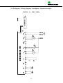
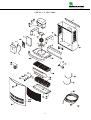
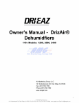
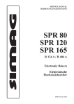
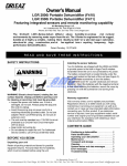
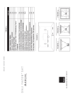
AFFUGTERE / DEHUMIDIFIERS /
ENTFEUCHTER / DESHUMIDIFICATEURS
CDF 10
No. 975677 - Version 1 - 14.03.02
DANSK
ENGLISH
DEUTSCH
FRANCAIS
SIDE
PAGES
SEITE
PAGES
1- 7
8 - 13
14 - 20
21 - 27
Der tages forbehold for trykfejl og ændringer.
Dantherm can accept no responsibility for possible errors and changes.
Irrtümer und Änderungen vorbehalten.
La responsabilité de Dantherm ne peut être engagée en cas d’erreurs et/ou
éventuelles modifications du présent document.
Contents
1. Description of function....................................................................................................................................9
1.1 Technical data........................................................................................................................................9
2. Installation of the unit....................................................................................................................................10
2.1 Suspension of the CDF 10 unit............................................................................................................10
2.2 Condensate outlet ................................................................................................................................10
2.3 Access to the control............................................................................................................................10
3. Connection of power supply..........................................................................................................................11
4. Operation .......................................................................................................................................................11
4.1 LED indication / Switch .......................................................................................................................11
4.2 Built-in hygrostat.................................................................................................................................11
4.3 Defrosting ............................................................................................................................................12
4.4 Safety circuit........................................................................................................................................12
4.5 Compressor control..............................................................................................................................12
5. Maintenance...................................................................................................................................................12
5.1 Cleaning of filter...................................................................................................................................12
5.2 Cleaning of the dehumidifier ...............................................................................................................13
6. Faults and how to remedy them.....................................................................................................................13
7. Cooling circuit................................................................................................................................................28
8. Wiring diagram ..............................................................................................................................................29
9. Spare parts and exploded views......................................................................................................................31
8
1. Description of function
CDF 10 is working in accordance with the condensation principle. The humid air is drawn into the unit by a fan.
When passing through the evaporator the air is cooled down to below dew point and water vapor is condensed into
water, which is drained away. The now dry air is then passed over the condenser coil where the air is heated. As a
result of the released evaporator heat and the working energy of the compressor being turned into heat energy,
more heat is returned to the air than was previously extracted. This extra heat corresponds to an approximate
increase in temperature of 5ºC. The repeated circulation of air through the unit reduces the relative humidity, giving
very rapid but gentle drying.
1.1 Technical data
Working area – humidity
Working area – temperature
Air volume at max. external
pressure
Power supply
Max. power consumption
Max. ampere consumption
Refrigerant
Quantity of refrigerant
Sound level (1 m away from unit)
Weight
Dimensions – H x L x W
%RH
ºC
CDF 10
40 – 100
3 - 32
m3/h
220
V/Hz
kW
A
1x230/50
0,39
2,1
R134a
0,190
46
27
600 x 535 x 240
Kg
dB(A)
Kg
mm
9
2. Installation of the unit
2.1 Suspension of the CDF 10 unit
The wall suspension bar supplied with the unit is fixed to the wall and the dehumidifier is hung up on it. It is
important to mount the unit in a horizontal position to secure correct outflow of the condensate water.
The dehumidifier must be placed in a way that allows unimpeded air intake through the front and outlet through the
grill on the sides. Be sure always to leave at least 100 mm free space around the unit for optimum operation.
NOTE! On the rear of the unit a cable binder protects the compressor
during transport. This cable binder must be removed before
suspension and power connection.
It is important that the dehumidifier is not installed near a source of heat as for example a radiator, and doors and
windows must be kept closed when the dehumidifier is in function.
2.2 Condensate outlet
The condensate outlet is located at the bottom of the dehumidifier. The unit has a drain spigot intended for
connection of a ½’’ flexible or fixed water connection. If water drain through the wall is chosen, a suitable hole is
made in the wall and the condensate hose is led out through this hole, before suspending the dehumidifier on the
wall suspension bar.
As an alternative a condensate pump can be fitted at the water outlet to pump the water to a drain.
The placing of the condensate outlet is shown on the drawing below.
10
2.3 Access to the control
Remove the front panel by unscrewing the two screws on the top of the dehumidifier. Lift the front panel vertically
upwards and then pull it horizontally away from the unit.
The control of the unit is located in a box behind the front panel. To get access to the control unscrew the 4 screws
on the sides.
3. Connection of power supply
The unit is delivered complete with cable and plug for connection to 230V / 50Hz.
Power is connected to the unit in accordance with the nameplate. Please refer to the wiring diagram on page 29.
NOTE! All electrical connections must be made in
accordance with local power supply
company regulations.
4. Operation
4.1 LED indication / Switch
The LED on the front of the unit is green when the compressor is operating, and the unit dehumidifies.
The dehumidifier is switched on and off by the switch on the side.
NOTE! Any stop of the unit - by failing power connection, by the switch or the
hygrostat - will make the electronic control put off re-start for 30 seconds in
order to protect the compressor from being switched on and off repeatedly.
4.2 Built-in hygrostat
The dehumidifier is controlled by a built-in hygrostat that is set to approx. 50% RH. When the hygrostat registers a
relative humidity of more than 50%RH, the compressor and the fan automatically switch on and the dehumidifier
starts to dehumidify. The hygrostat is located under the control box and is set on the hygrostat switch.
If you want to set the hygrostat at a lower relative humidity than 50% the set screw has to be turned clockwise.
11
NOTE! If the air humidity is below 50%RH, the unit will not
start when the power is connected.
4.3 Defrosting
If the temperature falls to below 20ºC the evaporator may start to ice up after a short time.
The defrosting function is activated when the evaporator sensor registers a temperature lower than 5ºC, after which
the control will let the unit operate in dehumidification mode for another 30 minutes. Then the compressor is
stopped and the unit switches over to active defrosting, which means that the cooling circuit turns and the hot
refrigerant runs through the evaporator coil and melts the ice. When the evaporator sensor registers that the
temperature is above 5ºC, the compressor starts again.
4.4 Safety circuit
If the temperature in the dehumidifier increases to a temperature of more than 55ºC (for example in case of fan
failure), the compressor stops automatically to avoid damaging it. After 45 minutes the compressor starts again
automatically.
By room temperatures outside the unit’s working range (3 - 32°C) it is automatically switched off to protect the
evaporator coil from icing up and the condenser coil from overheating. The unit will automatically start again when
the room temperature is within the working range.
4.5 Compressor control
The number of compressor starting is limited by a 6 minutes timer, which starts up when switching on the
compressor. The timer must have come to an end before the compressor can be switched on again.
Each time the unit has been switched off on the main switch, by the built-in hygrostat, or by an external hygrostat,
it will take 30 seconds before the unit can be switched on again. This is a safety function protecting the compressor
against overloading caused by too high pressure in the cooling circuit at start up.
5. Maintenance
The dehumidifier requires very little attention for trouble free running. All the necessary safety and control
functions have been built in. The fan motor and the compressor have permanent lubrication and require no
particular maintenance.
5.1 Cleaning of filter
Once a month the air inlet filter should be checked and cleaned if necessary. The front cover panel is removed and
the filter taken out. Clean the filter in tepid soapy water or if not badly soiled by vacuum cleaning.
12
5.2 Cleaning of the dehumidifier
Once a year the front cover panel should be removed in order to check the inside of the dehumidifier. If the
dehumidifier is dirty it should be cleaned by vacuum cleaning. The condenser in particular should be thoroughly
vacuumed. If the lamella evaporator is badly soiled, it may be washed in tepid soapy water.
6. Faults and how to remedy them
The dehumidifier does not start when power is connected
1. Check external fuses
2. Check that the power supply to the units is correct
3. Check that the switch on the side is ON
4. Check the built-in hygrostat by setting it on a lower relative humidity. This is done by turning the hygrostat
knob clockwise. If the unit does not start, check the built-in hygrostat for faults.
The unit was switched off automatically. If it starts after 45 minutes, but switches off again shortly
afterwards, check the following:
5. Check that the fan is running when the unit starts after 45 minutes
6. Check whether the condensor coil is dirty
7. Check whether the filter is dirty
8. Check whether the room temperature is above 32ºC. If so, and the unit has not automatically been switched
off, it should be switched off.
9. Check that the air inlet on the front and the air outlet through the grill on the sides are not blocked.
The evaporator coil has iced up and the unit does not separate water
10. Check whether the room temperature is below 3°C. If so, and the unit has not automatically been switched
off, it should be switched off.
If you cannot find the reason for the fault, switch off the unit immediately in order to prevent further damage.
Contact a service technician or a Dantherm representative.
NOTE! If the dehumidifier is not functioning
correctly, shut it down immediately.
Disposal
This unit contains refrigerant type R134a and compressor oil. When scrapping the unit, bring the compressor to a
place of discharge, which is approved by the authorities.
13
7. Kølekredsløb / Cooling Circuit / Kältekreislauf / Circuit de réfrigération
CDF 10
1.
2.
3.
4.
5.
6.
7.
Kompressor, compressor, Kompressor, compresseur
Fordamper, evaporator, Verdampfer, évaporateur
Luftkølet kondensator, air-cooled condensor, luftgekühlter Kondensator, condenseur à air
Kapillarrør, capillary tube, Kapillarrohr, tubes capillaires
Tørfilter, liquid line drier, Trockenfilter, filtre anti-humidité
Magnetventil, solenoid valve, Magnetventil, vanne magnétique
Ventilator, fan, Ventilator, ventilateur
28
8. El-diagram / Wiring diagram / Schaltplan / Schéma électrique
CDF 10 - 1 x 230V / 50Hz
29
Ordforklaring til el-diagram / Legend for wiring diagram /
Legende für Schaltplan / Légende du schéma électrique
CDF 10
Position
TS1
TS1
M2
Y1
M3
Beskrivelse
Kondensatorføler
Fordamperføler
Ventilator
Magnetventil
Kompressor
Designation
Condenser sensor
Evaporator sensor
Fan
Solenoid valve
Compressor
30
Beschreibung
Kondensatorfühler
Verdampferfühler
Ventilator
Magnetventil
Kompressor
Désignation
Sonde du condenseur
Sonde d’évaporateur
Ventilateur
Vanne solénoïde
Compresseur
CDF 10 - 1 x 230V / 50Hz
31
CDF 10 - 1 x 230V / 50Hz
Pos.
1
2
3
3a
3b
4
5
6
7
8
9
10
11
12
13
14
15
16
17
18
19
20
21
22
22a
23
24
25
26
27
28
29
30
31
31a
31b
31c
32
33
34
Dantherm. no.
084767
293647
601933
510051
510052
084766
084753
532480
532520
084764
084765
517581
517599
605440
605470
517802
517804
084750
515081
084751
600990
084752
516350
293646
921343
541774
607410
435620
198332
293645
544150
524890
540131
293644
528117
528627
084771
527500
526900
084772
Beskrivelse
Vægbeslag
Kabinet kpl.
Kompressor
Startrelæ
Beskyttelse for relæ
Designation
Wall suspension bar
Housing, cpl.
Compressor
Starting relay
Overload protector for relay
Beschreibung
Wandkonsole
Gehäuse, kpl.
Kompressor
Startrelais
Schutz für Relais
Description
Barre d’ancrage
Carrosserie cpl.
Compresseur
Relais de démarrage
Protection du relais
Ventilatormotor
Ventilatorvinge
Fan motor
Fan blade
Ventilatormotor
Ventilatorflügel
Moteur de ventilateur
Ailette du ventilateur
Printkort
Diodeprint
Spole for magnetventil
Magnetventil
Føler, metalnæse, 1150mm
Føler, 1250mm
Printed circuit board
Diode print
Coil for solenoid valve
Solenoid valve
Sensor, metal nose, 1150 mm
Sensor, 1250 mm
Printplatte
Diodenprint
Spule für Magnetventil
Magnetventil
Fühler, Metallnase, 1150 mm
Fühler, 1250 mm
Platine électronique
Platine de diode
Bobine de la vanne magnétique
Vanne magnétique
Sonde, nez métallique, 1150 mm
Sonde, 1250 mm
Vippeafbryder
Toggle switch
Kippschalter
Interrupteur basculant
Kondensatorflade
Condensor
Kondensator
Condenseur
Hygrostat
Holder for hygrostat
Skala for hygrostat
Drejeknap
Tørrefilter
Kapillarrør
Fordamper
Drypbakke, kpl.
Afløbsstuds
Tilslutningskabel
Afstandsstykke
Front, kpl.
Skilt – Dantherm logo
Skilt – CDF 10
Filter
Kontramøtrik
Kabelforskruning
Isolering
Hygrostat
Retainer for hygrostat
Scale for hygrostat
Adjusting knob
Liquid line drier
Capillary tube
Evaporator
Condensate tray, complete
Drain spigot
Connection cable
Spacing piece
Front panel, complete
Label – Dantherm logo
Label – CDF 10
Filter
Counter nut
Screwed cable entry
Insulation
Hygrostat
Halter für Hygrostat
Skala für Hygrostat
Drehknopf
Trockenfilter
Kapillarrohr
Verdampfer
Kondensatschale, kpl.
Ablaufstutzen
Anschlusskabel
Distanzrohr
Deckplatte vorne, kpl.
Aufkleber – Dantherm Logo
Aufkleber – CDF 10
Filter
Gegenmutter
Kabelverschraubung
Isolierung
Hygrostat
Support de l’hygrostat
Cadran de l’hygrostat
Bouton rotatif
Filtre anti-humidité
Tubes capillaires
Evaporateur
Bac à eau, cpl.
Orifice d’écoulement
Câble de raccordement
Pièce d’écartement
Tôle frontale, cpl.
Etiquette – Dantherm logo
Etiquette – CDF 10
Filtre
Contre-écrou
Raccord à vis pour le cable
Isolant
32
33
34
35
36