1
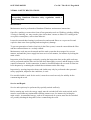
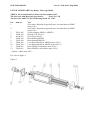
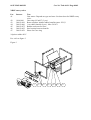
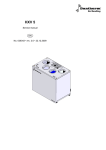
LANGUAGE :
ENGLISH GB
X
GERMAN D
FRENCH F
DANISH DK
SWEDISH S
FINNISH FIN
DUTCH NL
ITALIAN I
SPANISH E
RUSSIAN
MANUAL No. 08002.0621
Machine : Rotary valve, NRSZ4, -10, -20, -30 & NRSZ3
Art. no.: 74004.xxx, 74010.xxx, 74020.xxx, 74030.xxx & 399012.x95
Content
------Declaration
: 74004.xxx, 74010.xxx, 74020.xxx, 74030.xxx & 399012.x95
Safety Instruction:
Cat.20/Tab.05.51/06.01-06.02
Packing / Transportation Manual:
Cat.20/Tab.06.21/04.01
Installation Manual:
Cat.20/Tab.06.21/05.01-05.02
User Manual:
Cat.20/Tab.06.21/07.01-07.02
Maintenance Manual:
Cat.20/Tab.06.21/08.01-08.03
Spareparts List:
Cat.20/Tab.06.21/09.01-09.02
Demounting Manual:
See Maintenance Manual
Producer : Dantherm Filtration A/S , Assens, DK 9550 Mariager, Denmark.
01JULY05 1005GB
Cat. 20 / Tab. 05.01 / Page 06.01
NF2000 - SAFETY REGULATIONS
Disregarding Dantherm Filtration safety regulations entails a
heavy safety risk.
Maintenance.
Maintenance must be performed to Dantherm Filtration maintenance instructions.
Open fire, sparking or some other form of heat generation such as: Welding, grinding, drilling
/ boring or smoking, etc. may not take place closer than 3 metres to filters etc. working with
an explosive atmosphere, such as dust laden air.
It must be ensured that cleaning is performed on and around filters etc. to prevent fire and
explosive dust waste from igniting and causing heavy damage.
To prevent generation of static electricity in the filter system, it must be ensured that the filter
and the connected ducts etc. are duly earthed.
Maintenance work may not be started until the total system has been stopped in a correct
manner, and until the power supply has been cut in a safe manner, for instance by locking the
main switch.
Inspection of the filter hopper section by opening the inspection doors at the gable ends may
not be performed until the filter air flow has been thoroughly reversed, and the hopper section
emptied of material. In this connection, it must be checked whether the reversed air flow has
been adequate by examining the residual dust settlement on the filter bags.
Inspection by opening inspection doors and similar may only be performed when personal
safety equipment, adapted to the conditions, is used.
If a movable ladder is used for the work, it must be secured correctly for stability before
commencing the work.
Service and Repair.
Service and repair may be performed by specially trained staff only.
Before starting any work, the energy supply must be switched off at the main switch, and it
must be ensured that any unintended restarting cannot occur, for instance by locking the
main switch. Accumulated energy, such as in compressed air system, must also be switched
off, possibly discharged altogether, before commencing the work.
01JULY05 1005GB
Cat. 20 / Tab. 05.01 / Page 06.02
For service and repair work making it necessary to be in dust laden air, for instance in the
filter hopper section, the following safety equipment must be used:
1
Respiratory Protective Device, possibly with fresh air supply.
2
Goggles, possibly a screen mask in connection with fresh air supply.
3
Fire-Retardant Suit.
4
Fire-Retardant Working Gloves.
5
Safety Footwear.
6
Safety Helmet.
7
Non-Sparking Tools wherever possible.
Inspection of the filter bags when staying at the filter top after opening of the explosion relief
doors may be performed only when the filter system has stopped.
For this purpose, the personal safety equipment referred to above must also be used.
If the filter or similar is cleaned by a vacuum cleaner, protection must be established against
static electric charging in the suction arrangement.
Boring of holes in filter housing or adjoining pipe ducts may be made only when the system
has stopped and been cleaned, while taking great care and without heat generation.
If any fault(s) should occur in the electric system, stopping the system, and restart is
disconnected, the faulty component may not be removed to allow for further operation.
Proper troubleshooting and repair must be performed before restarting.
Disposal of replaced components, dust/waste from cleaning, as well as other waste, must be
performed to the guidelines for the particular materials. These guidelines have normally been
established by the local authorities. In case of doubt, the person responsible for company
safety must be consulted.
01JULY05 1002GB
Cat. 20 / Tab. 06.21 / Page 04.01
PACKING/SHIPPING/TRANSPORT INSTRUCTION
for Rotary Valve type NRSZ.
Rotary valve type NRSZ is packed on a wooden pallet.
Pallet 800 x 1200 is used for NRSZ 3, NRSZ 4 and NRSZ 10
Pallet 600 x 2000 is used for NRSZ 20 and NRSZ 30
Type
Weight / kg
Dimensions LxWxH
NRSZ 3
37
1200x 800x 600
NRSZ 4
90
1200x 800x 600
NRSZ 10
125
1620x 800x 600
NRSZ 20
200
2670x 600x 600
NRSZ 30
275
2670x 600x1000
The above weights are incl. packaging.
Transport can be carried out using normal pallet handling equipment. When using a crane
lift, the lifting strap must be fastened carefully at least two flange holes at each end.
Despatch may be effected by all means of transport normally used. For sea carriage,
supplementary protection should be considered.
01JULY05 1002GB
Cat. 20 / Tab. 06.21/ Page 05.01
MOUNTING INSTRUCTION for Rotary Valve type NRSZ
Before any kind of activity, the NF FILTER 2000 or NF 10 SAFETY REGULATIONS
must be read carefully, and the safety regulations must be strictly adhered to.
The rotary valve is certified for use as explosion pressure isolation. The actural dust and
pressure shall be inside the specifications for the rotary valve. For further info, see the data
sheet, the declaration and the ATEX guidelines.
The rotary valve is mounted by fastening to material inlet and material outlet to the square
flanges of the rotary valve. If inlet/outlet do not have sufficient stability for the normally
occurring loads from the rotary motion of the rotary valve, including start-up, additional
stiffening should be made. These stiffening must be fastened to the flanges.
When mounting inlet and outlet, avoid jutting edges, flats, and similar which may inhibit the
free material flow.
The placing of the rotary valve appears from a plant view plan, allowing for servicing to be
performed, including dismantling of motor and rotor, and allowing for power connection to be
made.
When placing in places at the risk of inadequate cooling of the electric motor, another placing
should be considered, external cooling established, or special thermal protection considered.
Connect the electric motor of the rotor valve according to the power current regulations in
force and make earthing.
As long as the rotary valve is not connected both at the material inlet side and at the
material outlet side, it must not be possible to set the rotary valve into operation.
During operation, it may be appropriate for the rotary valve to rotate in a fixed direction but
normally this is without any importance. The rotation direction used during test is preferred
subsequently. By reverse rotation direction the rubber lips may freeze the rotary valve.
When putting into operation, check ampere consumption.
After completing mounting, check that there is an electric connection between material inlet
and material outlet so that no static electricity can arise.
As the rotary valve contains mechanically movable parts, all components connected must
prevent personal contact with the rotary parts. As an example, the following must be met:
All joints up to 1 metre from the rotary valve may only be taken apart by tools (flange
connections meet this requirement).
Access doors may only be opened by tools.
The connected controller must ensure the stopping of the rotary valve type NRSZ if an
explosion occurs.
01JULY05 1002GB
Cat. 20 / Tab. 06.21 / Page 07.01
USER INSTRUCTION for Rotary Valve Type NRSZ
Before any kind of activity, the NF FILTER 2000 or NF 10 SAFETY REGULATIONS must
be read carefully, and the safety regulations must be strictly adhered to. If any deviations are
made from the safety regulations, this may cause serious personal injury. Before restarting,
guards, hatches/doors etc. must be closed/reestablished.
Your rotary valve is produced by:
Dantherm Filtration A/S
Assens
DK-9550 Mariager
Denmark
Phone +45 99 68 09 00
Rotary valve type NRSZ is designed to be incorporated as a part element of a complete
material transport system.
Operation, such as start/stop of the rotary valve, does not occur in normal working situations.
The rotary valve will normally be controlled by a central control system for the material
transport system of which the rotary valve forms part.
Troubleshooting Assistance:
All troubleshooting and fault remedying activities may by performed by skilled competent
staff only, with knowledge of the plant function and build-up.
Safety regulations NF FILTER 2000 or NF 10 should be read before commencing
activities, and be observed during performance.
Before restarting, all guards, doors/hatches, etc. must be reestablished.
The rotary valve must be examined carefully after an evt. explosion / fire. If the rotary valve
is not completely without damages and without visible changes, the rotary valve must be
changed in order to preserve the security level.
01JULY05 1002GB
Cat. 20 / Tab. 06.21 / Page 07.02
Fault
Possible Cause
Activity Proposal
Rotary valve disconnecting
thermally
∗ Jammed tramp material
∗ Remove tramp material
∗ Rotor frozen
∗ Thaw outside with hot
air/water
∗ Gear motor faulty
∗ Replace gear motor
∗ Rotor faulty
∗ Replace rotor
∗ Thermal protection preset
wrongly
∗ Adjust thermal protection
∗ Fuse faulty
∗ Replace fuse
∗ Large voltage drop in power
supply
∗ Replace cables to larger
square
∗ Operating switch off
∗ Stop system, switch not
running on operating switch
Rotary valve
∗ Thermal protection thermally
∗ See under fault:
Thermally disconnected
∗ Condition for operation not
met in control system
∗ Examine why condition not
met
∗ Fuses faulty
∗ Mount fuses
Rotary valve making
∗
∗ Remove tramp material
"screeching" sound
∗ Rotor/rotor housing faulty
∗ Replace faulty parts
Material cannot pass valve
∗ Material volume per time unit
larger than planned in periods
∗ Reduce material volume
supplied, e.g. at chain filters
without accumulation
Jammed tramp material
∗ more frequent regeneration
∗ briefer step interval on chain
conveyor
∗ Air flow opposite through
rotary valve easily obstructing material passage
∗ Material fall velocity less than
anticipated
∗ Material collecting in tufts,
lumps which cannot pass
∗ Material not being removed
quickly enough at rotary valve
outlet side
∗ Replace tightening lamellas
∗ Adjust production machine so
as to change material
∗ Adjust production machine so
as to change material
∗ Check emptying system
function
01JULY05 1002GB
Cat. 20 / Tab. 06.21/ Page 08.01
MAINTENANCE INSTRUCTION for Rotary Valve type NRSZ
Before any kind of activity, the NF FILTER 2000 or the NF FILTER 10 SAFETY
REGULATIONS must be read carefully, and the safety regulations must be strictly
adhered to.
If any deviations are made from the safety regulations, this may cause serious personal injury.
Before restarting, guards, hatches/doors etc. must be closed/reestablished.
The following elements are to be maintained regularly at the intervals stated. The briefest
interval shall apply. If any wear or similar is found, the faulty parts must be replaced.
Maintenance:
Monthly/Operating Hours Interval
Clean gear motor of any
dust encrustation and similar
1
500
Fill up the grease chamber *
2
500
Check rotor housing, shaft
seal, etc., outside and
motor bracket for wear, etc.
6
1,000
Check rotor housing inside for
wear, tramp material, and
similar
2
1,000
Check rotary valve (lamellas,
shaft, etc.) for wear and
similar
2
1,000
Check and grease rotary valve
bearings *
6
1,000
Check gear motor for oil waste
6
1,000
Check connected transport pipes
for wear and similar
6
1,000
* A more detailed maintenance instruction is found on the following pages.
01JULY05 1002GB
Cat. 20 / Tab. 06.21/ Page 08.02
Rotary valve type NRSZ 4, -10, -20 and -30
Filling up the grease chamber:
See figure 1, point 5.
Between the bearing and the end plate of the rotary valve there is a chamber which when
filled up with grease prevents dust from getting into the surroundings. The chamber is filled
via the lubricator nipple near the end plate of the rotary valve. Castrol LM Grease can be
used.
Greasing of Rotary Valve Bearings:
The bearings are supplied greased with CASTROL LM Grease.
Regrease with the same or a similar grease type.
Gear Motor:
The gear motor is lubricated for life and demand no further maintenance. In case of oil waste
the gear motor must be changed.
Figure 1.
5
4
6
3
2
1
01JULY05 1002GB
Cat. 20 / Tab. 06.21/ Page 08.03
Changing the rubber lamellas in the rotary valves type NRSZ
Pull out the rotor from the rotary valve when changing the rubber lamellas and the end sealing
plate. In connection with the mounting af the new rubber lamellas, all screws must be placed
in the holes, before fastening. Check that the lamellas are secured to the shaft.
Dismantling
Dismantling may be performed after an external lift (for instance a crane) has been
established, and the rotary valve has been cleaned inside of toxic, explosive or otherwise
dangerous material.
After cleaning, the rotor valve consists of steel, rubber, copper, lubricant, plastic, and paint.
01JULY05 1002GB
Cat. 20 / Tab. 06.21/ Page 09.01
LIST OF SPARE PARTS for Rotary Valve type NRSZ
NRSZ-4, 10, 20 and 30 delivered since the late summer 1997.
The first ones with Motovario gear motor:
Prod. No. 1710
The first ones with UCF 207 ø35 bearings Prod. No. 1790
Pos.
1
Item no.
2
3
5
6
7
8
9
10
11
12
70011.005
70000.190
18160.035
70004.100
70010.100
74004.700
74010.700
74004.016
74010.016
Text
Gear motor. Depends on type and zone. See data sheet for NRSZ
rotary valve.
Gear motor. Depends on type and zone. See data sheet for NRSZ
rotary valve.
Clutch complete NRSZ4 / NRSZ10
Bearing UCF 207 ø35
Gaco ring ø35x62x7
Rotor housing NRSZ4
Rotor housing NRSZ10
1 set rubber lamella for NRSZ4 (max. 50°C) *
1 set rubber lamella for NRSZ10 (max 50°C) *
Rotor NRSZ4, with rubber (max 50°C) *
Rotor NRSZ10, with rubber (max 50°C) *
* Option – rubber max. 80°C.
Pos. refer to figure 2.
Figure 2
01JULY05 1002GB
Cat. 20 / Tab. 06.21/ Page 09.02
NRSZ rotary valves
Pos.
41
Item no.
42
43
44
45
46
47
18160.001
399012.030
399012.090
399012.075
399012.055
399012.070
Text
Gear motor. Depends on type and zone. See data sheet for NRSZ rotary
valve.
Gaco ring ø25-ø42-7 (3 pcs.)
Rotor complete include rubber lamellas (max. 50°C)*
1 set rubber lamells (9.pcs.). Max. 50°8C *
Rubber enclosure for rotor
Steel section between lamella
House for Gaco ring
*Option: rubber 80°C
Pos. refer to figure 3.
Figure 3
41
47
42
45
44
43
46