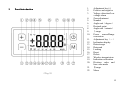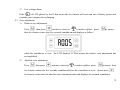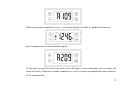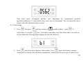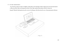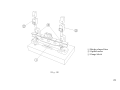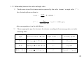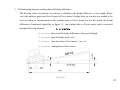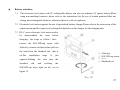
1
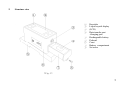
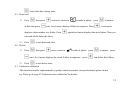
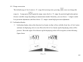
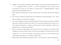
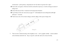
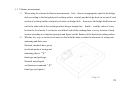
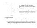
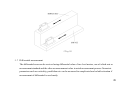
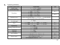
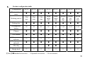
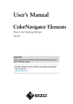
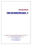
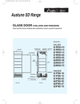
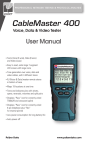
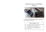
User Manual for Electronic Level Meter Qingdao Rulazix Electronics Corporation Contents 1. Preface ..............................................................................4 2. Structure view ........................................................................5 3. Panel introduction.....................................................................6 4. Functions description...................................................................7 4.1 Turn on/off........................................................................7 4.2 Voltage detection/Low voltage alarm....................................................7 4.3 Zero adjustment.....................................................................8 4.4 Data storage.......................................................................10 4.5 Data read .........................................................................11 4.6 Delete............................................................................11 4.7 Indication calibration ...............................................................11 4.8 Range conversion ..................................................................12 4.9 Inclination display. ................................................................12 5. Basic operations.......................................................................13 5.1 Attentions before use ...............................................................13 5.2 Working surface level adjustment......................................................15 5.3 Straightness measurement...... .....................................................16 2 5.4 Flatness measurement...............................................................18 5.5 Verticality measurement.............................................................19 5.6 Parallelism measurement............................................................19 5.7 Differential measurement ...........................................................20 5.8 Online measurement................................................................21 5.9 Indication error calibration...........................................................22 5.10 Relationship between line value and angle value .......................................24 5.11 Relationship between reading data and height difference .................................25 6. Maintenance for level meter.............................................................26 7. Battery attentions .....................................................................27 8. Technical specifications .................................................................29 9. Product configuration table..............................................................30 Warranty and Service card..............................................................31 Qualified Certification........................................... ......................33 Version:20100123 3 1. Preface Please read this manual carefully before using the product.All the contents of this manual use RL-AP5 type for example besides the contents of the attached figures.The functions and basic operations of other types please consult RL-AP5 type except certain type which has some special provisions.If you have any question please contact us.We will wholeheartedly serve you. RL series of electronic level meter is suitable to measure the tilt angle relative to horizontal plane as well as to measure straightness, flatness ,verticality, parallelism, levelness and other geometrical parameters.It is widely used for the installation and adjustment of exact plat ,exact machine tool ,CNC machine center and other apparatuses.The measured data can be transmitted to a computer which can compute the data with software RL-LM and print the inspection report. This manual implementes national metrological verification of The People's Republic of China JJG103-2005.If you want to know its specific prescriptions ,please read the national metrological verification. Qingdao Rulazix corporation is continuously dedicated to develop the function and performance of this product ,so we reserve the right to improve the functions of any product described in this manual without prior notice. 4 2. Structure view ① ② ③ ④ ⑤ ⑥ ⑦ ⑧ ⑨ Keystoke Liquid crystal display (LCD) Data transfer port /charging port Rechargeable battery Pedestal Crust Battery compartment Set screw (Fig.1) 5 3. 1. 2. 3. Panel introduction 4. 5. 6. 7. 8. 9. 10. 11. 12. 13. 14. 15. 16. 17. 18. 19. 20. 21. 22. Adjustment key(+) Positive and negative Voltage detection/Low voltage alarm Zero adjustment Number Angle unit(degree) Decimal point Angle unit(minute) Ⅰrange Power source/Range conversion Adjustment key(-) Inclination display Data storage Data read Locking Reset Delete Wireless transmission Indication calibration Division value and line value mode Ⅱrange Menu (Fig.2) 6 4. Functions description 4.1 Turn on/off 1) Turn on Press last for more than two seconds to turn on the level meter 2)Turn off Press last for more than three seconds to turn off the level meter from boot-strap state 4.2 Voltage detection/Low voltage alarm 1) Voltage detection Press ,the on LCD will glitter,then press again,the level meter displays the current voltage of battery.When the voltage drops below 6V, you should prepare to charge the battery .The voltage of battery displayed in the following figure is 8.6V.Press to exit voltage detection. 7 2) Low voltage alarm If the on LCD glitters by itself ,that means the level meter will soon run out of battery power and reminds you to prepare for recharging. 4.3 Zero adjustment 1) Relative zero adjustment Press ,then press and move cursor to to make it glitter,press to ensure, then level meter comes into five seconds countdown and displays as follow: when the countdown is over,the LCD displays“0”.That means the relative zero adjustment has accomplished. 2) Absolute zero adjustment Press then press and move cursor to to make it glitter,press to ensure,then level meter comes into five seconds countdown,before the countdown is over,please press , level meter comes into the absolute zero adjustment state and displays ten seconds countdown. 8 When ten seconds countdown is over,level meter displays the data A1 gathered at that time. next it displays ten seconds countdown again. At this time you need to treat level meter with 180 degree in-situ rotation(try best to ensure the return of in-situ). When ten seconds countdown is over,level meter accomplish the data collection of A2 automatically. 9 Next level meter accomplish absolute zero adjustment by computing.In practical application,influences of some factors may cause error in adjustment. You can repeat the above steps to make the adjustment more accurate. 4.4 Data storage 1) Press then press ensure.Here, if you press and move cursor to to make it glitter,press to once , level meter establishes a new data folder and it can create up to four folders,the following figure displays the first data folder b1. 2) Press once,level meter displays a data number. Press again ,after about 5 seconds countdown,level meter stores the datas automatically. A data folder can save up to 25 datas. Press 10 to exit the data storage state. 4.5 Data read 1) Press then press at this time press and move cursor to to make it glitter,press once ,level meter displays folders in sequence. Press displays a data number in a folder. Press to ensure, ,level meter again,level meter displays the saved datas. Then you can read all the datas like these. 2) Press 4.6 Delete 1) Press to exit data read state. then press move cursor to to make it glitter,press once ,level meter displays the saved folders in sequence,press 2) Press to ensure,press can delete this folders. to exit delete state. 4.7 Indication calibration This function must be implemented by quality control personnel, non-professionals please do not try.Please go to page 22“Indication error calibration”for details. 11 4.8 Range conversion The default range of level meter is Ⅱ range.In boot-strap state ,pressing range to Ⅰrange,press once can chenge the again,the range comes back to Ⅱ range. In practical application,please choose a suitable range depending on measurement needs.Generally, you can choose Ⅰrange to make low-precision adjustment ,and then choose Ⅱ range to make high-precision adjustment. 4.9 Inclination display 1) Inclination display shows the direction level meter incline to.Face with the front face of level meter and tune its displaying value to zero.Drive the left of level meter up,the displaying value will be positive. Drive the right of level meter up,the displaying value will be negative,as the following figure shows (Fig.3) 12 2) When the declining angle of level meter beyonds its normal display range,it displays as follow 5. Basic operations 5.1 Attentions before using level meter 1) Installing battery and charging Please do in sequence as Fig.1 shows,remove the set screw,dump the battery compartment, (notice: please do not over-pull the wires),buckle the polar plate according to battery polarity,put the battery into the battery compartment,push the battery compartment into the casket lightly and tighten the set screw ,then accomplish the installation of battery. When you use level meter for the first time,please charge the battery at first.When you install the battery of RL-C series level meter , please see page 27“attention for battery”for details.But when you do with RL-F series level meter,you should remove battery cover at first,then you can put battery into the battery compartment and tighten the battery cover. 13 2) Maintain a clean working environment without vibration, keep the environment temperature is 20 ℃ ± 2 ℃,temperature drift is less than 1 ℃ per hour and humidity is not more than 75%.If necessary,please process the environment in advance,such as suspension,dustproof, constant temperature,constant humidity and so on. 3) Please eradicate antirusting grease on the working surface of level meter and clean the measured plane. 4) If level meter is needed to be placed in the work environment for more than an hour(off),please turn it on and keep it is in power for 30 minutes. 5) If you need to change environment during the operation of level meter,please must reserve sufficient time and you had better put the device which is to be measured touching with level meter into a room where the temperature is constant to make them have the same temperature. Otherwise the instrument may be in unusual circumstances! 6) When you operate level meter,please wear yarn gloves.If you do so,neither can avoid human body touching the level meter directly which can lead to partial temperature fluctuation because of heat conduction so as to affect the reliability of measurement results,nor can avoid human sweat contacting the mental parts so as to erode the working surface. 7) When you have done all the above preparatory works,you can use the level meter to do detection. 14 5.2 Working surface level adjustment First ,you should adjust the working surface to a horizontal position roughly,then put the level meter on the working face which will be measured, and record the displaying value a of this place(A), then treat level meter with 180 degree in-situ rotation, and record the displaying value b of this place(B), so the declining angle α of the working surface relative to horizontal is:: The zero point error δ of level meter is: a +b δ = 2 α = a −b 2 Adjust the working surface according to the calculated results, and make the level meter at A, B and in the X axis and Y axis direction are equal in displaying value respectively, then the measured working surface is adjusted horizontally.Show in Figure 4 (Fig.4) 15 【e.g.】The value of level meter at A is a=80, treat level meter with 180 degree in-situ rotation,the value at B is = -20,so the zero point error δ is: δ = a+b = 30 2 Adjust the working surface at A,B and in theX and Y direction repeatedly until all the values of level meter are 30,then the working surface is adjusted to horizontal position. 5.3 Straightness measurement 1) Level meter is used to use “Pitch method”to Pitch method:Divide the measured implement straightness measurement,see figure section into several segments using the 5.There will be error in measuring straightness,so bridge deck,then level meter read the please pay attention to the following notices: tilt angle or height difference which is Please adjust the measured working surface to horizontal position roughly before measuring. Fix the level meter on the bridge deck and avoid a value of the two measurement lines relative to measurement baseline in each segment and figure out the its movement relative to bridge deck during straightness error by dealing with the measurement. datas. Choose appropriate span l for bridge deck according to measurement accuracy and length L and ensure L/l is an integer. The direction of level meter should be consistent with the direction of movement during 16 measurement(placing battery compartment to the left and moving from left to right). Ensure the convergence of the head with the end and the trajectory is a beeline during movement of bridge deck. Ensure the measured line is consistent with measurement baseline. Pay attention to the unit conversion,see page 25“relationship between reading data and height difference”for detail. The division value of level meter changes with the change of the span of bridge deck. (Fig.5) 2) There are three methods dealing with straightness error,such as graphic method、rotation method and calculation method.In fact,they are equal to each other and can be chosen flexibly. 17 5.4 Flatness measurement 1) When using level meter do flatness measurement,first,choose an appropriate span for the bridge deck according to the being detected working surface;second,put the bridge deck on an end of each section of working surface and put level meter on bridge deck;then move the bridge deck from one end to the other side of the working surface along a straight line;finally,read the value of every location by level meter. Level meter would deal with all the reading datas at every location of each section according to evaluation principle and figure out the flatness of the detected working surface. 2) Whether it is easy or not for level meter to deal with the datas is related to the mode of wiring and stationing and their error. National standards have given two kinds mode of wiring and stationing, that is“米” front-type and grid-type. National metrological verification recommend“米” front-type,see figure 6. (Fig.6) 18 5.5 Verticality measurement 1) Refer to amount of change of the measured actual element to the ideal element which squares to the standard.It is evaluated according to the method of directional minimum area. 2) Handheld RL-AC1 type electronical level meter touches the measured surface with its right-angle working surface and the verticality error to the standard surface can be received after data process as shown in figure7.The correlative rules can be used smartly in actral measurement。 (Fig.7) 5.6 Parallelism measurement 1) Level meter measures parallelism error usually using directional minimum area contains the measured actual element parallels to the standard element according to the minimum condition. 2) For example, the parallelism error between the long-narrow and stagewise surfaces can be received using level meter measures continuously the actral standard surface and the measured actral surface respectively as shown in figure8. 19 (Fig.8) 5.7 Differential measurement The differential error can be received using differential value of two level meters, one of which acts as measurement standard and the other as measurement value in actral measurement process.Geometric parameters such as verticality, parallelism etc can be measured in complicated and volatile situation if measurement of differential is used neatly. 20 5.8 On-line measurement Level meter connects with a computer using data wire through its data output port to run measurement software,collect data on-line,process data in real time and get detection results as shown in figure9.Detailed information can be received refering to the direction for use of measurement software. (Fig.9) 21 5.9 Indication error calibration Indication error calibration of electronic level meter should be carried out on small-angle tester.See in figure 10,the steps as follow: 1) First, the bridge-shaped face of small-angle tester should be adjusted to horizontal position. 2) Level meter will be placed on the flat working surface of small-angle tester, and be consistent with it in vertical direction. 3) Put two 1mm gauge blocks under the optical meters of the small-angle tester and adjust the value of optical meter to zero. 4) Adjust the indication value of level meter to zero,then replace the 1mm gauge block with a 1.25mm one under the right optical meter,adjust the small-angle tester to make the indication value of level meter to be zero,at that time the displaying value of level meter should be 500.If the displaying value is not 500,please record the actual value,and press to make it glitter,press then press move cursor to to ensure,level meter gets into the indication value calibration state ,input the changed data for the actual displaying data, adjust the current gain of level meter, you can achieve the calibration for the indication error. 5) Repeat the above steps until the displaying value of level meter is right. 22 ① Bridge-shaped face ② Optical meter ③ Gauge block (Fig.10) 23 5.10 Relationship between line value and angle value 1) The division value of level meter can be expressed by line value(mm/m)or angle value(") , the relationship between them is: 1 rad = 1 ″ = 360° 2π ≈ 206265 ″ 2π (rad)= 0.005 mm/m 360 × 60 × 60 their correspondence is in the table below: 2) Choose appropriate type for electronic level meter according to the accuracy grades, see in the following table: Type Division value(mm/m) Angle value(″) Accuracy grade RL-A Ⅱrange = 0.001 mm/m 0.2″ 00 grade RL-B Ⅱrange = 0.005 mm/m 1″ 0 grade Ⅰrange = 0.01 mm/m 2″ 1 grade 、2 grade RL-A / RL-B 24 5.11 Relationship between reading data and height difference The division value of electronic level meter is defined as the height difference of 1m length ,Where 1m is the uniform provision.Not all spans of level meter’s bridge deck are 1m,they are needed to be sure according to measurement,so the reading datas of level meter are not the actual tilt height difference of measured length.See in figure 11,the reading data a of level meter can be converted through following formula: h = L×C×a h ──── the actual tilt height difference of measured length L ──── span of bridge deck(mm) C ──── division value of level meter(mm/m) a ──── reading data of level meter (Fig.11) 25 6. Maintenance for level meter 6.1 Please use level meter depending on the methods provided in this manual.Non-professional please do not disassemble this instrument. 6.2 Electronic level meter is an so precision instrument that it is needed to be taken and set lightly.Please pay attention to protect the working surface from getting rusty and bump, so as not to affect the measurement accuracy.After using level meter,please lay anti-rust grease on the working surface. 6.3 Please do not use and store this instrument in high humidity,high temperature,low temperature, magnetic, dust, vibration, corrosion, electrostatic and other harsh environments. 6.4 The working surface with V-shaped groove of level meter is not used as a measuring surface. 6.5 Level meter should be sealed in a dry bag into the box for a long-term storage and keep the box vertically to prohibit stand on side face and tilt. 6.6 The following cases, please referred to the professionals to deal with: 1) Level meter subjects to rain ,water or other liquid. 2) There are peculiar smell,smoke or high temperature within level meter. 3) Level meter is bumped so severely that leads damage to LCD as well as to the crust. 4) The working surface of level meter is seriously rusted or bumped. 5) You have operated the level meter according to the manual, but it still can not work normally. 6.7 In order to ensure the accuracy of measurement, electronic level meter should be tested regularly by professional departments, its test cycle generally do not exceed one year. 26 7. Battery attentions 7.1 The electronic level meter with 9V rechargeable battery can also use ordinary 9V square battery.When using non-matching batteries, please refer to the instructions for the use of related products.Must not charge non-rechargeable batteries, otherwise there is a risk of explosion. 7.2 Electronic level meter supports the use of specialized battery charger.Please refer to the conversion of the output current and the capacity of rechargeable batteries on the charger for the charging time. 7.3 RL-C series electronic level meter need to be disassembled the strut before charging,the steps as follow:first, remove the SOC.HD.cap screw with Allen key counter-clockwise,then pull out the strut form the sheathed rod,that is ok.The installation opposite.Pushing the sheathed and rod steps is just strut into the twisting ① ② ③ ④ Allen key SOC.HD.cap screw Strut Sheathed rod the SOC.HD.cap screw tight are ok,see in figure 12. (Fig.12) 27 7.4 Do not disassemble the battery, short circuit, or throw it into the fire, otherwise the battery may cause an explosion. 7.5 Do not use the charger at high temperature, high humidity environment. 7.6 Please use genuine battery and auxiliary battery charger. 7.7 If level meter is not used for a long-term, please make sure the battery is fully charged ,removed , stored in a cool dry place and recharged every three months.The battery must not be placed in the level meter for a long-term, because if doing like that,there may be damage to the level meter and battery. 7.8 After the battery end its life, please put it to the designated outlets. Qingdao Rulazix electronics corporation Tel. 0532-84760717 Fax : 0532-84891335 Contact: Liu Weiliang Mobile Tel. 13864228317 E-mail: [email protected] Address: No.8,Xingtai Road,Licang District,Qingdao 28 8、 Technical specifications Technical specifications Display range Measurement range Resolution Indication error Consistency of zero point for each range Drift Repeatability Reading stabilization time Zero error Verticality Test condition Power source Requirements 0 ~ ±5000(number) ≤ ±500(number) Ⅰ range = 0.01 mm/m Ⅱ range = 0.001 mm/m Ⅰ range = 0.01 mm/m Ⅱ range = 0.005 mm/m Within Measurement range:±(1+A×2%) (A is the absolute value of normal value at test location) Type RL-A RL-B ≤ 1digit ≤ 6 digits / 4h,≤ 3 digits / h(Ⅱrange) ≤ 4 digits / 4h,≤ 1 digits / h(Ⅱrange) ≤ 1 digit ≤ 10 seconds ≤ 5 seconds ≤ 1 digit ≤ 0.008mm ( 20 ± 2 )℃ 0.5 ℃ / h ( 20 ± 5 )℃ 1.0 ℃ / h One rechargeable battery(9 V) One rechargeable batteries(3.6V) RL-A RL-B RL-A RL-B RL-C、RL-F RL-A RL-B RL-P、RL-C RL-F 29 9、 Product configuration table Configuration RL-P1 RL-P2 RL-P5 RL-C1 RL-C2 RL-FT RL-FL RL-FS Electronic level meter ● ● ● ● ● ● ● ● Working surface Flat type Flat type Flat type Right angle type Right angle type Rectan gle type Rectan gle type Rectan gle type Packing box ● ● ● ● ● ● ● ● Rechargeable battery 9V 9V 9V 9V 9V 3.6V 3.6V 3.6V Charger ● ● ● ● ● ● ● ● User manual ● ● ● ● ● ● ● ● Measurement software Dual-purpose end-mill ○ ○ ○ ○ ○ ○ ○ ○ ● ● ● ● ● ● ● ● Allen key ― ― ― ● ● ― ― ― Bridge deck ○ ○ ○ ○ ○ ○ ○ ○ 【Note】●Standard accessories ,○Optional accessories,―No accessories 30 Warranty and Service card Thanks for your trust and support to electronic products of Rulazix. We will be happy to provide you with satisfactory service. To protect your legal rights and interests,we make the following pledge to you. 1、 Wherever the sale of the company's products, customers with purchase invoices and vouchers to benefit warranty from the effective date of purchase within one year. Electronic level meter enjoys a warranty for one year, annex enjoys (rechargeable batteries, charger) warranty for six months and measurement software enjoy life free service. 2、 Electronic Level meter can enjoy three-month replacement.We will solve the product which is needed to be repaired within seven days,if there are special circumstances,we will consult with you. 3、 Anyone of the following conditions is outside the scope of the warranty. For non-warranty products the company will provide maintenance service for fee. The products beyond the warranty period. Products subject to inundating, falling, knocking, dump, high temperature, magnetic, corrosion and other causes of damage. Damage cased by illegal dismantling and repaired by non-designated agency personnel. Damage cased by accident or other force majeure. Other damage cased by failure to follow the manual about useness and maintenance. 4、 The warranty and service card is a warranty certificate for electronic products of Rulazix, other procedures which are not listed performe in accordance with the relevant provisions of consumer protection law.Rulazix has the right to interprete,change and revise the regulations. In conformity with the relevant laws and regulations Rulazix reserves final interpretation of this ordinance. 31 Dear customer, the following information is provided by dealers who are responsible for completing and sealed, which will serve as your warranty certificate, in order to protect your rights, please cooperate with us,thank you! Name Custom er Address and postcode Telephone E-mail Name Invoice number Type Product number Product Name Dealer Address and postcode Telephone Sale date Note: Do not arbitrarily alter and safekeep the warranty card. For service or have any questions, please consult a local dealer or us. 32 Qualified Certificatiion Type: Number: Inspector: Date: 33