1
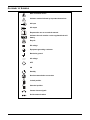
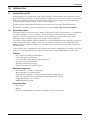
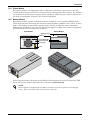
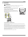
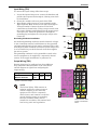
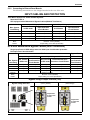
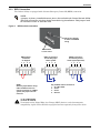
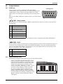
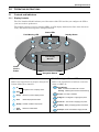
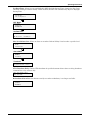
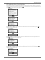
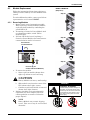
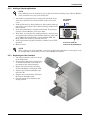
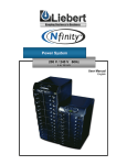
AC Power
For Business-Critical Continuity™
Liebert® Nfinity™ Power System
User Manual – 208/240 V, 60 Hz, 4 to 16 kVA
TABLE OF CONTENTS
IMPORTANT SAFETY INSTRUCTIONS . . . . . . . . . . . . . . . . . . . . . . . . . . . . . . . . . . . . . . . . . . . . . . . .1
GLOSSARY OF SYMBOLS . . . . . . . . . . . . . . . . . . . . . . . . . . . . . . . . . . . . . . . . . . . . . . . . . . . . . . . .2
1.0
INTRODUCTION . . . . . . . . . . . . . . . . . . . . . . . . . . . . . . . . . . . . . . . . . . . . . . . . . . . . . . . . . .3
1.1
General Description . . . . . . . . . . . . . . . . . . . . . . . . . . . . . . . . . . . . . . . . . . . . . . . . . . . . . . . . . . 3
1.1.1
System Description. . . . . . . . . . . . . . . . . . . . . . . . . . . . . . . . . . . . . . . . . . . . . . . . . . . . . . . . . . . . 3
1.2
Modes of Operation. . . . . . . . . . . . . . . . . . . . . . . . . . . . . . . . . . . . . . . . . . . . . . . . . . . . . . . . . . . 5
1.3
Major Components . . . . . . . . . . . . . . . . . . . . . . . . . . . . . . . . . . . . . . . . . . . . . . . . . . . . . . . . . . . 6
1.3.1
1.3.2
1.3.3
1.3.4
1.3.5
Unit Frame . . . . . . . . . . . . . . . . . . . . . . . . . . . . . . . . . . . . . . . . . . . . . . . . . . . . . . . . . . . . . . . . . .
User Interface Module . . . . . . . . . . . . . . . . . . . . . . . . . . . . . . . . . . . . . . . . . . . . . . . . . . . . . . . . .
System Control Module . . . . . . . . . . . . . . . . . . . . . . . . . . . . . . . . . . . . . . . . . . . . . . . . . . . . . . . .
Power Module . . . . . . . . . . . . . . . . . . . . . . . . . . . . . . . . . . . . . . . . . . . . . . . . . . . . . . . . . . . . . . . .
Battery Module . . . . . . . . . . . . . . . . . . . . . . . . . . . . . . . . . . . . . . . . . . . . . . . . . . . . . . . . . . . . . . .
6
6
6
7
7
2.0
INSTALLATION . . . . . . . . . . . . . . . . . . . . . . . . . . . . . . . . . . . . . . . . . . . . . . . . . . . . . . . . . .8
2.1
Inspection . . . . . . . . . . . . . . . . . . . . . . . . . . . . . . . . . . . . . . . . . . . . . . . . . . . . . . . . . . . . . . . . . . 8
2.1.1
2.1.2
2.1.3
2.2
Unloading . . . . . . . . . . . . . . . . . . . . . . . . . . . . . . . . . . . . . . . . . . . . . . . . . . . . . . . . . . . . . . . . . . 9
2.2.1
2.2.2
2.3
Unloading the UPS. . . . . . . . . . . . . . . . . . . . . . . . . . . . . . . . . . . . . . . . . . . . . . . . . . . . . . . . . . . . 9
Stationary Mounting . . . . . . . . . . . . . . . . . . . . . . . . . . . . . . . . . . . . . . . . . . . . . . . . . . . . . . . . . 10
Cable Installation . . . . . . . . . . . . . . . . . . . . . . . . . . . . . . . . . . . . . . . . . . . . . . . . . . . . . . . . . . . 11
2.3.1
2.3.2
2.3.3
2.4
Environment . . . . . . . . . . . . . . . . . . . . . . . . . . . . . . . . . . . . . . . . . . . . . . . . . . . . . . . . . . . . . . . . . 8
Required Setup Equipment . . . . . . . . . . . . . . . . . . . . . . . . . . . . . . . . . . . . . . . . . . . . . . . . . . . . . 8
Site Preparation . . . . . . . . . . . . . . . . . . . . . . . . . . . . . . . . . . . . . . . . . . . . . . . . . . . . . . . . . . . . . . 8
Wiring Preparation. . . . . . . . . . . . . . . . . . . . . . . . . . . . . . . . . . . . . . . . . . . . . . . . . . . . . . . . . . . 11
Connecting to External Panel Boards . . . . . . . . . . . . . . . . . . . . . . . . . . . . . . . . . . . . . . . . . . . . 13
REPO Connection . . . . . . . . . . . . . . . . . . . . . . . . . . . . . . . . . . . . . . . . . . . . . . . . . . . . . . . . . . . . 15
Communications . . . . . . . . . . . . . . . . . . . . . . . . . . . . . . . . . . . . . . . . . . . . . . . . . . . . . . . . . . . . 16
2.4.1
2.4.2
COM Ports. . . . . . . . . . . . . . . . . . . . . . . . . . . . . . . . . . . . . . . . . . . . . . . . . . . . . . . . . . . . . . . . . . 16
Liebert IntelliSlot Ports . . . . . . . . . . . . . . . . . . . . . . . . . . . . . . . . . . . . . . . . . . . . . . . . . . . . . . . 16
3.0
OPERATING INSTRUCTIONS . . . . . . . . . . . . . . . . . . . . . . . . . . . . . . . . . . . . . . . . . . . . . . . . 17
3.1
Controls and Indicators . . . . . . . . . . . . . . . . . . . . . . . . . . . . . . . . . . . . . . . . . . . . . . . . . . . . . . 17
3.1.1
Display Controls . . . . . . . . . . . . . . . . . . . . . . . . . . . . . . . . . . . . . . . . . . . . . . . . . . . . . . . . . . . . . 17
3.2
Status LED Modes . . . . . . . . . . . . . . . . . . . . . . . . . . . . . . . . . . . . . . . . . . . . . . . . . . . . . . . . . . 18
3.3
Navigating the Menu . . . . . . . . . . . . . . . . . . . . . . . . . . . . . . . . . . . . . . . . . . . . . . . . . . . . . . . . 19
3.4
Operating Procedures. . . . . . . . . . . . . . . . . . . . . . . . . . . . . . . . . . . . . . . . . . . . . . . . . . . . . . . . 19
3.4.1
3.4.2
3.4.3
Start-Up and Initialization . . . . . . . . . . . . . . . . . . . . . . . . . . . . . . . . . . . . . . . . . . . . . . . . . . . . 19
Shutting Down the UPS. . . . . . . . . . . . . . . . . . . . . . . . . . . . . . . . . . . . . . . . . . . . . . . . . . . . . . . 19
Manual Transfer to Bypass . . . . . . . . . . . . . . . . . . . . . . . . . . . . . . . . . . . . . . . . . . . . . . . . . . . . 20
i
3.5
Main Menu . . . . . . . . . . . . . . . . . . . . . . . . . . . . . . . . . . . . . . . . . . . . . . . . . . . . . . . . . . . . . . . . 21
3.5.1
3.5.2
3.5.3
3.5.4
3.5.5
3.5.6
3.5.7
3.5.8
UPS Status Screen . . . . . . . . . . . . . . . . . . . . . . . . . . . . . . . . . . . . . . . . . . . . . . . . . . . . . . . . . . .
UPS Configuration Screen . . . . . . . . . . . . . . . . . . . . . . . . . . . . . . . . . . . . . . . . . . . . . . . . . . . . .
Display Date/Time . . . . . . . . . . . . . . . . . . . . . . . . . . . . . . . . . . . . . . . . . . . . . . . . . . . . . . . . . . .
Event Log . . . . . . . . . . . . . . . . . . . . . . . . . . . . . . . . . . . . . . . . . . . . . . . . . . . . . . . . . . . . . . . . . .
Active Alarms . . . . . . . . . . . . . . . . . . . . . . . . . . . . . . . . . . . . . . . . . . . . . . . . . . . . . . . . . . . . . . .
Transfer to Bypass . . . . . . . . . . . . . . . . . . . . . . . . . . . . . . . . . . . . . . . . . . . . . . . . . . . . . . . . . . .
Module Replacement . . . . . . . . . . . . . . . . . . . . . . . . . . . . . . . . . . . . . . . . . . . . . . . . . . . . . . . . .
Service Tools for Liebert Global Services Engineers . . . . . . . . . . . . . . . . . . . . . . . . . . . . . . . .
22
23
31
31
32
32
33
34
4.0
TROUBLESHOOTING . . . . . . . . . . . . . . . . . . . . . . . . . . . . . . . . . . . . . . . . . . . . . . . . . . . . . 36
4.1
Active Alarms . . . . . . . . . . . . . . . . . . . . . . . . . . . . . . . . . . . . . . . . . . . . . . . . . . . . . . . . . . . . . . 36
4.2
Module LED Indication . . . . . . . . . . . . . . . . . . . . . . . . . . . . . . . . . . . . . . . . . . . . . . . . . . . . . . 38
4.3
Module Replacement . . . . . . . . . . . . . . . . . . . . . . . . . . . . . . . . . . . . . . . . . . . . . . . . . . . . . . . . 39
4.3.1
4.3.2
4.3.3
Removing Modules . . . . . . . . . . . . . . . . . . . . . . . . . . . . . . . . . . . . . . . . . . . . . . . . . . . . . . . . . . . 39
Adding or Replacing Modules . . . . . . . . . . . . . . . . . . . . . . . . . . . . . . . . . . . . . . . . . . . . . . . . . . 40
Replacing the User Interface . . . . . . . . . . . . . . . . . . . . . . . . . . . . . . . . . . . . . . . . . . . . . . . . . . . 40
5.0
MAINTENANCE . . . . . . . . . . . . . . . . . . . . . . . . . . . . . . . . . . . . . . . . . . . . . . . . . . . . . . . . . 41
5.1
Maintenance . . . . . . . . . . . . . . . . . . . . . . . . . . . . . . . . . . . . . . . . . . . . . . . . . . . . . . . . . . . . . . . 41
5.1.1
5.1.2
5.1.3
Proper Care . . . . . . . . . . . . . . . . . . . . . . . . . . . . . . . . . . . . . . . . . . . . . . . . . . . . . . . . . . . . . . . . . 41
Scheduled Maintenance . . . . . . . . . . . . . . . . . . . . . . . . . . . . . . . . . . . . . . . . . . . . . . . . . . . . . . . 41
Replacing Fan Filters . . . . . . . . . . . . . . . . . . . . . . . . . . . . . . . . . . . . . . . . . . . . . . . . . . . . . . . . . 41
6.0
SPECIFICATIONS . . . . . . . . . . . . . . . . . . . . . . . . . . . . . . . . . . . . . . . . . . . . . . . . . . . . . . . .42
6.1
Product Warranty Registration . . . . . . . . . . . . . . . . . . . . . . . . . . . . . . . . . . . . . . . . . . . . . . . . 42
FIGURES
Figure 1
Figure 2
Front and back views (12 bay model shown) . . . . . . . . . . . . . . . . . . . . . . . . . . . . . . . . . . . . . . . . . . . 4
REPO switch connections . . . . . . . . . . . . . . . . . . . . . . . . . . . . . . . . . . . . . . . . . . . . . . . . . . . . . . . . . 15
TABLES
Table 1
Table 2
Liebert Nfinity weight and dimensions . . . . . . . . . . . . . . . . . . . . . . . . . . . . . . . . . . . . . . . . . . . . . . . 4
Guide to LEDs . . . . . . . . . . . . . . . . . . . . . . . . . . . . . . . . . . . . . . . . . . . . . . . . . . . . . . . . . . . . . . . . . . 38
ii
IMPORTANT SAFETY INSTRUCTIONS
SAVE THESE INSTRUCTIONS
This manual contains important instructions that should be closely followed during installation and
maintenance of this UPS unit and during the installation and replacement of Power and Battery
Modules.
This product is designed for Commercial/Industrial use only. This product is not intended for use
with life support and other U.S. FDA-designated “critical” devices. Maximum load must not exceed
that shown on the UPS rating label.
! WARNING
Lethal voltages may be present within this unit even when it is apparently not operating.
Observe all cautions and warnings in this manual. Failure to do so MAY result in serious
injury or death. Never work alone.
Observe the following precautions when working with batteries:
! CAUTION
DO NOT dispose of Battery Modules in a fire because the modules may explode.
DO NOT open or mutilate batteries; released electrolyte is harmful to skin and eyes and may
be toxic.
A battery can present a risk of electrical shock and high short-circuit current. The following
precautions should be observed when working on batteries:
• Remove watches, rings and other metal objects.
• Use tools with insulated handles.
Lead-acid batteries contain hazardous toxic materials. Handle, transport and recycle in
accordance with local regulations.
This UPS is designed for use on a properly grounded (earthed), 208/240 VAC, 60 Hz supply and is to
be installed by qualified personnel.
Electromagnetic Compatibility—The Liebert Nfinity UPS complies with the limits for a Class A
digital device, pursuant to Part 15 of FCC rules. These limits provide reasonable protection against
harmful interference in a commercial environment. This device generates, uses and radiates radio
frequency energy and, if not installed and used in accordance with the instruction manual, may cause
harmful interference to radio communications. Operating this device in a residential area is likely to
cause harmful interference which users must correct at their own expense.
Operate the UPS in an indoor environment only in an ambient temperature range of 32°F to +104°F
(0°C to +40°C). Install it in a clean environment, free from conductive contaminates, moisture,
flammable liquids, gases and corrosive substances.
Turn the UPS off and isolate the UPS before cleaning. Use only a soft cloth, never liquid or aerosol
cleaners. Keep the front and rear vents free of dust accumulation that could restrict airflow.
Never block or insert any object into the ventilation holes or other openings.
This UPS contains user replaceable modules. No attempts should be made to access the interior of
any module. See 4.3 - Module Replacement.
1
GLOSSARY OF SYMBOLS
Risk of electrical shock
Indicates caution followed by important instructions
AC input
AC output
i
Requests the user to consult the manual
Indicates the unit contains a valve-regulated lead acid
battery
Recycle
DC voltage
Equipment grounding conductor
Bonded to ground
AC voltage
OFF
ON
Standby
No telecommunication connection
Locked position
Unlocked position
Contact closure signals
Serial communications
2
Introduction
1.0
INTRODUCTION
1.1
General Description
Congratulations on your purchase of the Liebert Nfinity™ Uninterruptible Power System. As with
every other Emerson product, we stand behind our quality. If you have any questions concerning this
UPS, please feel free to contact your local dealer or Liebert representative or call the appropriate
Technical Support number listed on the back of this manual.
To ensure proper installation and operation of this unit, please read this manual thoroughly.
For details on product warranty and registration, see 6.1 - Product Warranty Registration.
1.1.1
System Description
The Liebert Nfinity Power System is a modular UPS available in 8 & 12 bay frames. It is intended for
use with workstations, servers, network, telecom and other sensitive electronic equipment. It
provides continuous, high-quality AC power to your equipment, protecting it from any power
disturbance due to blackouts, brownouts, surges or noise interference.
The Liebert Nfinity modular UPS was designed to provide maximum system availability to businesscritical equipment. Liebert Nfinity is also an easily adaptable UPS system. By simply installing
additional Power or Battery Modules, you can expand your current system capacity or extend your
backup runtime.
Liebert Nfinity has a comprehensive user interface that enables configuration according to the user’s
preference. It also informs the user of details on the status of the UPS and keeps a log of events.
Features
•
•
•
•
•
•
Up to 16kVA of modular backup power
Continuous power conditioning
A user-friendly interface for custom configuration
Continuous system monitoring
Warning alarms and event logs
Internal automatic and manual bypass
Standard Components
•
•
•
•
•
•
Power Modules - for power conditioning
Battery Modules - for backup power
System Control Modules - for system monitoring and communications
LCD - for comprehensive user indications and programmable controls
Output Transformer - for isolation
REPO Switch Connection
Communications
• Dry contacts
• RS-232
• Optional communications via Liebert IntelliSlot™ communication ports
3
Introduction
Figure 1
Front and back views (12 bay model shown)
User Interface
Control
Switch (SW2)
REPO
Connection
Liebert IntelliSlot
Communications Ports
!
ESC
DB-9
Communication
Ports
Power
Module
Bays
Battery
Module
Bays
Output Power
Terminal
208/240 Jumper
Input Power
Terminal
Input Earth
Terminal
Manual
Bypass
Switch
(SW1)
Input Circuit
Breaker (CB1)
External Battery
Connection
Intake
Cooling Fans
FRONT VIEW
with bezels
removed
BACK VIEW
with access
plates removed
Refer to the table below for size and fully populated weight considerations.
Table 1
Liebert Nfinity weight and dimensions
Model
Max Weight - lb (kg)
W x D x H - in. (mm)
8 bay
855 (388)
20 x 28 x 40 (508 x 711 x 1016)
12 bay
1176 (534)
20 x 28 x 53 (508 x 711 x 1346)
4
Introduction
1.2
Modes of Operation
INPUT
MANUAL
BYPASS
EMI
FILTER
OUTPUT &
BYPASS
CONTACTOR
POWER
MODULE(S)
OUTPUT
OUTPUT
TRANSFORMER
BATTERY
MODULE(S)
USER
INTERFACE
CONTROL
INTERFACE
COMMUNICATIONS
SYSTEM
CONTROL
MODULE(S)
POWER
CONTROL
Normal Mode
The Power Module rectifiers derive power from a utility AC source and supply regulated DC power to
the inverter. The module’s inverter regenerates precise AC power to supply the connected equipment.
The battery charger is in the Power Module and maintains a float-charge on the batteries.
Backup Mode
When AC utility fails, the connected equipment is supplied power by the inverter, which obtains
energy from the Battery Modules. The output power equipment will not be interrupted during the
failure or restoration of the AC utility source.
Auto Restart Mode
After a power outage and complete battery discharge, and once AC utility is restored, the UPS will
automatically restart and resume supplying power to connected equipment. This feature is enabled at
the factory, but can be disabled by the user. The user can also program two auto restart delay settings:
1. Battery capacity level (%)
2. Countdown timer
Bypass Mode
The bypass provides an alternate path for power to the connected equipment and operates in the
following manner:
• Automatic
In the event of an internal fault or should the inverter overload capacity be exceeded, the UPS
performs an automatic transfer of the connected equipment from the inverter to the bypass
source.
• Manual
Should the UPS need to be taken out of service for limited maintenance or repair, manual activation of the bypass will cause an immediate transfer of the equipment from the inverter to the
bypass source.
5
Introduction
1.3
Major Components
Liebert Nfinity’s frame
with bezels removed
The following is a general description of each
component and its functions. Please review this
section carefully, as it will give you a better
understanding as to how the Liebert Nfinity operates.
1.3.1
Unit Frame
The front of the Liebert Nfinity consists of a series of
plastic bezels. By grasping these bezels from the left
and right sides and pulling straight out, you can
remove the bezel to reveal the Battery / Power
Module bays. The bottom bezel covers the internal
cooling fans and the manual bypass switch.
The User Interface Module is located above the
Power / Battery Module bays for easy access. By
moving the User Interface and setting it on top of the
frame, you will see the system control module bays.
NOTE
In the figure at right, the Power Module and
Battery Module are extended for illustration
purposes only. Extending more than one
module at a time could cause the unit to be
top-heavy and/or tip.
1.3.2
User Interface Module
User Interface Module
The User Interface Module is the primary source of
communication between the UPS and the user. From
the interface, the user can:
• View the status of the UPS
• Custom configure the system
• Review the event log to assist with
troubleshooting
• Enable/disable the output power
• Silence the audible alarm
• Manually transfer the unit to bypass
For a more detailed explanation on how to operate the
User Interface Module, see 3.1 - Controls and
Indicators.
1.3.3
System Control Module
System Control Module
The System Control Module is the communications
backbone of the UPS. It gathers input from all
modules and processes the data to control the
operation of the system — including monitoring the
condition of each module. An optional redundant
System Control Module can be installed to provide
full system functionality (operation and
communication).
Under normal operation, the Status LED (green) will
blink and the Fault LED (yellow) will be off. For any
condition other than this, check 4.0 Troubleshooting.
6
Fasteners
Fault LED
Status LED
Lever
Introduction
1.3.4
Power Module
Each power module is an independent 4 kVA, 2.8kW unit, consisting of a power factor corrected
rectifier, battery charger and inverter, with associated monitoring and control circuitry. The modules
are paralleled to provide greater capacity and/or redundancy. Modules may be added or replaced online with no interruption or danger to the connected equipment.
1.3.5
Battery Module
Each battery module contains 10 individual 12-volt, 9 amp hour, valve-regulated (VRLA) battery
blocks with associated monitoring and controls to isolate the Battery Module in the event of a battery
failure. The modules are paralleled to provide greater capacity, backup time and/or redundancy.
Modules may be added or replaced on-line with no interruption or danger to the connected equipment,
provided that the UPS is not operating on battery.
Power Module
Battery Module
Shipping screws
Fastener
Green Status LED
Yellow Fault LED
Cooling Fan
Lever
FRONT
FRONT
Under normal operation, the Green Status LED will blink continuously and the Yellow Fault LED
will be off. For any condition other than this, check 4.0 - Troubleshooting.
NOTE
Liebert Nfinity is shipped with each battery module secured to the frame by two shipping
screws. These screws should be removed prior to start-up.
7
Installation
2.0
INSTALLATION
2.1
Inspection
Upon receiving the UPS, examine the packaging for any signs of mishandling or damage. If any
damage is noted, call your local dealer or Liebert representative and/or notify your carrier.
2.1.1
Environment
NOTE
Operating in temperatures above 77°F (25°C) will reduce battery life. The UPS environment
must be free of conductive contaminants and excessive moisture (water and condensation),
flammable vapors, chemical fumes, corrosive gases and liquids.
2.1.2
Required Setup Equipment
The tools below are required to properly set up your UPS:
•
•
•
•
•
2.1.3
Pallet jack
1/2" (13mm) ratchet or wrench
Torque wrench (in-lb)
Flathead screwdriver
#2 Phillips screwdriver
Site Preparation
When deciding where to locate your UPS,
consider the weight and size of the unit. Make
sure that the structural integrity of the floor
can withstand the weight of a fully loaded unit.
Check to make sure that your UPS will be
located in a well-ventilated area with at least
12 inches (305mm) behind it. The UPS is
air-cooled utilizing internal fans. Air is drawn
into the front of the UPS and is exhausted
through ventilation grilles in the back. It should
also have at least 36 inches (915mm) in front in
order to change modules when necessary.
12"
(305mm)
36"
(915 mm)
The unit frame is bolted to the shipping pallet to ensure safety. It is recommended that a pallet jack
be used to transport the unit to its operating location (prior to unbolting the unit).
8
Installation
2.2
Unloading
2.2.1
Unloading the UPS
! CAUTION
This UPS is very heavy (see weight in
2. Remove the metal ramp from the bottom of
the UPS.
Table 1). At least two people should
assist in unloading it from the pallet.
Pull ramp out from
under front of unit,
then turn ramp over
3. Fit the ramp flange in the slot in the rear
of the pallet (back of unit) as shown below.
1. Use a ratchet or wrench, 1/2" (13mm), to
remove the four mounting bolts from the
front and rear pallet brackets. Remove the
mounting brackets from the pallet and
UPS. Keep the brackets for future
transportation of the UPS or for additional
stability of the UPS once in place.
9
Fit ramp in
rear of pallet
4. Using two people, slowly move the UPS
down the ramp until the UPS is on a level
surface.
Installation
5. Once the UPS is in the desired location, adjust the leveling feet to secure its position.
1/2" (13mm)
Stationary Mounting
Additional stability can be added by bolting the mounting brackets (used in shipping) to the floor, as
shown below left.
Optional Stationary
Mounting Dimensions
Shipping Brackets Used
for Stationary Mounting
4.75"
(120mm)
28"
(711mm)
4.75"
(120mm)
Center Line
2.2.2
5/16" (7.94mm)
diameter - in six
places
For greater stability, use a higher-grade bolt. Refer to the dimensions above right when drilling holes
for stationary mounting.
10
Installation
2.3
Cable Installation
2.3.1
Wiring Preparation
! WARNING
Please read this section thoroughly before attempting to install wiring to this unit.
This UPS should be installed by a qualified / certified electrician.
Removing the Cover Plates
On the back of the UPS, cover plates are over the input and output
terminals, as shown at right. Keep screws and plates to one side.
Remove Cover Plates
Configuring the Bypass Voltage (TB2)
The UPS voltage is factory-set to 208 V. Should the user have a
utility supply of 240 V, the bypass voltage jumper will have to be
changed to ensure correct output voltage. After selection, retorque
jumper screws to 28 in-lb.
Bypass Voltage Jumper
OR
208 V
(default)
240 V
Customer-Provided Overcurrent Protection
A branch rated overcurrent protection device (circuit breaker or fused disconnect switch) must be
installed for the AC input.
If the start-up is on bypass, the UPS has a six-cycle inrush current that is up to 20 times the rated
output current. This must be taken into account when selecting the overload protection device at the
AC input supply distribution point. To avoid random tripping on start-up, it is recommended that the
AC input supply be protected with a circuit breaker capable of withstanding this initial inrush.
This UPS is fitted with EMI suppression filters. Earth leakage current is less than 40mA. Transient
and steady state earth leakage currents may occur when starting the equipment. This should be
taken into account when selecting ground current detection devices, as the earth leakage currents of
both the UPS and load will be carried.
Input and output cables must be run in separate conduits.
11
Installation
Input Wiring (TB1)
To connect the input wiring, follow these steps:
1. Locate the input wiring access, remove the knockout and
pull the three input wires through it, allowing some slack
for installation.
2. Secure the conduit to the rear panel of the UPS.
3. Input Power cables connect to screw terminals on the
Input Terminal Block located to the right of the Bypass
Voltage Terminal. Connect the wires to the block
connections as shown below. Using a torque wrench, turn
the screws clockwise until tightened to the proper torque
value (28 in-lb). Insert the ground wire through the
grounding lug and tighten it to the proper torque value
(120 in-lb).
TB1
Grounding Conductor Installation
An insulated grounding conductor must be identical or larger
in size, insulation material, and thickness as the grounded
and ungrounded branch circuit supply conductors. This cable
must be green with or without one or more yellow stripes and
is to be installed as part of the branch circuit that supplies
the unit or system.
L1
L2
1
2
The grounding conductor is to be grounded to earth at the
service equipment or, if supplied by a separately derived
system, at the supply transformer or generator set.
Output Wiring (TB3)
Output wiring may be configured one of two different
ways (240/120 or 208/120). Refer to the chart below
and the diagram at right when configuring the
output wiring.
Voltage
Between terminals
120
208
240
1&4
3&4
2&3
1&3
Use only the connections listed above. Other connections will
produce nonstandard voltages.
NOTE
The Liebert Nfinity UPS contains an
isolation transformer that generates a
neutral conductor for the connected
equipment. The UPS is a separately
derived source and contains a neutral to
ground bonding jumper. A grounding
electrode conductor (GEC) must be
installed in accordance with national and
local wiring codes and regulations.
12
Note the Neutral / Earth
jumper on the terminal
above
Installation
2.3.2
Connecting to External Panel Boards
The following instructions are also shipped attached to the rear of the unit.
INPUT CABLING AND PROTECTION
Table Below Applies to 4-16kVA Scalable Systems:
Stand-alone UPS or
UPS equipped with a Maintenance Bypass Cabinet (Without Transformer)
Max. System
Load Rating
Input Voltage – 208VAC
Recommended
Max. Current
Input Protection
in UPS mode
Circuit Breaker
4kVA
8kVA
12kVA
16kVA
Input Voltage – 240VAC
Recommended
Max. Current
Input Protection
in UPS mode
Circuit Breaker
18 amps
36 amps
50 amps
50 amps
15 amps
31 amps
50 amps
50 amps
53 amps
70 amps
75 amps
100 amps
46 amps
62 amps
75 amps
100 amps
Maximum: 35mm2 (2AWG)
Minimum: 16mm2 (6AWG)
Torque Rating: 2.5-3.0Nm (22-26in/lbs)
Terminal
Block
Details
UPS With Maintenance Bypass Cabinet (With Transformer)
Single Input Feed: All UPS ratings must use 100A input circuit breaker protection.
Dual Input Feed: See table below.
UPS Feed
Input Voltage – 208VAC
Bypass Feed
Input Voltage – 240VAC
208V or 240V
Recommended
Recommended
Max. Current
Max. Current
Recommended Input
Input Protection
Input Protection
Max. System
in UPS mode
in UPS mode Protection Circuit Breaker
Circuit Breaker
Circuit Breaker
Load Rating
4kVA
8kVA
12kVA
16kVA
18 amps
36 amps
50 amps
50 amps
15 amps
31 amps
50 amps
50 amps
100 amps
100 amps
53 amps
70 amps
75 amps
100 amps
46 amps
62 amps
75 amps
100 amps
100 amps
100 amps
Maximum: 35mm2 (2AWG)
Minimum: 16mm2 (6AWG)
Torque Rating: 2.5-3.0Nm (22-26in/lbs)
Terminal
Block
Details
Bypass Voltage Jumper Position (TB2)
Bypass Voltage Selection
208 VAC
240 VAC
(Factory Default)
(Field Change)
Jumper/link
on upper two
screws
Jumper/link
on lower two
screws
13
Installation
OUTPUT CABLING
UPS Output Terminal Block (TB3)
Connection to External Panel Boards
208 VAC
If connected equipment operates at 208VAC only, use a single-phase panel board connected to the UPS as follows.
Setup 1 - 208 VAC
Panel Board Input
Max output current = 77A
UPS Output TB3
1
1
208
L
2
L
3
208
L
2
L
3
4
4
Grounding Electrode Conductor
(Field connection must be made)
GEC
5
Grounding Electrode Conductor
(Field connection must be made)
GEC
5
G
Connected Equipment
Ground
208 VAC and 120 VAC
If connected equipment is a combination of 208 VAC and 120 VAC, use a three-phase panel board connected to
the UPS as follows.
Panel Board Input
Setup 2 - 120 VAC
Max output current = 67A
each 120 VAC circuit
L
1
120
2
120
120
L
3
N
GEC
4
208
120
Note: L2 to N
is 88 VAC
Grounding Electrode Conductor
(Field connection must be made)
208 VAC also
5
available
Grounding Electrode Conductor
as shown
(Field connection must be made)
connected
in Setup 1
UPS Output TB3
L3
1
L2
2
L1
3
N
GEC
4
5
G
CAUTION: It is important for the installing
electrician to clearly identify the connections for
future reference. Refer to NEC 215-8 and 210-4(d).
Connected Equipment
Ground
240VAC and/or 120VAC
If connected equipment operates at 240VAC only or 120VAC only or is a combination of both, use a single-phase
panel board connected to the UPS as follows.
Setup 3 - 240 VAC
Max output current = 67A
Panel Board Input
L
240
L
1
2
L
120 VAC also
available as shown
connected in Setup 2
3
120
GEC
5
Grounding Electrode Conductor
(Field connection must be made)
G
Connected Equipment
Ground
14
1
2
240
120
4
Grounding Electrode Conductor
(Field connection must be made)
UPS Output TB3
L
3
N
GEC
4
5
Installation
2.3.3
REPO Connection
The Liebert Nfinity is equipped with a Remote Emergency Power Off (REPO) connection.
NOTE
A jumper is factory installed between pins 1 & 2 to disable the Control Switch (SW2).
This will prevent the unit from being started during installation. This jumper must
be removed in order to start the unit.
Figure 2
REPO switch connections
Hanger for cable-tie
to strain relief REPO
wiring
REPO switch
on rear of unit
REPO jumper
connected
as shipped
1
2
3
4
REPO connections
for normally open
switch system
1
2
NOTE
Remove jumper before wiring.
If the installation does not
require connection to a REPO
system, the jumper must be
removed.
3
4
REPO connections
for normally closed
switch system (fail-safe)
1
2
3
4
Key to REPO switch connections
1. 24 V DC, 50mA
2. Sense
3. Sense
4. Ground
! CAUTION
To maintain safety, Signal Edge Low Voltage (SELV) barriers, and electromagnetic
compatibility, signal cables should be segregated and run separately from power cables.
15
Installation
2.4
Communications
2.4.1
COM Ports
Pin Assignment
Liebert Nfinity is able to communicate through multiple
communication ports simultaneously. Use only Liebert-provided
communication cards. Connect only Signal Edge Low Voltage
(SELV)/Class 2 circuits when connecting to any communication
port.
5
4
9
There are two DB-9 COM ports available on the rear of the Liebert
Nfinity.
3
8
2
7
1
6
COM1 - Relay Contacts
Relay contacts are available through a DB-9F communications connector. Contact closure provides
the following:
Pin
Assignment
1
Low Battery (normally open)
4
UPS shutdown in battery mode
(5-12 V DC for 1.5 sec)
5
Common
7
Low Battery (common)
8
On Battery (common)
9
On Battery (normally open)
These contacts are rated 48 VDC, 1 amp maximum and are compatible with Liebert MultiLink™
software.
COM2 - Serial
Liebert Nfinity is able to communicate via Liebert proprietary protocol. This communication port can
be used for serial communication with Liebert MultiLink software. For more detailed information,
please see the MultiLink software documentation on the CD shipped with the Liebert Nfinity. The
pin-out configuration of the DB-9 connector is:
Pin
2.4.2
Assignment
2
Transmit Data
3
Receive Data
5
Common
Liebert IntelliSlot Ports
The following communication cards may be used with Liebert Nfinity:
• Liebert IntelliSlot OpenComms Web Card—
allows the Liebert Nfinity to communicate intelligently with your Ethernet network. The OpenComms Web Card must be installed in port 1.
• Liebert IntelliSlot MultiPort4 cards—allows
up to four client computer systems to monitor
the status of Liebert Nfinity simultaneously.
• Liebert IntelliSlot Relay Contacts cards—
provides contact closures for remote monitoring
of alarm conditions; On Battery, On Bypass, Low
Battery, Summary Alarm, UPS Fault and On
UPS signals.
16
Port 1
COM 1
Port 2
Port 3
COM 2
Port 4
Operating Instructions
3.0
OPERATING INSTRUCTIONS
3.1
Controls and Indicators
3.1.1
Display Controls
The User Interface Module informs you of the status of the UPS and lets you configure the UPS to
your own needs or preferences.
The module consists of a series of Status LEDs, an LCD display window (four lines of 20 characters
each), and buttons for navigation, as displayed below.
Status LEDs
Fault/Warning LED
Standby Button
ESC
LCD Display
Window
Alarm
Silence
Button
Navigation Buttons
Buttons
Fault/Warning and Status LEDs
Refer to the legend below to properly navigate the
Liebert Nfinity User Interface.
Refer to the legend below to indicate occurrence
when an LED is lit.
Fault/Warning
Up
Solid - A UPS fault condition has occurred.
Flashing - A Warning has occurred. Consult event log.
- Navigates cursor on display menus
Down
AC Input - AC utility is available.
ESC
Escape - Returns to previous display screen
On Bypass - The Bypass is supplying the power.
Enter
- Selects displayed information
Inverter On - The inverter is supplying the power.
Standby - Enables / disables output power
On Battery - Battery is supplying power to the inverter.
Alarm
Silence - Mutes the audible alarm
AC Output - Power is available to supply the load.
17
Operating Instructions
3.2
Status LED Modes
LED Off
UPS is Off or Initializing
LED On
LED Flashing
UPS is On, Utility is Good
and Output is Off
UPS is On, Utility is Good
and Output is On
(Normal Operation)
UPS is On, Utility is Bad
and Output is On
(On Battery Operation)
UPS is On, Utility is Bad
and Output is Off
UPS is in Bypass Operation
(Manual or Automatic)
UPS is in Manual Bypass
Operation with Utility Out of
Bypass Operation Range
Shutdown Due to
End of Discharge
18
Operating Instructions
3.3
Navigating the Menu
To review or change any settings on the UPS, use the buttons on the User Interface shown at left.
Because some menus contain more than four rows of information, you may see an arrow on the
display pointing up or down (as shown below)—indicating to scroll using the
or
buttons.
If you are scrolling through any of the Main Menus, items will scroll one line at a time with the menu
heading on the top line:
UPS Status
Present Load
Redundant Status
Battery Status
Pressing
reveals:
UPS Status
Redundant Status
Battery Status
Volts/Amps/kVA
Note the arrows on the screen indicate that the user can scroll up or down to reveal more information.
3.4
Operating Procedures
3.4.1
Start-Up and Initialization
Follow these steps to start up the UPS.
1. Ensure the manual bypass switch is in UPS position. Close Input Circuit Breaker (CB1) and close
the Control Enable Switch (SW2). You should see the following on the LCD display window:
UPS Initializing
Please wait...
*Press
to Enable
UPS Output.
2. Press
or ESC button.
On Mains/Utility
Output % = xx
Battery Minutes yyy
Press
for menu
3. Press
3.4.2
to access the Main Menu.
Shutting Down the UPS
Use the following procedure to power down the UPS.
1. Press
to disable power from the connected equipment.
2. Verify request to disable the output by pressing
.
3. Turn off the Enable Switch (SW2). Open the Input Circuit Breaker (CB1).
19
Operating Instructions
3.4.3
Manual Transfer to Bypass
To manually transfer the UPS to bypass, move the manual bypass switch to the bypass position. The
manual bypass switch is behind the front bottom bezel. To transfer the UPS from bypass to normal
mode, follow the on-screen instructions.
Main Menu
> Transfer to Bypass
Transfer to Bypass
Press
for bypass
Press ESC to cancel
Assert manual bypass
Once
is pressed, the bypass alarm will annunciate and cannot be canceled until the manual bypass
switch is operated.
On Bypass
Manual
Bypass
Switch
On UPS
UPS on manual bypass
NOTE
The load is not protected from utility interruptions when the UPS is in bypass mode.
To transfer the UPS from bypass to normal mode, simply operate the manual bypass switch back to
the UPS position.
On return from bypass, the following screen will be displayed.
No active alarms
See Event Log
20
Operating Instructions
3.5
Main Menu
After initialization, the
button will take you to the Main Menu. From here you may check on the
status of the UPS, review the event log and active alarms, configure your UPS and even receive
instructions on replacing modules. The Main Menu is divided into eight sub-menus as shown below:
Main Menu
> UPS Status
UPS Configuration
Display Date/Time
Event Log
Active Alarms
Transfer to Bypass
Module Replacement
Service Tools
UPS Status
Event Log
Module Replacement
UPS Status
Present Load
Redundant Status
Battery Status
Volts/Amps/kVA
UPS Frequency
Bypass Information
UPS Information
Module Information
Event: xxx/xxx
xx
event message
event message
DD/MMM/YYYY HH:MM:SS
Module Replacement
Ctrl w/ Redundant
Ctrl w/o Redundant
Pwr w/ Redundant
Pwr w/o Redundant
Battery Module
UPS Configuration
Active Alarms
Service Tools
UPS Configuration
Review Settings
Change Settings
Service Mode
Active Alarms Message
Service Tools
UPS Test
Clear Failures
BM Cell Replacement
Reset Battery Stats
Reset Bypass Stats
Display Date/Time
Transfer to Bypass
Date/Time
xx/xx/xxxx
mm/dd/yyyy
Press
for bypass
Press ESC to cancel
Use the
and
submenu.
xx:xx:xx
hh:mm:ss
buttons to select the desired menu item and press
21
to access the appropriate
Operating Instructions
3.5.1
UPS Status Screen
From the Main Menu the user may select UPS Status and press
. Once at the UPS Status Screen,
the user may access any information on the present condition of the UPS. Note the chart below when
reviewing the UPS.
Main Menu
> UPS Status
UPS Configuration
Display Date/Time
Event Log
Active Alarms
Transfer to Bypass
Module Replacement
Service Tools
UPS Status
UPS Status
Present Load
Redundant Status
Battery Status
Volts/Amps/kVA
UPS Frequency
Bypass Information
UPS Information
Module Information
UPS Status menu options
Present Load
Volts/Amps/kVA
Module Information
On Mains/Utility
Output: kVA xx.x
Output: kW xx.x
Output: pf xx.x
Input
xxx VAC
xxx A
xx.x kVA
Main Control
S/N: xxxxxxxxxxxxxxx
FW ver: xxxx
Redundant Status
UPS Frequency
Redundant Status
PMs Installed xx
PM:N+1 redundant/non-redundant
SC:Redundant/(non-redundant)
UPS Frequency
Input Hz:
xx.x
Output Hz: xx.x
Battery Status
Battery Status
Voltage (VDC) xxx
Capacity % xxx
Status: charging
BMs Installed xx
Ext batt present: No
Discharge count: xxxx
Batt Usage Hr: xxxx.x
Output
xxx VAC
xxx A
xx.x kVA
Bypass Information
Redundant Control
S/N: xxxxxxxxxxxxxxx
FW ver: xxxx
User Interface
S/N: xxxxxxxxxxxxxxx
FW ver: xxxx
Bypass Reasons
Manual-User x
Overload
x
Other
x
Power Module
S/N: xxxxxxxxxxxxxxx
FW ver: xxxx
UPS Information
Battery Module
S/N: xxxxxxxxxxxxxxx
FW ver: xxxx
UPS Information
UPS ID: xxxxxxxxxxxx
xxxxxxxxxxxxxxxxxxx
22
Bays=x,XFMR=x
Defaults = xxxV/xxHz
Limit/Cnfg=xxxkVA/1x1
Model ID=x
Operating Instructions
3.5.2
UPS Configuration Screen
Review Settings
Follow this procedure to review your UPS configuration settings. Follow the menus below by pressing
and
to review the settings.
Main Menu
UPS Status
> UPS Configuration
Display Date/Time
Event Log
Active Alarms
Transfer to Bypass
Module Replacement
Service Tools
UPS Configuration
UPS Configuration
> Review Settings
Change Settings
Service Mode
Review Settings
Voltage
Frequency
Battery
Alarm
Service Contact
Auto Restart
UPS Shutdown Delay
Remote Shutdown
External Battery
Bypass Alarm Mode
Intelli-Battery Ca.
Air Filter Reminder
Guarantee Shutdown
Review Settings menu options
Voltage
Service Contact
External Battery
Voltage Settings
Input 208/120
Output 208
Service Contact
Liebert Corp.
External batt config
Amp.Hr
0000
Charge (A) 00.0
www.liebert.com
Frequency
Frequency Settings
Frequency Hz: 60
Sync Range Hz: +/- 5.0
Slew Range Hz/S: 3.0
Battery
Battery Settings
Test intrvl weeks: 2
on Wed 06:00
Low Batt Warn:2 min
Alarm
Alarm Settings
Redundant Alarm:
Enabled/Disabled
Max Load: Enabled/Disabled
Auto Restart
Auto Restart
Mode:
Disable
Batt %
0%
Delay
10
UPS Shutdown Delay
UPS Shutdown Delay
120 seconds
Remote Shutdown
Remote comm shutdown
Mode: Enable
23
Bypass Alarm Mode
Bypass Alarm Mode
Mode:
Enable
Intelli-Battery Ca.
Intelli-Batteries
0
Air Filter Reminder
Air Filter Reminder
Mode:
26 weeks
Guarantee Shutdown
Guarantee Shutdown
Mode: Enable/Disable
Operating Instructions
Change Configuration Settings - Change Settings Menu
Starting from the Main Menu, locate and press UPS Configuration. From the UPS Configuration
screen, select the Change Settings option. You may configure Liebert Nfinity from a large variety of
selections. Items indicated by an asterisk (*) are the selected settings.
Main Menu
UPS Status
> UPS Configuration
Display Date/Time
Event Log
Active Alarms
Transfer to Bypass
Module Replacement
Service Tools
UPS Configuration
UPS Configuration
Review Settings
> Change Settings
Service Mode
Change Settings
Input Voltage
Display Voltage
Frequency Sync Range
Frequency Slew Rate
Set Password
Auto Battery Test
Low Battery Warning
Auto Restart
User Settings
Set Date/Time
Max Load Alarm Set
UPS Shutdown Delay
Redund Alarm Set
Service Contact
Remote Shutdown
External Battery
Bypass Alarm Mode
Intelli-Batt Ca.
Air Filter Reminder
Guarantee Shutdown
Line Compensation
Factory Defaults
Input Voltage: Select the required input voltage setting. This voltage must match the bypass voltage
jumper setting.
Input Voltage
* 208/120
240/120
Display Voltage: Displays the actual voltage the unit is configured for.
Display Voltage
208
* 240
Frequency Sync Range: Sets the window to which the system synchronizes to the input supply.
Frequency Sync Range
0.5 Hz
1.0 Hz
2.0 Hz
3.0 Hz
4.0 Hz
* 5.0 Hz
24
Operating Instructions
Frequency Slew Rate: Sets the rate of change of frequency through the sync range window.
Frequency Slew Rate
0.5 Hz
1.0 Hz
2.0 Hz
3.0 Hz
4.0 Hz
* 5.0 Hz
Set Password: Set a Password to prevent unauthorized users from changing the configuration of the
Liebert Nfinity. It can be up to seven characters in length. Once set, the password will be required to
change the configuration.
Set Password
xxxxxxx
NOTE
If the password is lost, call Liebert Technical
Support.
Auto Battery Test: Configure when and how often the Liebert Nfinity’s automatic battery test will
run. This test is designed to ensure battery system integrity and provide early warning of problems.
Auto Battery Test
Interval
Start Day
Start Time
Interval
Batt Test Interval
* 8 weeks
12 weeks
16 weeks
20 weeks
26 weeks
Disabled
Start Day
Batt Test Weekday
SUN
MON
TUE
WED
THU
FRI
SAT
Start Time
Battery Test Time
06:00
Low Battery Warning: Notifies user how much run time is available. Can be set from 1 to 30
minutes.
Low Battery Warning
02 Minutes
25
Operating Instructions
Auto Restart: Automatically restarts once both delay parameters (battery capacity percentage and
countdown timer) are met.
Auto Restart
Mode
Auto restart batt %
Auto restart delay
Auto Restart Mode
Auto Restart Mode
* Enable
Disable
Auto Restart Batt %
Auto Restart Batt %
* 0%
10%
25%
40%
60%
80%
Auto Restart Delay
Auto Restart Delay
in 10-second
increments,
x0 sec
User Settings: You may adjust the contrast of the user interface LCD or select the appropriate
language.
User Settings
Screen Contrast
Display Language
Screen Contrast
Screen Contrast
Press
Press
to increase
to decrease
Display Language
Display Language
English
Francais
Italiano
Deutsch
Espanol
26
Operating Instructions
Set Date/Time: Allows user to enable/disable DST (Daylight Saving Time), change the Day, Date
and Time setting on Liebert Nfinity. When enabled, the time will automatically adjust to Daylight
Saving Time.
Set Time/Date
DST Mode
Set Time/Date
DST Mode
DST Mode
Enabled
* Disabled
Set Date/Time
Date/Time
MM/DD/YYYY
HH:MM:SS
Max Load Alarm Set: Allows an alarm to set when Liebert Nfinity’s load reaches a specific level.
Max Load Alarm Set
Mode
Threshold
Alarm Mode
Max Load Alarm Mode
* Enable
Disable
Threshold
Max Load Alarm Set
Threshold kVA = xx.x
UPS Shutdown Delay: Delays UPS shutdown for specified amount of time after receiving shutdown
command via relay contacts only.
UPS Shutdown Delay
xxx seconds
Redundant Alarm Set: Sets Alarm to notify user when redundancy is no longer available.
Redundant PWR Alarm Set
Enable
* Disable
27
Operating Instructions
Service Contact: Set a contact for the user to reach if problems occur.
Service Contact
>Company Name
Company Phone
Company Name
Company/Name
LIEBERT CORP.
Phone Number
Phone Number
WWW.LIEBERT.COM
Remote Shutdown: Enables / Disables the Remote Communications Shutdown.
If you are using MultiLink™ software, this parameter should be enabled in order for the UPS output
to be turned off once the operating system has been shutdown.
Remote Shutdn
* Enable
Disable
External Battery: Sets total amp-hour for external batteries to provide a more accurate runtime
remaining value on the LCD display and through communications.
External Battery
Amp-hour
> Charge Current
External Batt Config
Enter total amp-hour
0000
External Batt Config
Enter charge current
00.0
When using the Non-Modular External Battery Cabinets with Chargers (P/N: PB10SLF105WC120),
enter the following:
# Cabinets
AH Value
Charge Current
1
0091
07.0
2
0182
14.0
3
0273
21.0
4
0364
28.0
5
0455
35.0
6
0546
42.0
Bypass Alarm Mode: Allows the user to enable/disable alarm, indicating that the bypass is not
qualified.
Bypass Alarm Mode
> Enable
Disable
28
Operating Instructions
Intelli-Battery Ca.: Allows the user to enter the quantity of intelligent battery cabinets installed.
Enter IntelliBattery cabinet
count
x
Air Filter Reminder: Allows the user to set a warning reminder to check the air filters.
Air Filter Reminder
2 weeks
4 weeks
10 weeks
26 weeks
52 weeks
* Disable
Guarantee Shutdown: Allows the user to guarantee a shutdown after a low battery warning is
announced, even if the utility becomes qualified.
Guarantee Shutdown
Enable
* Disable
Line Compensation: Allows the user to control the amount of line drop compensation to be applied
to the nominal output voltage. Line drop compensation is intended to compensate for any IR drop that
may occur when the UPS is a significant distance from the protected load.
Output Volt: x
Increase Decrease
ESC to cancel
to Accept & Exit
Factory Defaults: Allows the user to reset all settings to the values in effect when the UPS was
shipped from the factory.
Load Factory Default
Are you sure?
Press
for yes
Press ESC for no
29
Operating Instructions
UPS Configuration Screen - Service Mode Menu
Service Mode contains site identification information about the UPS system. The data is entered by
Liebert Global Services (LGS). To view the data, go to the Main Menu, select UPS Configuration and
press
. Next, select Service Mode and press
.
Main Menu
UPS Status
> UPS Configuration
Display Date/Time
Event Log
Active Alarms
Transfer to Bypass
Module Replacement
Service Tools
UPS Configuration
UPS Configuration
Review Settings
Change Settings
> Service Mode
Service Mode
Service Mode
> Set Site ID
Set Tag Number
Set UPS ID
Set Site ID: Press ESC to return to the Service Mode menu. Scroll to Set Site ID and press
display the screen shown below.
Service Mode
to
Service Mode
> Set Site ID
Set Tag Number
Set UPS ID
Set Site ID
-
Set Tag Number: Press ESC to return to the Service Mode menu. Scroll to Set Tag Number and
press
to display the screen shown below.
Service Mode
Service Mode
Set Site ID
> Set Tag Number
Set UPS ID
Set Tag Number
-
Set UPS ID: Press ESC to return to the Service Mode menu. Scroll to Set UPS ID and press
display the screen shown below.
Service Mode
Service Mode
Set Site ID
Set Tag Number
> Set UPS ID
Set UPS ID
30
to
Operating Instructions
3.5.3
Display Date/Time
This feature shows the current date and time. At the Main Menu, select UPS Configuration and
press
. Next, select Display Date/Time and press
.
Main Menu
UPS Status
UPS Configuration
> Display Date/Time
Event Log
Active Alarms
Transfer to Bypass
Module Replacement
Service Tools
Display Date/Time
Date/Time
xx/xx/xxxx
mm/dd/yyyy
3.5.4
xx:xx:xx
hh:mm:ss
Event Log
Accessing the Event Log enables the user to scroll through the Liebert Nfinity’s past 255 occurrences.
To open the Event Log, start at the Main Menu, select Event Log and press
.
Main Menu
UPS Status
UPS Configuration
Display Date/Time
> Event Log
Active Alarms
Transfer to Bypass
Module Replacement
Service Tools
Event Log
Event: xxx/xxx
xx
event message
event message
DD/MMM/YYYY HH:MM:SS
Press the
and
buttons to scroll through the Liebert Nfinity’s Event Log in chronological order.
The Event Log contains the following information.
Event Number
Reference Code
Event 031/255
NC09
Power module warning
S/N:0012200001002G1
19 MAY 2000 16:54:27
Date of
Event
Time of
Event
Description
Event Detail or
Serial Number
The typical event log screen will display the event number and reference code on the first line. The
purpose of this code is to assist factory trained service personnel in troubleshooting. Please make a
note of the code number when contacting technical support. The second line contains the event
description. The third line will have either more detail about the event, a serial number indicating as
to which module the event occurred, or be left blank. The last line will show the date and time the
event occurred.
Press ESC to go back to the Main Menu.
When an event or alarm occurs, the User Interface LCD will display the last message regardless of
the default screen. See 4.1 - Active Alarms for a list of events and alarms and possible solutions. If
you are unsure of the corrective action to take, contact a Liebert representative at the number listed
on the back of this manual.
31
Operating Instructions
3.5.5
Active Alarms
Alarms affecting the Liebert Nfinity can be viewed at the Active Alarms screen. To access the screen,
go to the Main Menu, select Active Alarms and press
.
Main Menu
UPS Status
UPS Configuration
Display Date/Time
Event Log
> Active Alarms
Transfer to Bypass
Module Replacement
Service Tools
Active Alarms
Active Alarms Message
When an alarm sounds, the User Interface LCD will display a general explanation as to what the
alarm is indicating. To view these messages in chronological order, press the
and
buttons.
• The first line of a typical Active Alarms screen will display the reason for the alarm occurrence.
• The second line will give a more specific detail of the occurrence (i.e., module serial number).
Press ESC to go back to the Main Menu.
3.5.6
Transfer to Bypass
In the event of a UPS overload or failure, the UPS will transfer to bypass via its automatic bypass
switch.
Main Menu
UPS Status
UPS Configuration
Display Date/Time
Event Log
Active Alarms
> Transfer to Bypass
Module Replacement
Service Tools
Transfer to Bypass
Press
for bypass
Press ESC to cancel
32
Operating Instructions
3.5.7
Module Replacement
The user interface also supplies instructions for removing and replacing modules. From the Main
Menu, access the module replacement screen and select the type of module. Refer to the screens
below:
Main Menu
UPS Status
UPS Configuration
Display Date/Time
Event Log
Active Alarms
Transfer to Bypass
> Module Replacement
Service Tools
Module Replacement
Module Replacement
> Ctrl w/ Redundant
Ctrl w/o Redundant
Pwr w/ Redundant
Pwr w/o Redundant
Battery Module
Module Replacement menu options
Control Module w/ Redundant
Power Module w/ Redundant
Battery Module
Cntl Mod Replacement
1. Lift off display
panel and place
on top of UPS
2. Locate amber LED
3. Open lever
4. Loosen fastener
5. Replace module
6. Tighten fastener
7. Close lever
8. Replace display
Pwr Mod Replacement
1. Remove all
front bezels
2. Locate amber LED
3. Open lever
4. Loosen fastener
5. Replace module
6. Tighten fastener
7. Close lever
8. Replace all bezels
Battery Module
1. Remove all
front bezels
2. Locate amber LED
3. Loosen fastener
4. Replace module
5. Tighten fastener
6. Replace all bezels
Control Module w/o Redundant
Power Module w/o Redundant
Cntl Mod Replacement
1. Remove bottom
bezel and place
UPS in bypass
2. Lift off display
panel and place
on top of UPS
3. Locate amber LED
4. Open lever
5. Loosen fastener
6. Replace module
7. Tighten fastener
8. Close lever
9. Wait for amber LED
to stop flashing.
10.Replace display
11.Switch bypass to
return to UPS
operation
12.Replace bezel
Pwr Mod Replacement
1. Remove bottom
bezel and place
UPS in bypass
2. Remove remaining
front bezels
3. Locate amber LED
4. Open lever
5. Loosen fastener
6. Replace module
7. Tighten fastener
8. Close lever
9. Wait for amber LED
to stop flashing.
10.Switch bypass to
return to UPS
operation
11.Replace all bezels
For more details on module replacement, consult 4.0 - Troubleshooting.
33
Operating Instructions
3.5.8
Service Tools for Liebert Global Services Engineers
The Service Tools option is intended for use by Liebert Global Services engineers or Liebert-trained
engineers to carry out certain tests and clear failures. These are advanced menus, entering changes
may adversely affect UPS operation. From the Main Menu, shown below, select Service Tools and
press
.
UPS Test: Allows a Liebert-trained engineer to test the Batteries, LEDs or LCD.
Main Menu
UPS Status
UPS Configuration
Display Date/Time
Event Log
Active Alarms
Transfer to Bypass
Module Replacement
> Service Tools
Service Tools
Service Tools
> UPS Test
Clear Failures
BM Cell Replacement
Reset Battery Stats
Reset Bypass Stats
Service Tools
Service Tools
> UPS Test
Clear Failures
BM Cell Replacement
Reset Battery Stats
Reset Bypass Stats
UPS Test
LED
LCD
Battery
Clear Failures: Allows a Liebert-trained engineer to reset the UPS after a Battery Module failure
alarm.
Service Tools
Service Tools
UPS Test
> Clear Failures
BM Cell Replacement
Reset Battery Stats
Reset Bypass Stats
Clear Failures
Clear batt failures
Clear batt failures
Press
for Yes
Press ESC for No
34
Operating Instructions
BM Cell Replacement: Allows a Liebert-trained engineer to reset the battery module (BM) energy
values to defaults after replacing battery cells within the module.
Service Tools
Service Tools
UPS Test
Clear Failures
> BM Cell Replacement
Reset Battery Stats
Reset Bypass Stats
Reset All BM Energy
Settings to Default
Press
for Yes
Press ESC for No
Reset Battery Stats: Allows a Liebert-trained engineer to reset all battery statistics. These
statistics include battery usage and discharge count.
Service Tools
Service Tools
UPS Test
Clear Failures
BM Cell Replacement
> Reset Battery Stats
Reset Bypass Stats
Reset Battery Stats
Are you sure?
Press
for Yes
Press ESC for No
Reset Bypass Stats: Allows a Liebert-trained engineer to reset all bypass statistics. These statistics
include manual bypass count, bypass overload count and other bypass count.
Service Tools
Service Tools
UPS Test
Clear Failures
BM Cell Replacement
Reset Battery Stats
> Reset Bypass Stats
Reset Bypass Stats
Are you sure?
Press
for Yes
Press ESC for No
35
Troubleshooting
4.0
TROUBLESHOOTING
4.1
Active Alarms
In the event of an alarm, the User Interface LCD will display the last message regardless of the
default screen. A list of possible alarm messages is displayed below. If you encounter one of these or
other alarm messages and are unsure of the corrective action to take, please contact a qualified
Liebert representative at the number listed on the back of this manual.
User Interface Text
Cause
Main Control Failure
The Liebert Nfinity system has detected a
System Control Module failure.
Identify and replace the failed System Control Module or
contact Liebert Global Services for support.
Power Module Fail
The Liebert Nfinity system has detected a
Power Module failure.
Identify and replace the failed Power Module or contact
Liebert Global Services for support.
Battery Module Fail
The Liebert Nfinity system has detected a
Battery Module failure.
Identify and replace the failed Battery Module or contact
Liebert Global Services for support.
Redun. Control Fail
The Liebert Nfinity system has detected a
System Control Module failure.
Identify and replace the failed System Control Module or
contact Liebert Global Services for support.
Battery Card Failure
The Liebert Nfinity system has detected
an Liebert IntelliSlot Battery Card failure.
Identify and replace the failed Liebert IntelliSlot Battery
Card or contact Liebert Global Services for support.
UPS On Battery
The Liebert Nfinity is drawing power from
the batteries, not from utility.
Verify input breaker is closed. Verify input voltage is
present and correct voltage. Verify input frequency is
correct.
Reminder alarm Check air filter
The fan filter reminder time has elapsed.
Check and clean the fan filter and acknowledge the alarm.
This alarm may be disabled or the interval between these
alarms can be configured via the User Interface.
Short Circuit
Recovery - Please
Wait
User tried to turn the output on following a
short circuit on the output without waiting
for the required 30 seconds to expire.
Wait for at least 30 seconds and then turn the output on.
Power Module N+1
Redundancy Alarm
Number of power modules is not
adequate to provide power redundancy.
Reduce the UPS’s load, add power modules to the frame
or disable the alarm feature via the User Interface.
Output Off - Output
Short Circuit
A short circuit was detected on the output.
Correct short (or extreme overload condition) and turn on
the UPS’s output.
UPS Output
Overload
Action
The load on the Liebert Nfinity exceeded
Reduce the UPS’s load or add power modules.
the capacity of the active power modules.
Output exceeds
max load setting
This will occur if the max load alarm is
enabled, and the measured load at the
UPS’s output is greater than the value
set.
Reduce the UPS’s load, increase the Maximum Load
Alarm limit via configuration or disable the Maximum Load
Alarm limit via configuration.
Output OffOverload, bypass
unavailable
Normally a severe overload will cause the
unit to go to automatic bypass. This event
informs the user that bypass was not
qualified so the unit dropped the load to
protect itself.
Reduce the UPS’s output load and verify that the UPS’s
bypass source is qualified (amplitude and frequency).
Verify that the configuration voltage and frequency
settings are properly selected.
Switch To
Manual Bypass
The Liebert Nfinity is on automatic
bypass. Manual bypass switch should be
activated before servicing.
Transfer Liebert Nfinity to manual bypass and call Liebert
service for assistance.
Load Exceeds
Battery Module
Capacity
The measured load on the output will
cause the battery modules to exceed their
limits if the UPS transfers to battery
mode.
Reduce the UPS’s load or add battery capacity. If external
non-modular battery cabinet(s) are added, verify that the
UPS’s configuration is set to match the external battery
amp-hour rating and charger rating.
Bypass source
not qualified
The input voltage is not within the
specified voltage or frequency range so
the UPS will not allow an automatic or
manual transfer to bypass.
Verify UPS’s configuration for voltage and frequency.
Check UPS’s input breaker; disable this alarm if desired
via configuration.
Load exceeds
frame limit
Load is greater then the rated frame limit.
Reduce the UPS’s load.
36
Troubleshooting
User Interface Text
Cause
Action
Assert manual
bypass
A user-initiated transfer to bypass will
assert this alarm, instructing the user to
enable the manual bypass switch. Once
the manual bypass is asserted, the alarm
will clear. This is a non-mutable alarm.
Engage the manual bypass switch (located at the bottom
front on the left hand corner of the unit). Once engaged,
the switch may be de-asserted to return to normal
operation.
Remote shutdown
on COM port 1
active
The most likely cause is that the incorrect
cable has been connected to the COM
port between the UPS and the host.
Check for a wiring problem to the Shutdown On Battery at
the COM1 connector. If this problem is not addressed, the
unit will shut down shortly after switching to battery
operation.
Battery Test
Weak Battery
The battery was determined to be weak
as a result of the battery test.
Depending on the age of the batteries, it may be
appropriate to replace all batteries in the system.
Schedule a battery test so that the system operation is
double-checked once the batteries become fully charged.
Battery Test
Failure
One or more of the following was
detected during a battery test:
• UPS output regulation failure was
detected.
• A battery module warning or failure
occurred.
• A system control failure occurred.
Replace the battery modules that have active failures/
warnings. Depending on the age of the batteries, it may be
appropriate to replace all batteries in the system.
Schedule a battery test so that the system operation is
double-checked once the batteries become fully charged.
Battery Cabinet
Not Connected
This is intended to detect a situation
where a Modular battery cabinet has
been connected for communication, but
the power busses are not connected.
Check that the Modular Battery breaker is closed. Verify
proper connections between UPS and Modular Battery
Cabinet.
Don’t Remove SC
The only good System Control Module
lock lever was raised with the output on
and the unit is not on bypass.
• Lower the lock lever on the System Control Module.
• Provide qualified bypass power so that transfer to
bypass is possible.
• Add a redundant System Control Module so that the load
is not dropped.
Failure: Select
Manual Bypass
The System Controller detected a failure.
Select manual bypass so that the unit can
be serviced.
Transfer UPS to manual bypass and contact Liebert
Global Services.
Output Off bypass unavailable
This event informs the user that bypass
was not qualified so the unit dropped the
load to protect itself.
Verify that the UPS’s bypass source is qualified (amplitude
and frequency). Verify that the configuration voltage and
frequency settings are properly selected.
Last UPS Shutdown
By Emergency
Power Off
REPO switch was pressed.
If REPO wasn’t pressed, check for REPO wiring problems.
External Battery
Module Warning
The energy delivered from the NonModular battery did not meet
programmed battery capacity.
Verify proper connections between UPS and Non-Modular
Battery Cabinet. Reenter the amp-hour rating for the
external battery (set the amp-hour entry to zero and press
the return key, then reset it to the appropriate value for the
external battery). If the problem persists, the external
battery should be replaced.
Battery Module
Not Ready
A battery module is not ready. In most
cases, one or more battery modules
should indicate a warning/failure
condition.
Ensure that the battery module is fully seated and the 1/4
turn fastener is engaged. If the problem persists, replace
the battery module with warning/failure condition indicated
at the User Interface. If no User Interface warning/failure
of battery module, look for the battery module with LEDs
indicating a problem and replace that unit.
Power Module
Not Ready
A power module is not ready. In most
cases, one or more power modules
should indicate a warning or failure
condition.
Ensure that the power module is fully seated and the 1/4
turn fastener is engaged. If the problem persists, replace
the power module with warning/failure condition indicated
at the User Interface. If no User Interface warning/failure
of power module, look for the power module with LEDs
indicating a problem and replace that unit.
37
Troubleshooting
4.2
Module LED Indication
Every Battery, Power and Control Module features two LEDs to help inform the user of the module
status, as shown below left. Refer to Table 2 for details.
Green Status LED
Yellow Fault LED
Green Status LED
Yellow Fault LED
Control Module
Green Status LED
Power Module
Yellow Fault LED
Battery Module
Table 2
Guide to LEDs
Status
LED
(Green)
Fault
LED
(Yellow)
OFF
OFF
Module not inserted into frame. System is OFF.
OFF
ON
Module is initializing (max 30 seconds*).
FLASHING
OFF
Normal Operation
FLASHING
FLASHING
FLASHING
ON
OFF
FLASHING
ON
OFF
ON
ON
ON
FLASHING
Module Status
Module is in start-up qualification mode or module warning. **
Module failed and is off-line.
Abnormal operation, re-insert module.
If this persists, contact Liebert Global Services at
1-800-543-2378.
*
If this persists for more than 30 seconds, check to verify the lever is in the down position, otherwise
the module is faulty.
** If both green and yellow LEDs are flashing for more than 30 seconds, then reinsert module.
38
Troubleshooting
4.3
Module Replacement
Follow the instructions below when replacing or
adding a Control, Battery or Power Module to the
system.
MODULE REMOVAL
(Steps 4a-c)
Step 4a
To order additional modules, contact your Liebert
representative or call 1-800-LIEBERT.
4.3.1
Removing Modules
1. Remove bezel cover of appropriate module.
When replacing a Power or Battery Module,
verify the faulty module by confirming the
yellow LED is lit.
2. If removing a Control or Power Module with
no redundant modules, switch UPS to
manual bypass.
3. Pull out and lift the lever if replacing a
Control or Power Module, then turn fastener
counterclockwise until it is loosened.
Step 4b
Turn fastener
counterclockwise
Step 4c
Lift lever up (for
Control and Power Modules)
4. To remove the module:
a. Start to pull out module (shown above
right, top). About 2/3 out it will stop.
! CAUTION
Battery Modules are heavy—66 lb (30 kg).
b. Slide module away from the center of the
UPS (shown above right, center).
c. Continue to pull until module is removed
(shown above right, bottom).
5. Dispose of module in an environmentally
responsible way that complies with local
codes/regulations or return to Liebert for
proper disposal.
NOTE
Battery Modules may contain shipping
screws. These screws may be removed and
discarded.
39
WARNING
POTENTIAL TIP HAZARD
Install all battery modules starting from
the bottom. For module removal, start
from the top. Do not remove more than
one module at a time. Failure to do so
may cause unit to tip over and cause
serious injury.
Troubleshooting
4.3.2
Adding or Replacing Modules
NOTE
Power Modules must be installed in the top half of the Liebert Nfinity frame. Battery Modules
can be installed in any bay of the UPS frame.
1. Lift module to appropriate bay, resting end of module on bay
shelf. Use caution not to rest the module on the lower bezel
cover.
2. Push module into bay. Once halfway in, slide module sideways
toward the center of the UPS. Continue pushing module until
fully inserted.
3. Press and turn fastener clockwise until locked. If replacing a
Control or Power Module, press lever down.
4. Wait about 15 seconds as the module performs a start-up test
and synchronizes with the other modules. Both the yellow and
green LEDs should be flashing. A green flashing LED will
then confirm the module is properly installed.
5. If UPS was placed in bypass manually, transfer back to UPS
operation.
6. Replace bezels.
Turn fastener
clockwise
Press lever down (for
Control and Power Modules)
NOTE
When replacing the Control Module, record user configuration data before removing. Re-verify
the configuration settings after the new Control Module is installed.
4.3.3
Replacing the User Interface
1. Lift off user interface and set it on top
of the UPS frame.
2. The attached cable will be connected to
an Liebert IntelliSlot card, found in a
port between the control modules.
3. Remove the cable and the attached
Liebert IntelliSlot card from the UPS.
4. Plug the new Liebert IntelliSlot card
into the UPS.
5. Plug the new user interface cable into
the Liebert IntelliSlot card.
6. Set replacement User Interface into
proper position.
40
Maintenance
5.0
MAINTENANCE
5.1
Maintenance
5.1.1
Proper Care
Keeping your Liebert Nfinity UPS operating properly is imperative to optimal performance and life of
the unit. It is recommended that a certified technician perform preventive and corrective
maintenance. Liebert Global Services (LGS) is dedicated to ensuring the highest level of performance
and unmatched support for your Liebert Nfinity UPS. Contact an LGS representative for service to
guarantee maximum reliability and system availability.
5.1.2
Scheduled Maintenance
It is recommended the following maintenance is performed at least monthly:
• Clean unit
• Clean / replace filters
• Verify proper airflow
It is recommended the following maintenance is performed annually:
• Verify all Power Modules are operating properly.
• Verify all Battery Modules are operating properly.
• Verify redundancy (if applicable).
5.1.3
Replacing Fan Filters
Liebert Nfinity’s intake fans contain filters that will
need to be replaced or cleaned periodically,
depending on the surrounding environment. Check
by removing the bottom bezel and noting the
condition of the two filters. If filters are dirty,
replace them by removing the plastic cover over the
filter frame and inserting a new filter in its place.
Use caution when replacing filters when fans are
running.
The fan filters are washable and can be reused. To
wash filters, place them under running water (with
the dirt side down) to remove dirt and dust. Blot dry
with a towel and allow air-drying before reusing.
41
Fan Filters
Specifications
6.0
SPECIFICATIONS
General & Environmental
Unit Rating
Compliant Safety Standards
Conducted and Radiated EMC Levels
Compliant Immunity Standards
Mechanical
Width
Dimensions
Depth
Height
Environmental
Operating Temperature (max)
Relative Humidity
Maximum operating altitude
Nominal heat dissipation
Acoustic noise level
Input Data
Nominal input voltage
Units
kVA
kW
Units
Units
F (C)
%
ft. (m)
BTU/Hr
dBA
Units
VAC
Cos Ø
Hz
Hz
Units
%
Output frequency
Efficiency at 100% load
Hz
%
Output overload capability
%
16
11.2
12 Bay
20 (508)
28 (711)
54 (1372)
32° - 104° (0° - 40°)
0-95% non-condensing
10,000 (3,000)
1,062
2,124
3,186
<62 @ 1 meter
4,248
208 or 240
Operating voltage range is variable based on output loading percentages
% UPS Load
Input Voltage
80 – 100%
170 VAC
60 – 80%
144 VAC
30 – 60%
127 VAC
0 – 30%
110 VAC
>.98
60
40-70
10
60
3
120
Typically 6 (to 90% capacity)
A
VDC
Hrs
Units
VAC
%
%
msec
Voltage distortion
6.1
8 Bay
20 (508)
28 (711)
40 (1016)
in (mm)
Minimum Voltage
Range (Typical)
Power factor
Input frequency (nominal)
Input frequency range
Battery Module
Number of lead acid batteries
Number of battery cells
Maximum charge current (full load)
Nominal Voltage
Recharge Time
Output Data
Output voltage
Voltage regulation
Voltage stability (100% step load)
Recovery time
Configuration
8
12
5.6
8.4
UL 1778; c-UL
FCC Part 15, Class A
IEEE C62.41, Category B
4
2.8
208/120 or 240/120
±3
±7
96
<3 THD, linear load
<7 THD, non-linear load
60
89
110 - 125% for 10 min
126-150% for 10 sec
151 - 200% for 2 cycles
Product Warranty Registration
To register for warranty protection:
• Visit the Quick Links section of our Web site at:
http://www.liebert.com
• Click on Product Warranty Registration and fill in the form.
If you have any questions, please contact us at:
US: 800-222-5877
Outside the US: 614-841-6755
[email protected]
42
Ensuring The High Availability
Of Mission-Critical Data And Applications.
Emerson Network Power, a business of Emerson (NYSE:EMR),
is the global leader in enabling Business-Critical Continuity™
from grid to chip for telecommunication networks, data centers,
health care and industrial facilities. Emerson Network Power
provides innovative solutions and expertise in areas including
AC and DC power and precision cooling systems, embedded
computing and power, integrated racks and enclosures,
power switching and controls, infrastructure management,
and connectivity. All solutions are supported globally by local
Emerson Network Power service technicians. Liebert AC power,
precision cooling and monitoring products and services
from Emerson Network Power deliver Efficiency Without
Compromise™ by helping customers optimize their data center
infrastructure to reduce costs and deliver high availability.
Technical Support / Service
Web Site
www.liebert.com
Monitoring
[email protected]
800-222-5877
Outside North America: +00800 1155 4499
Single-Phase UPS & Server Cabinets
[email protected]
800-222-5877
Outside North America: +00800 1155 4499
Three-Phase UPS & Power Systems
800-543-2378
Outside North America: 614-841-6598
Environmental Systems
800-543-2778
Outside the United States: 614-888-0246
Locations
United States
1050 Dearborn Drive
P.O. Box 29186
Columbus, OH 43229
Europe
Via Leonardo Da Vinci 8
Zona Industriale Tognana
35028 Piove Di Sacco (PD) Italy
+39 049 9719 111
Fax: +39 049 5841 257
Asia
29/F, The Orient Square Building
F. Ortigas Jr. Road, Ortigas Center
Pasig City 1605
Philippines
+63 2 687 6615
Fax: +63 2 730 9572
While every precaution has been taken to ensure the accuracy
and completeness of this literature, Liebert Corporation assumes no
responsibility and disclaims all liability for damages resulting from use of
this information or for any errors or omissions.
© 2010 Liebert Corporation
All rights reserved throughout the world. Specifications subject to change
without notice.
® Liebert is a registered trademark of Liebert Corporation.
All names referred to are trademarks
or registered trademarks of their respective owners.
SL-23950_REV5_12-11
Emerson Network Power.
The global leader in enabling Business-Critical Continuity™
AC Power
Connectivity
Embedded Computing
Embedded Power
DC Power
Infrastructure Management & Monitoring
Outside Plant
Power Switching & Controls
Precision Cooling
EmersonNetworkPower.com
Racks & Integrated Cabinets
Services
Surge Protection
Emerson, Business-Critical Continuity, Emerson Network Power and the Emerson Network Power logo are trademarks of Emerson Electric Co. or one of its affiliated companies.
©2010 Emerson Electric Co.