1
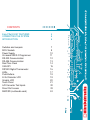
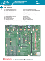
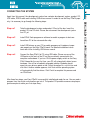
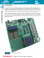
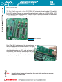
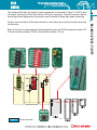
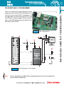
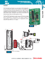
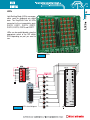
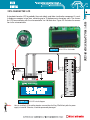
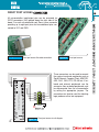
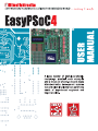
CONTENTS
Easy PSoC4 KEY FEATURES
CONNECTING THE SYSTEM
INTRODUCTION
4
5
6
Switches and Jumpers
MCU Sockets
Power Supply
On-board USB 2.0 Programmer
RS-232 Communication
RS-485 Communication
Real Time Clock
CAN-SPI
DS1820 Digital Thermometer
LEDs
Push-Buttons
2x16 Character LCD
Graphic LCD
Touch Panel
A/D Converter Test Inputs
Direct Port Access
MMC/SD (multimedia card)
7
8
10
11
12
13
14
15
16
17
18
19
20
21
22
23
24
4
EASY PSOC4
KEY FEATURES
1. External power supply 8v- 16v AC/DC;
2. On-board USB 2.0 programmer circuit;
13. MCU socket for additional MCU cards;
14. DIP switch SW1 to SW4 used for enabling/disabling on
3.
4.
5.
6.
7.
8.
9.
10.
11.
15.
16.
17.
18.
19.
20.
21.
22.
RS-232 communication circuit;
RS-485 communication circuit;
Real time clock circuit;
CAN-SPI circuit (Controller Area Network);
DS1820 temperature sensor circuit;
LCD 2x16 connector;
LCD contrast potentiometer;
A/D converter test inputs;
48-pin PSOC card with SMD CY8C27643-24PVXI chip;
12. MCU sockets;
board components;
Direct port access;
LEDs showing logical states of MCU pins;
Reset push button;
Push buttons;
GLCD connector;
Touch panel connector;
GLCD contrast potentiometer;
Touch panel controller; and
23. MMC/SD multimedia card slot.
Apart from this manual, the development system box contains development system, product CD,
USB cable, RS232 cable and Installing USB drivers manual. In order to use the Easy PSoC4 properly, it is necessary to go through the following steps:
Step no.1
Take the development system and product CD out of the box. Insert the
product CD into CD drive. Please, do not connect the development system
to a PC yet.
Step no.2
Install PSoC flash programmer software to enable a program to be transferred from PC to the microcontroller chip.
Step no.3
Install USB drivers on your PC to enable programmer's hardware to operate properly on the Easy PSoC4 board. For detailed installation instructions refer to the Installing USB drivers manual.
Step no.4
Connect the Easy PSoC4 to PC using USB cable. Please use one of the
USB ports on the back of the PC as they are directly connected to the
computer motherboard. If you turn ON the power supply switch on the Easy
PSoC4 board for the very first time, your PC will automatically detect a new
hardware. You will be immediately prompted whether Windows should
search for new drivers update or not. Select the option No, not this time and
click Next. Another window appears, click Next and the operating system
will automatically find the drivers. Click Finish to complete this process and
run PSoCflash.
After these four steps, your Easy PSoC4 is successfully installed and ready for use. You can read a
program from the chip or write another one into it. The product CD provides numerous simple program examples to make your first steps Easy...
5
CONNECTING THE SYSTEM
CONNECTING THE SYSTEM
INTRODUCTION
6
INTRODUCTION
The Easy PSoC4 is a full-featured development system for Cypress PSoC microcontrollers. It is
designed to allow students and engineers to easily test and explore the capabilities of PSoC microcontrollers. It also allows PSoC microcontrollers to be interfaced with external circuits and a broad
range of peripheral devices. The user can therefore concentrate on software development only.
Figure 1 illustrates the development system. There are identification marks next to each component
on a silkscreen, both on the top and bottom. These marks describe connection to the microcontroller, operation modes and provide additional useful information so that there is almost no need for
additional schematics.
Figure 1
Easy PSoC4 development system
SWITCHES
The Easy PSoC4 development system features a number of peripheral devices. In order to enable
them before programming, the appropriate jumpers or switches have to be properly set. Switches
are mechanical devices used to establish or break connection between two contacts. The Easy
PSoC4 development system has four groups of switches.
Figure 2
DIP switch
DIP switch
DIP switch
DIP switch
SW1
SW2
SW3
SW4
Switch group SW4
Switches 1, 2, 3 and 4 are ON,
whereas 5, 6, 7 and 8 are OFF
is used to enable/disable RS-232, RS-485 and MMC-CS;
is used to enable/disable DS1820, CAN and SPI;
enable/disable I2C, RTC-INT and touch panel controller; and
enable/disable LEDs.
JUMPERS
Similarly, jumpers are used to break or establish connection between two points. Under the plastic
cover of a jumper, there is a metal contact which establishes connection when a jumper is placed
over two pins.
Jumper is commonly used as a selector between two possible connections via 3-pin connector. As
illustrated in Figure 3, the middle connector pin can be connected to the left or right pin, depending
on the jumper’s position.
Jumper is not
placed and
middle pin is
unconnected.
Figure 3
Jumper as a selector
Jumper is placed
on the right side
connecting middle
and right pin.
Jumper is placed
on the left side
connecting middle and left pin.
SWITCHES AND JUMPERS
7
MCU SOCKETS
8
MCU SOCKETS
The Easy PSoC4 comes with a 48-pin CY8C27643-24P microcontroller soldered on MCU card that
fits in DIP48 socket. The user can remove this card and insert another one in DIP48, DIP28, DIP20
or DIP8 packages with adequate pin-out. Wide MCU cards on which you can solder microcontrollers
in QFN, TQFP, SOIC and SSOP packages can be used as well.
Figure 4
MCU sockets
Easy PSoC MCU cards are used for microcontrollers
having no appropriate on-board DIP socket. For large
number of pins these microcontrollers have, they
should be soldered on an MCU card and placed in
DIMM socket. The advantage of the cards is that they
can be used for connecting microcontrollers in different packages using only one on-board socket.
Note:
Since all packages have parallel connections, there must not be more than one microcontroller on the board at a time.
All ports are connected to LEDs and push-buttons, which allows you to easily test and monitor digital pins state.
Some of the pins are connected to on-board peripherals such as DS1820 temperature sensor, RS232 communication module, RS-485 communication module, LCD, etc.
Figure 5
System connection
9
MCU SOCKETS
The microcontroller pins are routed to various peripherals as illustrated in Figure 5. All MCU ports
are directly connected to Direct Port Access 2x5(10-pin) connectors. These are normally used for
connecting external peripherals to the board, as well as points for digital logic probe connecting.
POWER SUPPLY
10
POWER SUPPLY
The Easy PSoC4 can use one out of two power supply sources - PC power supply over USB cable
(by default) or external power supply (external AC/DC power adapter). When using power supply
over USB cable, jumper J1 should be set in the right-hand position.
When using external power supply, the Easy PSoC4 board produces +5V using LM7805 voltage
regulator. The external power supply can be AC or DC, while its voltage ranges between 8 and 16V.
In this case, jumper J1 should be set in the left-hand position. Figure 7 illustrates USB and external
power supply circuit diagram.
Figure 6
Figure 7
Power supply
Power supply circuit diagram
J1 in the left-hand position:
system is powered from the
external AC/DC power adapter.
J1 in the right-hand position:
system is powered from PC
over USB cable.
ON-BOARD USB 2.0 PROGRAMMER
There is no need to use external equipment during
programming as the Easy PSoC4 development system has its own on-board USB 2.0 programmer. All
you need to do is to connect the system to PC using
the USB cable. Load your program into the microcontroller via the PSoCflash programming software supplied with the Easy PSoC4.
Figure 8
Figure 9
Note:
USB 2.0 programmer
USB 2.0 programmer circuit diagram
There is no need to reset MCU after programming because it will be automatically
reset the MCU automatically.
ON-BOARD USB 2.0 PROGRAMMER
11
RS-232 COMMUNICATION
12
RS-232 COMMUNICATION
RS-232 communication module enables point-to-point data transfer. It
is commonly used in data acquisition applications to transfer data
between the microcontroller and PC. Since the voltage levels of the
microcontroller and PC are not directly compatible with each other, a
level converter, such as MAX232, must be used. In order to provide
more flexible system, the microcontroller is connected to the MAX232
via first four switches of the DIP switch SW1. The first and third switch
are used to connect Rx and Tx lines with P0[0] and P0[1] pins, while
the second and fourth switch are used to connect these lines with P0[6]
and P0[7] pins.
Figure 10 RS-232 communication
Figure 11 RS-232 communication circuit diagram
RS-485 COMMUNICATION
Similarly, RS-485 communication module is commonly used for data
transfer between several microcontrollers. ADM485 interface transceiver
is used for transforming signal from microcontroller’s Rx and Tx lines in
to a differential signal on “+” and “-” output lines.
Figure 12 RS-485 communication
The Easy PSoC4 development system has one RS-485 communication device. In order to provide more
flexible system, the microcontroller is connected to the ADM485 via three switches (5, 6 and 7) of the
DIP switch SW1. These switches are used to connect Rt, Rx, and Tx microcontroller lines to RS-485.
Figure 13 RS-485 communication circuit diagram
RS-485 COMMUNICATION
13
REAL TIME CLOCK (RTC)
14
REAL TIME CLOCK (RTC)
Most hardware projects need a real time clock or delay source.
For this reason the Easy PSoC4 development system is provided
with the PCF8583P chip (clock/calendar with 240x8-bit RAM). It
uses I2C serial communication to exchange data with the microcontroller. Besides, it has one interrupt output. In order that
PCF8583P works properly, both interrupt and I2C communication
lines must be connected to the microcontroller using switches 1, 2
and 3 of the DIP switch SW3.
Figure 14 Real time clock
Figure 15 Real time clock circuit diagram
CAN-SPI
15
CAN-SPI
CAN (Controller Area Network) is a serial network initially designed for
the use in automotive industry, but has also become a very popular bus
in industrial automation and other applications as well. CAN is a network
established among microcontrollers. It is a two-wire, half-duplex, highspeed network system. Half-duplex means that the microcontroller can
send and receive data, but either operation at a time.
The Easy PSoC4 development system has one CAN communication
device. Microcontroller is connected to CAN controller through SPI
communication, so you just need to turn on the appropriate switches
of the DIP switch SW2 (3, 4, 5, 7 and 8).
Figure 16 CAN-SPI
Figure 17 CAN-SPI circuit diagram
DS1820 DIGITAL THERMOMETER
16
DS1820 DIGITAL THERMOMETER
The DS1820 digital thermometer is convenient for environmental
temperature measurement. It can measure temperature in the range
between -55Co and 125Co with +/-0.5Co accuracy. It must be properly placed in the 3-pin socket provided on the Easy PSoC4, as
marked on the board (see Figure 19). Otherwise, the DS1820 could
be permanently damaged.
DS1820 socket
Figure 18 DS1820 digital thermometer
Figure 19 DS1820 digital thermometer circuit diagram
LEDs
17
LEDS
Light Emitting Diode (LEDs) are components used for displaying pin digital
state. The EasyPSoC4 has 64 LEDs
connected to the microcontroller ports:
PORT0, PORT1, PORT2, PORT3,
PORT4, PORT5, PORT6 and PORT7.
LEDs can be enable/disable using the
appropriate switch of the DIP switch
SW4 depending on port you want to
use.
Figure 20 LEDs
Figure 21 LEDs circuit diagram
PUSH BUTTONS
The Easy PSoC4 has 64 push buttons which can be
used to change states of digital inputs on the
microcontroller ports. There is also one red pushbutton that acts as a RESET.
PUSH BUTTONS
18
Figure 23 illustrates connection between push buttons and PORT0 and PORT1 as well as reset button connection. There are six more ports not shown
on this circuit diagram, but connected to push buttons in the same way as PORT0 and PORT1.
Figure 22 Push buttons
Figure 23 Push buttons circuit diagram
2X16 CHARACTER LCD
A standard character LCD is probably the most widely used data visualization component. It usually displays messages in two lines, containing up to 16 alphanumeric characters each. The character LCD communicates with the microcontroller via 4-bit data bus. Figure 25 illustrates its connection to the microcontroller.
Figure 24 2x16 LCD in 4-bit mode
Figure 25 2x16 LCD circuit diagram
Note:
Have in mind that LCD should be placed or removed from the Easy PSoC4A only after the power
supply is turned off. Otherwise, it could be permanently damaged.
2X16 CHARACTER LCD
19
GRAPHIC LCD
20
GRAPHIC LCD
A graphic LCD (GLCD) provides an advanced method for displaying visual messages. While a character LCD can display
only alphanumeric characters, a GLCD can be used to display messages in the form of drawings and bitmaps. The
most commonly used graphic LCD has the screen resolution
of 128x64 pixels.
The GLCD contrast can be adjusted using the potentiometer P4
placed next to GLCD.
Figure 27 GLCD
Figure 26 GLCD contrast adjustment potentiometer
Figure 28 GLCD circuit diagram
Note:
Have in mind that GLCD should be placed or removed from the Easy PSoC4 development system only
after the power supply is turned off. Otherwise, it could be permanently damaged.
TOUCH PANEL
21
TOUCH PANEL
Touch panel is a thin self-adhesive, transparent panel
that could be placed over the screen of graphic LCD. It
consists of two separate foils which form a “sandwich”
structure. It is very sensitive to press so that even a soft
touch causes some changes on the output signal. It is
used in various user-friendly devices in combination with
graphic LCD. Connector CN4 enables this device to be
connected to on-board touch panel controller the active
part of which consists of 5 discrete transistors. Four
switches of the DIP switch SW3 enable or disable connection between this controller and P0[2], P0[3], P3[4]
and P3[4] pins.
Figure 29 Touch panel
Figure 30 Touch panel controller
Figure 31 Touch panel circuit diagram
A/D CONVERTER TEST INPUTS
22
A/D CONVERTER TEST INPUTS
A/D conversion has a wide range of applications. The microcontroller takes an analog signal from
its input pin and converts it into a digital value. Basically, it is possible to measure any analog signal that fits in the range acceptable by the microcontroller. As for the Easy PSoC4, this range is
between 0 and 5V.
The Easy PSoC4 development system has three
potentiometer used to adjust the level of analog signals in order to test the operation of analog-to-digital converter (ADC). The potentiometer outputs
have voltage in the range of 0-5V. These analog signals can be connected to three different analog
input pins simultaneously. Jumper groups J3, J4
and J5 are used for connecting potentiometer P1,
P2 and P3 to the appropriate MCU pins.
Figure 32 A/D converter test inputs
Figure 33 A/D converter test inputs circuit diagram
DIRECT PORT ACCESS CONNECTORS
All microcontroller input/output pins can be accessed via
IDC10 connectors (2x5) placed along the right side of the
board. For each microcontroller port there is one connector
providing up to eight port pins and two additional pins connected to VCC and GND.
Figure 35
Direct port access flat cable connection
Figure 34 Direct port access
These connectors can be used to connect
the system to external peripherals such as
Serial Ethernet, Compact Flash, MMC/SD,
ADC, DAC, CAN, RTC, RS-485 etc. If onboard and external peripherals use the
same pins then on-board peripherals must
be disconnected from the microcontroller
by setting the appropriate jumpers. The
connectors can also be used for attaching
logic probes or other test equipment.
Figure 36 Direct port access circuit diagram
DIRECT PORT ACCESS CONNECTORS
23
MULTIMEDIA CARD (MMC/SD)
24
MULTIMEDIA CARD (MMC/SD)
MMC card is used as a data storage media for portable devices. With MMC reader you can easily transfer data from MMC card to your PC. The microcontroller placed on the Easy PSoC4 communicates
with Multi Media Card via SPI communication.
Figure 37 MMC/SD (multimedia card)
To enable MMC card it is necessary to turn on switch 8 of the DIP switch SW1 and switches 6, 7
and 8 of the DIP switch SW2. In this way, MMC Chip Select line (MMC-CS) and SPI communication lines (SCK, MISO and MOSI) are connected with the microcontroller. The operating voltage of
the Easy PSoC4 is 5V DC, whereas that of MMC card is 3.3V DC. For this reason, there is an onboard voltage regulator provided with MMC card (MC33269DT-3.3). Data lines connecting the
microcontroller and MMC card must also be adjusted to 3.3V It is done using resistor voltage
dividers shown in Figure 38.
MULTIMEDIA CARD (MMC/SD)
25
Figure 38 MMC/SD (multimedia card) circuit diagram
EasyPSoC4
Expand your development
system with our extra
boards:
Package content:
Development system:
CD:
Cables:
Documentation:
EasyPSoC4 with CY8C27643-24P included
mikroE product CD with software
USB and RS-232 cable
User manual for EasyPSoC4, driver installation guide Installing
USB drivers
System specifications:
USB programmer:
Power supply:
Power consumption:
Size:
Weight:
mikroBuffer Board
USB type B
External AC/DC 8-16V
PC over USB cable (5V DC)
>100mA (depends on connected peripherals)
25 x 21cm (9,8 x 8,2 inch)
393g (0.866 lbs)
MikroDRIVE board
Empty MCU cards
MCU cards with soldered
microcontroller
... and many others. Please,
visit our website:
www.mikroe.com