1
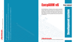
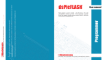
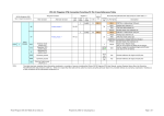
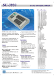
user's guide
to
MINI-32
The whole PIC32 development board fitted on DIP40 containing
powerful PIC32MX534F064H microcontroller. It’s the first
ever PIC32 chip on DIP40 socket, pin compatible with
PIC16F887 and PIC18(L)F45K20 microcontrollers!
TO OUR VALUED CUSTOMERS
I want to express my thanks to you for being interested in our products and for having
confidence in Mikroelektronika.
The primary aim of our company is to design and produce high quality electronic products
and to constantly improve the performance thereof in order to better suit your needs.
Nebojsa Matic
General Manager
The Microchip, Atmel, NXP and CYPRESS name, logo and products names are trademarks of Microchip, Atmel, NXP and CYPRESS Inc. in the U.S.A and other countries.
Table of Contents
Introduction to MINI-32
4
Key features
4
System Specification
5
1. Programming with bootloader
6
step 1 – Connecting MINI-32 6
step 2 – Browsing for .hex file 7
step 3 – Select .hex file 7
step 4 – .hex file uploading
8
step 5 – Finish upload
9
2. Schematic
10
3. Dimensions
11
4. Pinout
12
Page 3
Introduction to MINI-32
Key features
01 Reset button
02 DATA LED (connected on RD6)
02
01
03
03 STAT LED (connected on RG6)
06
05
04 POWER supply LED
04
07
05 Microcontroller PIC32MX534F064H
06 Quartz-crystal oscillator
07 USB MINIB connector
Miniature and powerful development tool designed to work as stand alone device or as MCU in DIP40 socket.
MINI-32 comes with preinstalled bootloader so it is not necessary to have external programmer. If there is need for
external programmer (mikroProg) attach it to MINI-32 via pads marked with RB6 (PGC), RB7 (PGD) and MCLR.
Page 4
System Specification
power supply
3.3V via pads or 5V via USB
power consumption
depends on MCU state (max current
into 3.3V pad is 300mA)
board dimensions
50.80 x 17.78mm (2 x 0.70“)
weight
~9g (0.02 lbs)
Page 5
1. Programming with bootloader
step 1 – Connecting MINI-32
For programming, microcontroller use bootloader program which
is preinstaled in to MCU memory. To transfer .hex file from a PC to
MCU you need bootloader software (mikroBootloader USB HID)
which can be downloaded from:
http://www.mikroe.com/eng/products/view/711/
mini-32-board/
01
02
After software is downloaded unzip it to desired location and
start mikroBootloader USB HID software.
Figure 1-1: mikroBootloader USB HID
01 Connect MINI-32 board with a PC via USB cable and USB icon
will turn red
02 Whitin 5s click on Connect button
Page 6
step 2 – Browsing for .hex file
step 3 – Select .hex file
MINI-32
01
01
01
Figure 1-2: Browse for HEX
Figure 1-3: Selecting HEX
01 Click on Browse for HEX button
01 Select .hex file via open window
02 Click on Open button
Page 7
step 4 – .hex file uploading
MINI-32
MINI-32
01
01
Figure 1-4: Begin uploading
Figure 1-5: Progress bar
01 To start .hex file uploading click on Begin uploading button
01 You can monitor .hex file uploading via progress bar
Page 8
step 5 – Finish upload
01
Figure 1-6: Restarting MCU
Figure 1-7: mikroBootloader ready for next job
01 To finish uploading click on OK button
Page 9
2. Schematic
VCC-3.3
VCC-3.3
RB8
RD4
RD5
RB9
RD11
RB0
RB1
RB4
RB5
MCLR
C2
100nF
VOUT
E2
REG1
3
2
1
VCC-USB
VIN
E1
MC33269DT-3.3
VCAP
C1
100nF
CN2
10uF
VCAP
VCC-3.3
RE1
RE0
RG6
RD0
RB15
RB14
RF0
RF1
VCC-3.3
10uF
E3
10uF
VCC-3.3
RE5
MCLR
T1
SOSCI
SOSCO
C6
22pF
X2
32.768kHz
C5
22pF
VCC-3.3
RE6
RE7
RG6
RG7
RG8
MCLR
RG9
VSS
VDD
RB5
RB4
RB3
RB2
RB1
RB0
RD1
OSC1
C7
22pF
RB7
RB6
RD3
RD2
RD1
RD10
RD9
RD8
X1
8MHz
LD3
VCC-3.3
C8
R3
4K7
USBDP
USBDM
100nF
RG6
LD2
VCC-3.3
C3
R4
4K7
100nF
CN3
R2
100
RE7
RE6
RE5
RE4
RF4
RF5
RG8
RG7
RE3
RE2
C9
RD6
USB-DET
OSC2
22pF
R5
2K2
SOSCO
SOSCI
RD0
RD11
RD10
RD9
RD8
VSS
OSC2
PIC32MX534F064H OSC1
VDD
D+/RG2
D-/RG3
VUSB
VBUS
USB-ID
RB6
RB7
AVDD
AVSS
RB8
RB9
RB10
RB11
VSS
VDD
RB12
RB13
RB14
RB15
RF4
RESET
LD1
RF5
RE4
R1
10K
RE3
RE2
RE1
RE0
RF1
RF0
VDD
VCAP
RD7
RD6
RD5
RD4
RD3
RD2
VCC-3.3
VCC-3.3
CN1
Figure 2-1: Connection schematic
Page 10
R7
100K
USB-ID
USBDP
USBDM
GND 5
ID 4
D+ 3
D- 2
VBUS 1
USB MINIB
3. Dimensions
17.78mm (0.70")
50.80mm (2")
2.54mm (0.10")
Figure 3-1: Board dimensions
Page 11
4. Pinout
Pin functions
Analog I/O
Pin functions
MCLR
RB7
PGED2
AN5
RB5
RB6
PGEC2
AN4
RB4
RD3
SCL3/SDO3/U1TX
AN1/VREF-
RB1
RD2
SDA3/SDI3/U1RX
AN0/VREF+
RB0
RD1
SCK3/U1RTS
INT4
RD11
RD10
INT3
AN9
Digital I/O
Programming lines
RB9
RD9
INT2
RD5
RD8
RTCC/INT1
RD4
3.3V
3.3V Power supply
AN8/U5RX
RB8
GND
GND
3.3V Power supply
3.3V
RE7
GND
GND
RE6
C1TX
RF1
RE5
CAN
C1RX
RF0
RE4
RB14
RF4
U2RX
AN15
RB15
RF5
U2TX
INT0
RD0
RG8
SCL4/SDO2
SCK2
RG6
RG7
SDA4/SDI2
RE0
RE3
RE1
RE2
Analog Lines
Interrupt Lines
SPI Lines
Page 12
I2C Lines
SPI/UART
Digital I/O
AN14/U5TX
Digital I/O
I2C
UART
I2C / SPI
Digital I/O
UART lines
CAN lines
Notes:
Page 13
Notes:
Page 14
DISCLAIMER
All the products owned by MikroElektronika are protected by copyright law and international copyright treaty. Therefore, this manual is to be treated as any
other copyright material. No part of this manual, including product and software described herein, may be reproduced, stored in a retrieval system, translated or
transmitted in any form or by any means, without the prior written permission of MikroElektronika. The manual PDF edition can be printed for private or local
use, but not for distribution. Any modification of this manual is prohibited.
MikroElektronika provides this manual ‘as is’ without warranty of any kind, either expressed or implied, including, but not limited to, the implied warranties or
conditions of merchantability or fitness for a particular purpose.
MikroElektronika shall assume no responsibility or liability for any errors, omissions and inaccuracies that may appear in this manual. In no event shall MikroElektronika, its directors, officers, employees or distributors be liable for any indirect, specific, incidental or consequential damages (including damages for
loss of business profits and business information, business interruption or any other pecuniary loss) arising out of the use of this manual or product, even if
MikroElektronika has been advised of the possibility of such damages. MikroElektronika reserves the right to change information contained in this manual at
any time without prior notice, if necessary.
HIGH RISK ACTIVITIES
The products of MikroElektronika are not fault – tolerant nor designed, manufactured or intended for use or resale as on – line control equipment in hazardous
environments requiring fail – safe performance, such as in the operation of nuclear facilities, aircraft navigation or communication systems, air traffic control, direct life support machines or weapons systems in which the failure of Software could lead directly to death, personal injury or severe physical or environmental
damage (‘High Risk Activities’). MikroElektronika and its suppliers specifically disclaim any expressed or implied warranty of fitness for High Risk Activities.
TRADEMARKS
The Mikroelektronika name and logo, the Mikroelektronika logo, mikroC, mikroC PRO, mikroBasic, mikroBasic PRO, mikroPascal, mikroPascal PRO, AVRflash,
PICflash, dsPICprog, 18FJprog, PSOCprog, AVRprog, 8051prog, ARMflash, EasyPIC5, EasyPIC6, BigPIC5, BigPIC6, dsPIC PRO4, Easy8051B, EasyARM, EasyAVR5,
EasyAVR6, BigAVR2, EasydsPIC4A, EasyPSoC4, EasyVR Stamp LV18FJ, LV24-33A, LV32MX, PIC32MX4 MultiMedia Board, PICPLC16, PICPLC8 PICPLC4,
SmartGSM/GPRS, UNI-DS are trademarks of Mikroelektronika. All other trademarks mentioned herein are property of their respective companies.
All other product and corporate names appearing in this manual may or may not be registered trademarks or copyrights of their respective companies, and are
only used for identification or explanation and to the owners’ benefit, with no intent to infringe.
© Mikroelektronika™, 2011, All Rights Reserved.
Page 15
MINI-32
If you want to learn more about our products, please visit our website at www.mikroe.com
If you are experiencing some problems with any of our products or just need additional
information, please place your ticket at www.mikroe.com/en/support
If you have any questions, comments or business proposals,
do not hesitate to contact us at [email protected]