1
I
NAVAL POSTGRADUATE SCHOOL
Monterey
,
California
THESIS
I)£b7
PRELIMINARY DESIGN AND CYCLE VERIFICATION OF
A DIGITAL AUTOPILOT FOR AUTONOMOUS
UNDERWATER VEHICLES
by
Stephen W. Delaplane
March 19 88
Thesis Advisor:
A.J. Healey
Approved for public release; distribution is unlimited
T238806
REPORT DOCUMENTATION PAGE
REPORT SECURITY ClASSiFCATON
la.
RESTRICTIVE
lb
MARKINGS
UNCLASSIFIED
SECURITY CwASSiFCAT.ON AUTHORITY
2a
Approved for public release
Distribution is unlimited
DECASSiFiCA t ON DOWNGRADING SCHEDULE
2b
PERFORMING ORGANIZATION REPORT NUMBER(S)
4
^AME OF PERFORM'NG ORGANIZATION
6a
6b OFFICE
ADDRESS
6c.
(City,
(City,
State,
Naval Postgraduate School
69
and
ADDRESS
7b
8b OFFICE
(If
and
State,
(City.
ZIP Code)
93943-5000
Monterey, California
93943-5000
\AME OF FUNDING SPONSORING
ORGANIZATION
ADDRESS
8c.
NAME OF MONITORING ORGANIZATION
7a
and ZIP Code)
Stare,
Monterey, California
Ja.
SYMBOL
applicable)
Code
Naval Postgraduate School
MONITORING ORGANIZATION REPORT NUMBER(S)
5
(If
1
DISTRIBUTION. AVAILABILITY OF REPORT
3
SYMBOL
PROCUREMENT INSTRUMENT IDENTIFICATION NUMBER
9
applicable)
ZIP Code)
10.
SOURCE OF FUNDING NUM8ERS
PROGRAM
PROJECT
TASK
WORK
ELEMENT NO
NO
NO
ACCESSION NO
UNIT
TITLE (Include Security Classification)
1
PRELIMINARY DESIGN AND CYCLE VERIFICATION OF A DIGITAL AUTOPILOT FOR
AUTONOMOUS UNDERWATER VEHICLES
PERSONAL AUTHOR(S)
12
Delaplane, Stephen W.
13a
TYPE OF REPORT
13b
Master's Thesis
TIME COVERED
CROM
DATE OF REPORT
14
TO
(Year,
Month, Day)
15
PAGE COUNT
69
19??, March
SUPPLEMENTARY NOTATION
16
The views expressed in this thesis are those of the author and do not reflect the official
policy or position of the Department of Defense or the U.S. Government.
COSATI CODES
17
FIELD
GROUP
ABSTRACT (Continue on
19
18
reverse
if
SUBJECT TERMS (Continue on reverse
if
necessary and identify by block number)
Digital Autopilot for Autonomous Underwater
Vehicles; Design
SUB-GROUP
necessary
and
identify by block
number)
Autonomous Underwater Vehicles (AUV's) are being considered for a diverThey protend the advantages of cost effective
sity of U.S. Navy missions.
fleet multiplication, minimal detectability and reduced risk to personnel
In response to the Department of the Navy and
and high-value fleet assets.
development by a number of public and
and
research
DARPA interests, AUV
The Naval Postin recent years.
intensified
has
organizations
private sector
which will
models
of
AUV
series
of
a
first
the
built
graduate School has now
This
technologies.
control
automated
evolving
be used as "test-beds" for
facility
on-site
an
install
to
efforts
initial
thesis documents the results of
for
autopilot
digital
model-based
of
a
development
to support the design and
interanalog-digital
and
PC/AT
IBM
an
Using
control of the NPS test vehicle.
facing, the development methodology has been implemented and verified by a
simplified model reference control program for AUV dive plane commands.
,
20
DISTRIBUTION /AVAILABILITY OF ABSTRACT
£}
22a
UNCLASSIFIED/UNLIMITED
21
SAME AS RPT
NAME OF RESPONSIBLE INDIVIDUAL
___
DD FORM
22b TELEPHONE (Include Area Code)
(408)
A.J. Healev
1473, 84
mar
ABSTRACT SECURITY CLASSIFICATION
Unclassified
Q DTlC USERS
83
APR
edition
All
may be used
until
exhausted
other editions are obsolete
.:2c
OFFICE
Code
646-2586
SECURITY CLASSIFICA
ft
U.S.
SYMBOL
6
9Hy
ON OF
Government
THIS
Printing Office
UNCLASSIFIED
PAGE
1996—606-2*.
Approved for public release; distribution is unlimited
Preliminary Design and Cycle Verification of a Digital
Autopilot for Autonomous Underwater Vehicles
by
Stephen W. Delaplane
Commander, United States Navy
B.S., Purdue University, 1969
B.S., Old Dominion University, 1978
Submitted in partial fulfillment of the
requirements for the degree of
MASTER OF SCIENCE IN MECHANICAL ENGINEERING
from the
NAVAL POSTGRADUATE SCHOOL
March 1988
ABSTRACT
Autonomous Underwater Vehicles (AUV's) are being
considered for a diversity of U.S. Navy missions.
They
protend the advantages of cost effective fleet multiplication, minimal detectability, and reduced risk to personnel
and high-value fleet assets.
In response to the Department
of the Navy and DARPA interests, AUV research and
development by a number of public and private sector
organizations has intensified in recent years.
The Naval
Postgraduate School has now built the first of a series of
AUV models which will be used as "test-beds" for evolving
automated control technologies.
This thesis documents the
results of initial efforts to install an on-site facility to
support the design and development of a model-based digital
autopilot for control of the NPS test vehicle.
Using an IBM
PC/AT and analog-digital interfacing, the development
methodology has been implemented and verified by a
simplified model reference control program for AUV dive
plane commands.
111
TABLE OF CONTENTS
I.
II.
INTRODUCTION
A.
BACKGROUND
1
B.
RESEARCH OBJECTIVES
2
EQUIPMENT DESCRIPTION, APPLICATION AND
PROCEDURAL DOCUMENTATION
4
B.
MICROCOMPUTER DESCRIPTION
5
C.
SIGNAL PROCESSING:
INTERFACE
D.
E.
F.
IV.
4
THE DESIGN AND CONTROL PROGRAM DEVELOPMENT
PROCESS:
AN OVERVIEW
A.
III.
1
ANALOG-DIGITAL
7
SOFTWARE:
INTERFACING, ANALYSIS AND
PROGRAMMING
9
DOCUMENTATION AND CONFIGURATION FOR
AUV DATA ACQUISITION
11
DOCUMENTATION AND CONFIGURATION FOR
AUV CONTROL
26
PROGRAMMING VERIFICATION
31
A.
PROGRAM PERSPECTIVE AND DESIGN
31
B.
PROGRAM IMPLEMENTATION
33
C.
PROGRAM VERIFICATION
39
D.
PROGRAM DOCUMENTATION
39
SUMMARY, CONCLUSIONS, AND RECOMMENDATIONS
44
LISTING OF CONTROL PROGRAM CODE
46
APPENDIX:
LIST OF REFERENCES
60
INITIAL DISTRIBUTION LIST
61
IV
1
LIST OF FIGURES
2
Phases of Program Development
.
6
2.2
System Configuration for Data Acquisition
12
2.3
Terminal Board Configuration for Data
Acquisition
14
2.4
DT/NOTEBOOK Main Menu
15
2.5
DT/NOTEBOOK Data Acquisition Process
Flowchart
17
2.6
DT/NOTEBOOK SETUP Command Menu
18
2.7
DT/NOTEBOOK NORMAL Mode Menu
18
2.8
DT/NOTEBOOK Channel
1
Configuration
21
2.9
DT/NOTEBOOK Channel
2
Configuration
21
2.10
DT/NOTEBOOK Channel
3
Configuration
22
2.11
DT/NOTEBOOK Channel
4
Configuration
22
2.12
DT/NOTEBOOK Channel
5
Configuration
23
2.13
DT/NOTEBOOK Data Files Setup
23
2.14
DT/NOTEBOOK Window Setup Configuration
25
2.15
DT/NOTEBOOK Trace Setup Configuration
25
2.16
System Configuration for Real-time
AUV Control
27
Terminal Board Configuration for
Real-time Control
28
System Configuration for Simulation of
Real-time AUV Control
30
3.1
Closed Loop Control Program Flow Chart
35
3.2
Program Cycle Time Trace at
Trigger Rate
40
2
.
17
2.18
'
8
Hz
3.3
3.4
Program Cycle Time Trace at 12 Hz
Trigger Rate
41
Program Cycle Time Trace at
Trigger Rate
42
VI
2
Hz
I.
INTRODUCTION
BACKGROUND
A.
The concept of a hierarchical automated intelligent
controller, or autopilot, as a state-of-the-art design
methodology is clearly evident from the proceedings of [Ref.
1]
.
As a part of an inter-disciplinary research program,
the Naval Postgraduate School is investigating many facets
of automated control technologies for underwater vehicles.
One of the objectives of this program has been to develop
operating "test-bed" vehicles and the facilities for
developing and evaluating real-time control systems.
In support of this objective, recent studies have led to
the development of a model-referenced control methodology.
Using the equations of motion for a vehicle of known
hydrodynamic characteristics, computer simulation was used
to develop the command generation logic, the design of a
model following autopilot and evaluate the performance of
the selected AUV computer model [Ref. 2].
Based on this vehicle's characteristics, subsequent
research led to the design and construction of the first of
a
series of operational AUV models which will be used to
evaluate evolving automated control technologies [Ref. 3],
This model was used to develop a technique for the
identification of discrete transfer function relationships.
.
In-water tank tests were conducted for maneuvers in the
vertical plane and from these, data was acquired
compared with the computer model simulation.
and
A system
transfer function relating dive plane commands to vehicle
response was then determined.
RESEARCH OBJECTIVES
B.
The focus of this research has been to implement a
microcomputer based capability to support AUV data
acquisition, vehicle response and transfer function
identification, and the development of real time digital
control programming.
Specific objectives included:
1.
The acquisition and integration of available
hardware and software.
2.
The documentation of specific implementations and
configurations used for the various phases of
program development to date.
3
The development of a high-level language program
for real-time control of the AUV test vehicle
dive plane maneuvering based on the methodology
and results of the research reported [Refs. 2,3].
This program would affirm the on-site development
procedure and identify insufficiencies or
incompatibilities which would need to be
resolved to support future research.
This thesis documents the accomplishment of these
objectives.
The integration of hardware and software are
discussed and evaluate in the overall perspective of the
program development process.
verified.
A program was developed and
This control program was written in Turbo Pascal
and processes three analog sensor signals and issues a
digital diveplane command.
The development procedure has
been verified, however certain shortcomings in multi-channel
signal processing and software compatability are discussed.
II.
A.
EQUIPMENT DESCRIPTION, APPLICATION AND
PROCEDURAL DOCUMENTATION
THE DESIGN AND CONTROL PROGRAM DEVELOPMENT PROCESS:
AN OVERVIEW
The development of real-time autonomous control programs
is a dynamic and evolutionary process.
It is the link
between computer simulations of the systems and the
implementation of controllers to achieve desired performance
of these entities in the real-world.
are exceedingly complex.
Autonomous controllers
In the early stages of controller
development, software implementations operating in
micro-computers which interface the device afford an
opportunity for verification and optimization of design
methodology and parameters.
Once designs have been
evaluated, the design logic is then implemented in an
onboard controller.
In this final implementation, much of
the control program coding will have been replaced by
functionally equivalent micro-electronic devices which
permit economies in size and power as well as flexibility of
application.
The remaining control logic is micro-coded
and programmed on micro electronic storage devices.
A principal objective of this research was the
integration of available software and hardware to support
the various activities in control program development for
the AUV.
These activities fall into three broad categories:
Data Acquisition, Data Analysis, and Design and
Implementation of real-time control programs.
-
Data Acquisition involves the assimilation of vehicle
parameters and responses to known inputs under
controlled conditions.
-
Data Analysis involves the analysis of vehicle
performance data for the purpose of extrapolating
quantitative relationships between input commands and
vehicle responses. These relationships are then
reflected as gain factors in transfer functions which
describe the AUV behavior or state.
-
Design and Implementation of real-time control programs
entails the representation of controller logic in
programming code. This software operates in a
micro-computer suitably interfaced with the AUV to
permit the sampling of vehicle sensor data and to issue
appropriate commands.
This chapter summarizes the specifications of the
hardware and the software utilized to support these phases
in the research reported herein.
The phases and application
of these resources are depicted in Figure 2.1.
Concluding
sections of this chapter document specific configurations
and commentary which supplement manufacturer's technical
reference materials with regard to this research
application.
Comments regarding the performance and
suitability of these resources are reported in Chapter IV.
B.
MICROCOMPUTER DESCRIPTION
An IBM PC/AT (compatible) microcomputer was acquired for
this and future research.
MHz and with
or
1
This computer operates at
wait states.
6
or 10
An Intel 80286
microprocessor and an 80287 math co-processor were
installed.
The Random Access Memory (RAM)
is expandable
DATA ACQUISITION
DATA ANALYSIS
&
AUV SYSTEMS IDENTIFICATION
DESIGN, TEST,
EVALUATE HIGH-LEVEL
LANGUAGE CONTROL
PROGRAM
AUV
AUTOPILOT
ONBOARD IMPLEMENTATION
OPERATING SOFTWARE
"FIRMWARE"
MICROELECTRONICS
Figure 2.1
Phases of Program Development
from its current size of 640 Kbytes.
Installed floppy disk
drives include a 1.2M byte (high density) and 360K byte
floppy disk drives are installed.
The floppy disk
controller has the capability of controlling an additional
3.5 inch disk drive as well.
A 40M byte hard disk is also
installed.
C.
SIGNAL PROCESSING:
ANALOG- DIGITAL INTERFACE
Interfacing the micro-computer and the AUV is critical
to the program development process.
At this interface
analog AUV sensor signals are digitized for the computer
control program through an A/D conversion process.
Similarly, digitized command signals are converted to analog
equivalent signals by D/A conversion processing prior to
transmission to the AUV analog servo-control components.
The A/D signal processing was utilized exclusively during
AUV test trials for data acquisition.
Both modes of signal
processing were utilized in development of the control
program.
A detailed description of the configurations
during these phases are reported later in this chapter.
This section concludes with a description of the devices
used to achieve the analog-digital signal processing
interface and a summary of the technical specifications
detailed in the manufacturer's literature [Ref. 4].
Interfacing the AUV and the computer was accomplished
using two modern device boards.
The model DT 2801-A is a
programmable, single board, analog and digital I/O signal
This board is one of a series designed for the
processor.
IBM Personal Computers and was installed into one of the
backplane slots on the computer's mother board.
Once
installed, a multi-pin connector, accessible at the back of
the computer, facilitates connecting the DT 2801-A to an
external screw terminal panel, the DT 707, by a ribbon cable
and connector.
The DT
7 07
was used to connect AUV sensor
inputs, the command output, and an external trigger signal.
Specific configurations are discussed later in this chapter.
The following summarizes detailed technical
specifications contained in the manufacturer's product
literature [Ref. 4].
DT 2801-A Digital and Analog Signal Processor
1.
This device supports A/D conversion processing on
8
differential analog or 16 single ended, unipolar or bipolar,
input channels with 12-bit resolution.
are
2
Similarly, there
D/A conversion channels for processing output signals.
Software selectable gains accommodate a range of input
signals.
With 12-bit resolution and programmable gains it
is possible to achieve a conversion accuracy on the order of
+/- 0.03% of Full Scale Reading (FSR)
.
An onboard clock can
be used to initiate data conversion events for periods of
2.5 microseconds to 0.819 seconds in 1.25 microsecond
increments.
For more precise initiation of data conversion
events or to synchronize with control program timing, an
external trigger input is also available.
Throughput, the
.
time to execute one complete read or write cycle, of 27.5
KHz can be achieved under Direct Memory Access (DMA)
procedures.
The onboard processor is programmable by any
language that can access I/O registers of the IBM PC. Also,
pre-programmed, user callable, subroutines are available for
use with this device under the product name PCLAB.
[Ref.
5]
Similarly, a complete Data Acquisition software package,
DT/NOTEBOOK is also available.
[Ref.
These products
6]
were used in this research and are described in later
sections of this chapter and in chapter
2
3.
DT 707 Screw Terminal Panel
.
This unit along with the ribbon cable and connector
facilitate connection of I/O channels for analog to digital
signal process and digital to digital signal processing.
There are also terminal connections for external trigger
signal sources.
D.
SOFTWARE INTERFACING, ANALYSIS AND PROGRAMMING
Data Acquisition
1.
This phase of program development was greatly
facilitated by the use of a software program, DT/NOTEBOOK.
[Ref.
6]
The details of its employment and the system
configuration are reported in the next section.
2
Data Analysis and AUV System Identification
Assuring the capability to analyze vehicle test data
and identify discrete transfer function relationships was a
This analysis was
principal objective of this research.
accomplished and reported in [Ref.
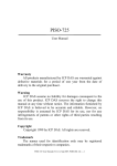
called MATRIXx [Ref.
7]
3]
using a CAD Program
This program affords an extensive
set of design and analysis functions for classical and
state-space control.
It also provides a state-of-the-art
matrix analysis and graphical display capability.
3
Control Programming Utilities and Language
.
PC LAB consists of a library of low level routines
which are callable as procedures, functions or subroutines
in the following high level programming languages:
FORTRAN, Pascal, Turbo Pascal and C.
BASIC,
These routines include
single and multiple channel, or block, A/D and D/A
conversion, with buffered storage and DMA control options.
[Ref.
5]
It should be noted that multiplexing of selected
inputs using multiple channel, or block read, procedures is
on the order of microseconds when using the DT 2801-A signal
processing board.
[Ref.
4]
This sample interval was
considered to adequately simulate "instantaneous" sampling
of discrete vehicle parameters.
Another signal processor,
the DT 2818, is advertised to have "simultaneous sample and
hold" and multiplexes the input channels on the order of
nanoseconds.
This processor may have application in future
program development.
The control program reported in Chapter III was
written in Turbo Pascal and compiled to run under either PC
DOS or MS DOS operation systems.
10
[Ref.
8]
The facility of
the Turbo Pascal program development environment, the
intrinsic ability to manipulate text and data, the screen
graphics capabilities and recursive procedure calls were
strong considerations in the selection of this programming
language.
Discussion regarding use of specific PC LAB
routines and Turbo Pascal programming are presented in
Chapter III.
E.
DOCUMENTATION AND CONFIGURATION FOR AUV DATA ACQUISITION
This section documents the configuration of hardware and
provides commentary on the application of the DT/NOTEBOOK
program as it was used in acquiring data during actual tank
testing.
Figure 2.2 depicts the system configuration for
this phase of the research.
The DT/NOTEBOOK is a menu-driven data acquisition
program with options for data analysis.
(These options were
not used, however, in favor of the more powerful CAD program
MATRIXx previously discussed.)
The DT/NOTEBOOK program
affords a high level user interface with the DT 2801-A
signal processor and was used exclusively for AUV data
acquisition during tank testing.
The comments in this
section are intended to supplement the excellent tutorial
and user documentation provided with the DT/NOTEBOOK program
[Ref.
6]
with comments specific to this research.
During the AUV trials three channels of analog data were
sampled, digitized and stored for subsequent analysis.
three channels of sensor data consisted of depth, from a
11
The
1
c
o
•H
•H
l/i
•H
P
cr
u
<
03
M
a
o
m
C
o
•H
U
rfl
M
3
en
H
c
o
u
e
a)
-u
en
>i
en
X
o
o
D 6- OQ
u
a.
H
z «t
o
o -v
oaz
^
o o- H
a
a xa
OQ
X
(N
OS
Ed
E-
(N
U
3
H-
H-t
-K
12
transducer output; speed from a dynamic head transducer, and
pitchrate from a pitchrate gyro.
The configuration of the
DT 2801-A/DT 707 terminal panel interface with the AUV is
shown in Figure 2.3.
DT/NOTEBOOK uses a hierarchical menu concept much like
Lotus 123.
Menu selections are made by either moving the
highlighted input box with the cursor keys until it
"captures" the desired option and then pressing the <Enter>
or by merely pressing the key corresponding to the first
letter of the command name.
As successive options are made,
the user moves deeper into the menu hierarchy.
At each
level, a new menu of commands or data input options is
presented.
Pressing the <EXC> key moves the user back out
of the menu one level at a time.
Figure 2.4 illustrates the Main Menu.
contained on 12 disks.
The program is
The first of these is a "Key Disk"
which must be inserted in Drive A during installation and
whenever the program is first executed.
Installation
instructions are clear and specific and are selected from
the Main Menu using the INSTALL command.
During the
installation, two directories are created on the hard disk:
Drivers and Notebook.
Once the installation has been
completed, the user merely locates himself in the Notebook
directory, inserts the Master Key in Drive A, and enters
"nb" from the keyboard.
The program then displays the Main
13
MICROCOMPUTER RIBBON CONNECTION
DIGITAL
DIGITAL I/O
PORT
PORT
I
&nO
GNO
O
©
Bit $
BIT 6
©
I/O
©
ANALOG INPUT
AUV PITCHRATE
:
© ANALOG
'
BIT
BiT
I
3
D
&xO
&ND
©
BITS
&MO
BiT
BIT *
D
ANALOG INPUT
TRANSMITTER DIVEPLANE
COMMAND
D&NO
D GNO
BiT i
BiT C
O CnO
O&MD
Bit 7
BIT 7
3
INPUT
SPEED
ANALOG INPUT
AUV DEPTH
O GMO
BIT
AUV
I
4x0
©
©
©
©
©
©
©
©
&NO
i*0
O&mO
CxO
E*T
EXT
Ci-K
T»i«
©
O&MO
Figure 2.3
cn.4
Terminal Board Configuration for
Data Acquisition
14
CM •
MT
S
Cm 4
S
i»0
S
4N0
A
WHO
5i«
i
CUT
D/a
u><0
i
SETUP GO ANALYZE CURVE-FIT FFT
Perform data acquisition / control
INSTALL
PROGRAM
QUIT
DT/NOTEBODK
Figure 2.4
Menu of selections.
DT/NOTEBOOK Main Menu
The Master Key disk may then be removed
and is not needed again during the current program session.
The QUIT command exits the program and returns to the
Disk Operating System (DOS)
.
The PROGRAM command allows the
user to depart the Notebook program and execute programming
in DOS and then return to Notebook without having to "re-
boot" the program with the Master Key disk.
This feature
operates must like a programmable interrupt in that the
"status" of Notebook is saved for the period that the user
is in DOS and is restored upon returning to the Notebook
program.
The CURVE FIT and FFT commands are intrinsic program
capabilities for curve fitting and fast fourier transform
operations on data files.
The ANALYSIS command permits the
user to call an external analysis program of the user's
choosing.
(Lotus 123 was used as an example in the
15
documentation.)
This permits analysis and graphical
representation from within the Notebook program.
features were not used in this research.
These
Acquired data were
analyzed and graphed using MATRIXx as a stand-alone program.
The remainder of this sub-section describes the data
acquisition process used extensively in this research and
which was executed using the SETUP and GO commands from the
Main Menu.
Figure 2.5 depicts a flowchart of the system
configuration "setup" and data acquisition initiation, or
"Go," process.
It should be noted that once a suitable
configuration has been achieved it can be saved as a setup
file and recalled for future use.
There were several such
files saves in this research, however the file named
AUVSETUP was used almost exclusively and its configuration
is reflected in the figures referenced in the sub-section.
From the Main Menu, selecting the SETUP command results
in the presentation of five configuration commands shown in
Figure 2.6.
The CHANNELS command allows the user to configure the
software to the physical hardware connections of the DT
2801-A/DT 707 interface.
The user is first asked to choose
between NORMAL or HIGH SPEED data acquisition.
command was used throughout this research.
The NORMAL
The HIGH SPEED
option was not needed for the sampling required in this
research.
This mode places restrictions on data display,
16
CONNECT AUV SENSORS
TERMNAL
TO DT 707
*
'80* COflHAND
ENTER
BOARD
1
\
RELEASE AUV TO COMMENCE
CONNECT AUV TRANSMITTER
TRIAL
RUN
COMMAND INPUT SI6NALS
TO DT 707 TERMINAL
BOARD
PRESS "ANYKEY" TO START
DT/NOTEBOOK DATA
ACQUISITION
'
'
i
INTER DT/NOTEBOOK PROSRAN
t
RECALL PREVIOUS SETUP
FILE
EVALUATE DATA DISPLAY
OR
EXECUTE SETUP ROUTINE
TO DECLARE HARDWARE
CONFISURATION, DISPLAY
ANI
PRESS <ESC>
FILE SPECIFICATIONS
SELECT SETUP/FILES
ENTER
A
:
NEW DATA FILE
NAME FOR THE NEXT AUV
TRIAL RUN.
PRESS <ESC>
Figure 2.5
TWICE.
DT/NOTEBOOK Data Acquisition Process
Flowchart
17
8
CHANNELS
DISPLAY
FILES
SAVE/RECALL
VERIFY
Initialize data acquisition / control
Figure 2.6
i.urrt'nt
/jIul-:
DT/NOTEBOOK SETUP Command Menu
Anal
'."J
[iipi.it.
NOPMAL DATA
Numper of Channels
Cur rent Channel Is
In or n. m]
Channel Type
Channel Name
AC C'U
Inter face Device
C
hanne
f
er
'ji
Number
CO.
.
T
I
ON
/
GNTPOL SCTUF
c
1
Analog Input
DT2801A
15]
jK
1
V
0.500
500
1 .
ze
I'c>-»
Numoer <-,f Iterations
Numper of Stages CI.. 4]
1
1
Sampling Pate, Hr
Stage Duration, sec. CO. 0.
OE+083
Start /Stop Method
Trigqer channel
Trigger Pattern to AND CO.. 2551
Trigger Pattern to »0R CO.. 2553
Time Delay, sec. CO. 0. . 1. OE+083
.
Figure 2.7
I
0:
1
Input kanqe
Scale factor
Offset Constant
E"uf
T.
.
i
Interlace
I
1
.
10.000
20.OO0
Normal
t
O
0.O0O
DT/NOTEBOOK NORMAL Mode Menu
18
memory requirements and data buffering and file creation
which must be considered if this mode is used.
Selecting the NORMAL command results in the presentation
of the NORMAL Mode Menu, Figure 2.7.
A list of "setup
conditions" is presented down the left side with a column of
cells for user entries to the right.
Entries are made
by-
using the cursor to "capture" the desired cell with the
highlighted input cell.
Configuration specifications are
input using appropriate keys which are "echoed" in the
Current Value cell in the upper left hand corner of the menu
Pressing ENTER or moving the input cell with the
display.
cursor key enters the configuration in the program.
The
program offers some specific options for various setup
conditions which are displayed by pressing Fl.
It should be
noted that the DT 2801-A can sample up to 16 input channels
(0
...
Number.
15)
and these are specified by Interface Channel
The user must recognize the distinction between the
"data channels" specified in the first four lines of the
menu and the interface channel.
The data channels are user
creations based upon the data requirements.
The interface
channels are physical input connections to the signal
processor.
In this research, data channel
1
was always configured
as TIME and used to record elapsed time for an event from
the DT 2801-A processor clock.
The remaining
4
data
channels were specified to receive sensor input signals.
19
Figures 2.8-2.12 illustrate these configuration
specifications.
The next SETUP command is FILES.
The option data files
are configured to meet user requirements.
Figure 2.13
illustrates a data file setup which was used for most of
this research.
emphasized.
There are two points which need to be
The first is that after each run, the user must
return to this menu and change the "Data File Name."
If
this is not done, NOTEBOOK will overwrite the new data into
the same file.
Secondly, the data field specification must
be specified to meet the input data file requirements of
MATRIXx if the acquired data are to be analyzed in this
program.
A machine executable data conversion program
(convdata.exe) was written to convert NOTEBOOK data into
MATRIXx acceptable data.
After gaining more familiarity
with both these programs, it was discovered that the data
conversion program was not necessary.
If properly specified
in the NOTEBOOK and MATRIXx, data can be used directly.
Future researchers should consider the experimental data
requirements and then consult the documentation of these
programs to effect the proper configuration.
One last documentation remark has to do with the file
naming convention used in this research.
Conforming to the
MS-DOW rules for naming files, data files for AUV trials
were named as the following example illustrates:
20
Current
Value:
1
NORMAL DATA ACQUISITION
Nuaber
Current
Channel
Channel
/
of Channel*
CONTROL SETUP
5
Channel(s) In or n..a)
1
Type
Naae
Ttae
TIME
For,,t
sssss.sss
BuffnrSlze
Nuaber of Iterations
Nuaber of Stages 1..4]
"048
1
(
Saapllng Rate, Hz
Stage Duration, aec.
j
[0.0..1 .OE
»08
)
Start/Stop Method
Trigger Channel
Trigger Pattern to AND (0..25S)
Trigger Pattern to XOR [0..255]
1
Tlae Delay, sec. 0.0.. 1.0E 08
Analog Trigger Value
Analog Trigger Polarity
Nusber of Saaples to Save (Pretrlgger)
(
Figure 2.8
Current
Value:
20.000
20.000
Noraal
]
0.000
0.000
High
DT/NOTEBOOK Channel
Configuration
1
'.'
NORMAL DATA ACQUISITION / CONTROL SETUP
Nuaber of Channels
5
Current Channel(s) (n or n..a]
2
Channel Type
Analog Input
Channel Naae
PITCH HATE
Interface Device
Q: DT2801A
Interface Channel Nuaber (0.15)
2
Input Range
Scaler' actor
Offset Constant
Buffer Size
Nuaber of Iterations
Nuaber of Stages (1..4)
qt.25 V
1000
0.000
2048
1
1
Saapllng Rate, Hz
Stage Duration, aec. (0.0..1.0E *08
)
Start/Stop Method
Trigger Channel
Trigger Pattern to AND (0..255)
Trigger Pattern to XOR 10. .255)
Tlae Delay, sec. (0.0..1.0E -08
Figure 2.9
20.000
20.000
Noraal
I
0.000
I
DT/NOTEBOOK Channel
21
2
Configuration
Current
Value:
NORMAL DATA ACQUISITION
Nuaber
Current
Channel
Channel
5
Channel(s) [n or
3
n..a)
Analog Input
Type
Nana
Interface Device
Interface Channel Nuaber
Input
DEPTH
DT2S01A
0:
(
15
6
1
qlO
Range
2048
1
1
Saapllng Rate. Hz
Stage Duration, sec. [0.0..1 .0E 08
1
Start/Stop Method
Trigger Channel
Trigger Pattern to AND (0.255)
Trigger Pattern to XOR 10. .255]
20.000
20.000
Noraal
1
0.000
Tlae Delay, sec. I0.0..1.0E*08)
Figure 2.10
DT/N0TEB00K Channel
Current Value:
Configuration
3
4
NORMAL DATA ACQUISITION
Nuaber
Current
Channel
Channel
V
1.000
0.000
Scale Factor
Offset Constant
Buffer Size
Nuaber of Iterations
Nuaber of Stages 11.4)
/
CONTROL SETUP
of Channels
5
Channel(s) In or n.a)
*
Type
N.ae
Interface Device
Interface Channel Nuaber {0.151
Analog Input
DIVE CMD
0:
DT2801A
8
ql.25 V
1.000
0.000
2048
Input Range
Scale Factor
Offset Constant
Buffer Size
Nuaber of Iterations
Nuaber of Stage* (1-4)
1
1
Saapllng Rate, Hz
Stage Duration, tec. [0.0..1.0E + 08]
Start/Stop Method
Trigger Channel
Trigger Pattern to AND (0..2551
Trigger Pattern to XOR (0..2S51
Tlae Delay, sec. [0.0..1.0E-08
Figure 2.11
CONTROL SETUP
/
of Channels
)
DT/NOTEBOOK Channel
22
20.000
20.000
Noraal
1
0.000
4
Configuration
Current Value:
5
NORMAL DATA ACQUISITION
Nuaber of Channels
Current Cbannel(s) [n or
Channel Type
Channel Naae
Interface Device
Interface Channel Nuaber
5
n,.a]
5
Analog Input
PITCH ANGLE
DT2301A
0:
(0..1S]
4
•
Range
Scale Factor
Offset Constant
Buffer Size
Nuaoer of Iterations
Nuaber of Stages 11. .4)
Input
Saapllng Rate. Hz
Stage Duration, sec.
Tlae Delay, sec.
Figure 2.12
Current Value:
(0
.0..
q
1
.
V
1
1.000
000
204!)
1
1
(0.0.. 1.0E»
Start/Stop Method
Trigger Channel
Trigger Pattern to AND
Trigger Pattern to XOR
CONTROL SETUP
/
08
20.000
20.000
Noraal
1
1
255)
10. .2551
•
1 08
(0.
0.000
)
DT/NOTEBOOK Channel
5
Configuration
1
FILES SETUP
Nuaber of Data Files (0..12)
Current Data File 11. .1J
Data File Naae
Storage Mode
Nuaber of Header Lines (0..4)
Header Line 1
Header Line 2
Header Line 3
Header Line 4
1
1
AV010915.DAT
ASCII Real
4
AUV SYSTEMS IDENTIFICATION DATA
9 JAN 1988
RUN 15
:
The tlae
The date
Nub. of Channels In File (0.100)
File Channel
5
Nuaber
Channel Nuaber
Channel Naae
Channel Units
ST1ME.
SDATE.
12
12
TIME PTCHRATE
Seconds
volts
Field Width (ASCII Files)
Declaal Places (ASCII Real Files)
Figure 2.13
Is
Is
3
4
3
5
4
DEPTH DIVE CMD PTCHANCL
volts
volts
VOLTS
12
12
12
12
12
4
4
4
4
4
DT/NOTEBOOK Data Files Setup
23
5
AV
01
09
15
DAT
denotes
denotes
denotes
denotes
was the
AV010915.DAT
AUV data acquired from NOTEBOOK
the month of the trial, i.e., January
the day of the month of the trial
the particular trial for the day
extension used for all data files.
Files which were converted by the data conversion program
for analysis with MATRIXx were named by the same convention
except "UV" was used for the first two characters.
Thus the
file UV010915.DAT would indicate that this is the data file
converted from AV010915.DAT for use with MATRIXx.
The next SETUP menu option is DISPLAY.
This command
specifies the setup for the real-time display of data as it
is being acquired.
This feature is most beneficial in
evaluating the quality of the data collected.
It should be
noted that in achieving a visual display the program invokes
a liberal "graphical license" and so the
displays afford a
relative measure and not an exact replication of the data
acquired.
The stored data file is unaltered by the display
configuration specification.
The DISPLAY command presents the user with two menus:
WINDOW SETUP and TRACE SETUP.
In these menus the user can
specify the number, size and type of the display windows and
the data trace characteristics.
There is considerable
flexibility and the program documentation should be
consulted to exploit this feature.
Figures 2.14 and 2.15
illustrate configurations used in this research to display
three windows and their respective traces.
24
Current
Value:
WINDOW SETUP
Nuaber of Windows (0..1S)
3
Window Nuaber
Left
Title
Title
Length of Tlae (X) Axis
X Tic Start Value
X Tic End Value
Nuaber of X Tics [0.11]
Y Tic Start Val
Y
0.100
0.950
0.300
PTCIinT V
Axis
X Axis
Figure 2.14
In
SBC.
2
1
0.1 50
Llalt. xO [0.0. .1.0)
Lower Llalt, yO [0.0. .1.0]
Kljht Llalt, xl [0.0.. 1.0)
Upper Llalt, yl [0.0. .1.0)
3
0.150
0.400
0.950
0.600
0.1 50
0.750
0.950
0.950
DVCMD
DEPTH i
TIMK/SEC TIME/SEC TIME/SEC
30.000
30.000
30.000
'
0.000
30.000
0.000
30.000
7
0.000
30.000
7
7
DT/NOTEBOOK Window Setup Configuration
Current Value:
4
TRACE SETUP
12
12
Nuaber of Traces [0..50]
Trace Nuaber
Window Nuaber [1..15J
4
Line Color
Line Type
Data Point Syabol
Y
Y
Y
Black
Solid
None
Channel Nuaber
Mlniaua Displayed Value
Maxiaua Displayed Value
Red
Trace Type
For Meters Only:
Nuaber of Declaal Places
For Type XY Only:
X Channel Nuaber
X Mlnlaua Displayed Value
X Maxiaua Displayed Value
None
Yellow
Solid
None
3
T vs. Y
None
5
4
-0.500
0.500
0.000
10.000
T vs. Y
4
2
White
Solid
Solid
2
-0.500
0.500
3
3
T
vs.
-10.000
10.000
T
Y
vs.
Y
'
Figure 2.15
12
3
0.000
10.000
3
0.000
10.000
3
3
4
3
0.000
10.000
0.000
10.000
DT/NOTEBOOK Trace Setup Configuration
25
.
The next SETUP is VERIFY.
Executing this command
displays a screen which reflects the configuration which a
user has specified.
This provides a good check of the
system setup.
The last SETUP command is SAVE/RECALL.
As the title
suggests this command allows the user to save a particular
configuration setup as a specific file or to recall such a
file for reuse.
Once a system configuration has been specified and the
AUV is connected to the DT 2801-A/DT 707 interface, actual
data acquisition is initiated by selecting the GO command
from the Main Menu.
In its default configuration, the
program will commence data acquisition as soon as GO is
selected.
However, a useful feature is the "Keystroke
Before Run" which is selectable in the INSTALL, OPTIONS
commands.
This delays the beginning of data acquisition
after GO is selected until "any other key" is depressed.
This feature was used throughout this research as it
permitted more precise control over the data acquisition
events
F.
DOCUMENTATION AND CONFIGURATION FOR AUV CONTROL
Figure 2.16 depicts the system configuration for control
of the AUV under high-level language control programming.
Figure 2.17 shows a schematic of the DT 707 terminal
connections.
Owing to the non-availability of the test tank
and suitable radio transmitter interface module to transmit
26
CO
<
z
u
•o-
Cd
CO
<
OS
O
CO X O X
Z E- CJ
OS
o
J-l
CxJ
-u
c
o
CO Cd CU .-.
CO 0.
Q
U
>
<
* * *
a.
z
CU
e
H
4J
I
r-i
(8
CJ
«
*U
J
..
CJ3
~
Cd
\
a
oJ
CO
CO
<
z
Ed
t-i
OS
Ed
1
UX
O os z
« 06 U O
QU
>* < «otto
00
O os
J Cd cm
H
ZZ
« <~ Q
I
H
JNO
<O
z
o
Cd
r-
H
OS tCd *-
os
Cd Cd
et-
Cd
O
<
H X Ed
stnaj
a.
Cd D
ft.
•
».
Z
x<ha
os z o
o
OH—X
o
—
ax
< CO
os z
H-.
«t
OS
t-
z
<4-i
za
<ZH
J
<£ =)
x cu
XH
> o =>
Mao
a.
Cd
a
M
O
C
H
-P
^
P
C7>
•H
4-1
z
~HO
co a a
C
o
u
e
CU
4-)
CO
>1
CO
VO
0)
p
en
•H
27
OK 3ITAL I/O
PORT
GNO
BIT
1
w.0
BIT
i
GmD
6<T
3
O&MO
BIT
©
©
<s
©
©
©
<s
txO
BITS
DGmO
Bit i
tNO
Bit 7
D
©
©
SnD
©
©
©
©
©
©
©
DIG ITAL I/O
MICROCOMPUTER RIBBON CONNECTION
PORT
1
BIT 9
&NC
BIT
1
OOO
BlT
D
I
GNO
kt
©
©
©
©
©
©
ANALOG INPUT
AUV PITCHRATE
S
BIT *
OC.MD
BIT 5
GNO
Bit &
D&MD
BIT 7
(ND
©
©
©
©
©
©
©
©
©
D6M0
©
©
% fc»0
©
©
Cm O
ANALOG INPUT
AUV SPEED
:
^
net
S
&n©
©
©
©
S6N0
SGuO
©
©
Cm
ANALOG INPUT
AUV DEITH
:
S&NO
5
«CT
l
T3
S &NO
5
GNO
©
CM
CHIS
7
CNO
A
D/A 8
CXIT
D/A
O&NO.
t»0
ft
©
ANALOG SIGNAL OUTPUT
AUV DIVEPLANE
COMMAND
©
©
Terminal Board Configuration for
Real-time Control
28
ft
Cm £
RET
* CNO
IS- ^©
L>
-©
Figure 2.17
©
©
WNO
AMPL0
Cl»*
]
•s
3
txO
©
:
3&NO
EXTERNAL TRIGGER
duo CONNECTION
CXT
©
S GnO
b
A
4NO
WNO
D-a
I
out
D/A
UNO
i
the generated dive plane command to the AUV, real-time
control was not accomplished in this research.
Figure 2.18
shows the system configuration used to simulate real-time
control configuration in the development and verification of
the control program.
Details of the program development and
verification are reported in Chapter III of this thesis.
29
1
i
i
1
t
o
<
OS
U Q Cd
ZZH
Cd < <
o a
a
o
<
<C
CxJ
z
u
H
cd
Cd
a. •»
co eu
i—
a.
cu
OQ
u
4J
c
o
u
>
D
<
1-4
*
CO
X
<
z
o
<
a
Ed
ZJ
Cd < a
C5 Z Cd
a o cd
J Cd O
CO
<f-M
zxaJ
3
U Cd f- Cu
6-
z
OX
I
CO
*
CO
*
a)
e
•H
4J
I
rH
(d
cu
>-
<
«—
><
1»
«
5
-J
a*
CO
a.
CO
1—
1-4
a "
^
4
Z
u
1—
CO
CO
Q
J
«C
z
o
I
1
c
o
•H
-P
M
J
J
*
VJ
ITJ
I—
a
e
H
CO
<
1
o
m
c
o
•H
-p
o
<
l-H
h-
a
«*.
U
O
J
«S
z
<
(0
CO
CO
cd I—
z
ax
o as z
oc Cd O
Cd
o
H
<
O >J o
Cd
OS 03 <
z
z
Ed
6z
z
o
Q CO o
5-1
P
CP
•H
*4-l
c
u
Cfa
e
c<a
cu
4J
W
l-l
>i
CO
00
o
o
CU
u
0Q
E- Cd
Cn
<H
O
oo
O Cu
h
os
xQ
o
»—
H
Cm
CQ
30
III.
PROGRAMMING VERIFICATION
This chapter reports on the final objective of this
thesis:
verification of I/O processing of analog and
digital signals under higher-level program control.
The
following sections discuss the design, implementation,
verification and documentation of this program.
A complete
and documented listing of the main program is contained the
Appendix.
A.
PROGRAM PERSPECTIVE AND DESIGN
The introduction of [Ref.
2]
presents a concise
description and illustration relating this concept to this
and other current research at the Naval Postgraduate School,
The theory of classical (closed loop) controllers as well
as modern state-space design of Digital Autopilots are
further discussed in [Refs. 10,11].
In its final
implementation, a digital autopilot will control all six
degrees of freedom of the AUV in the execution of a variety
of missions and in a diversity of operating environments.
The architecture of the autopilot will reflect extensive
functional modularity.
Under the supervisory control of an
"AUV Operating System," missions will be executed as a
sequence of tasks compiled and ordered by the onboard
planning logic and knowledge database.
Similarly,
completion of these tasks will reflect the compilation and
31
execution of functional capabilities in sequence or in
parallel under the control of a lower-level operating
system.
These functional capabilities may well be
implemented as multi-processors each reflecting a
hierarchical organization specific to their required
functional responsibility.
Timing will be a critical to the successful assimilation
of functional modules and the accomplishment of tasks and
missions.
a
The top level "AUV Operating System" will provide
master synchronizing timing signal based optimal
considerations of the cycle-time requirements of the
subordinate processors.
Cycle-time is the time required to
receive, process and transmit information.
be most affected by the processing interval.
Cycle-time will
Modern digital
controller design must therefore concern itself with
optimizing response and processing time requirements.
A Model-Referenced Autopilot design was evaluated and
found to be most suited to control of the rapid maneuvering
and changing environmental and "plant" parameters which will
be encountered in an AUV [Ref. 2]
In contrast to the
classical accomplishment of vehicle maneuvers through the
independent action of rudder and diveplane for course and
depth control, a Model Referenced design will be a
multivariable control structure.
It will require the
parallel processing of vehicle sensory data to determine a
vehicle state, comparison with a model reference state and
32
the determination of an appropriate command.
As
verification of the on-site program development capability,
this research sought to investigate the cycle time
requirements of a high-level language control program which
emulated the modular organization of a model referenced
controller and exercised the signal processing functions of
the DT 28 01-A hardware and software.
B.
PROGRAM IMPLEMENTATION
This program represents a functional module at the
lowest level of the digital autopilot hierarchy:
the
analog-digital interface between the AUV servo-controllers
and the onboard digital processing capability.
As discussed
in Chapter II, the verification process was simulated using
signal generators (Figure 2.18).
Three analog sensory
signals, simulated by inputs from signal generators are
sampled.
These signals, represent AUV transducer outputs
for depth, speed and pitchrate.
The amplitude of these
signals are representative of actual AUV signals measured
during tank testing.
Respective ranges of amplitudes of
these signals are +/- 10, +/-
5,
and +/- 1.25 volts.
The
sampled analog signals are then processed by the program:
the speed and pitchrate signals are processed for display
only; the depth signal is processed by the control modules
which generate an outgoing command (voltage) to the
diveplane actuator channel.
An external trigger simulates
33
.
the master timing signal as it might be implemented in an
actual processor onboard an AUV.
The program implements a closed loop control process
within
a
user interface shell.
As depicted in the program
pseudo-flow chart (Figure 3.1), the user enters
a
desired
AUV target depth and then turns control of the AUV over to
the control loop.
It was intended that the user have the
facility to interrupt the control sequence by pressing key
<F1> to enter a new target depth, <F2> to halt the
controller and reset the program, or <ESC> to exit the
program.
It was discovered in the final assembly of the
program modules, however, that the PCLAB signal processor
routines masked the keyboard interrupt device thus denying
access to programmable interrupts for program control
Although this problem did limit the interactive features of
the program, it did not interfere with the active control or
validation of the development system.
This problem is
discussed in Chapter IV.
This program utilizes routines which are provided with
In many of the compiled
the PCLAB real-time software.
language implementations which includes Turbo Pascal, these
routines are programmed as functions which return integer
error codes as well as passing analog or digital data
values.
Programming these routines is accomplished by
declaring an integer variable and then calling the desired
routine.
For example, STATUS is the declared integer
34
MAIN
MENU
Q
R ...
.
.
.
QUIT return to DOS
RUN
the Control Program
STATUS and COMMAND
GET TARGET DEPTH
1
CLOSED LOOP CONTROL
While no keypressed
GET DIGITAL SENSORY DATA
.
.
speed and pitchrate
convert to analog equivalent value
get depth,
error volts
.
:
i
compute error voltage between
actual depth and model reference
target depth
GENERATE DIVE PLANE COMMAND
IF
IF
IF
Figure 3.1
KEY
KEY
KEY
GET NEW TARGET DEPTH
RESET PROGRAM FOR NEXT RUN
EXIT PROGRAM AND RETURN TO MENU
Fl
F2
ESC
Closed Loop Control Program Flow Chart
35
variable used in the program code.
Calling a single value
Analog to Digital conversion is accomplished with the
following statement:
status= adcvalue (<channel
<
>
"
,
<gain>, <user declared
data variable
>)
denote required declarations
Literally interpreted, this statement says that "Status gets
the integer error code of the function adcvalue."
Error
codes are automatically processed by an error processor and
if an error is encountered in the data conversion,
message is printed to the display screen.
an error
The data values
are passed to the program as value parameters and may be
treated as any other data parameter in program coding and
manipulation.
PCLAB reportedly supports single or block
data conversion routines.
However several attempts to use
the block routines to convert data from selected sensor
channels were not successful.
This problem is discussed in
Chapter IV.
The following sub-sections supplement the program
commentary found in program listing (Appendix)
,
and describe
the salient modules which implement the Closed Loop Control
routine.
The titles of the subsections correspond to the
title of the program modules as listed in the Appendix.
Appendix D [Ref.
5]
digital conversions.
contains the algorithms for analog and
These have been used in the following
procedures where such data manipulation is required.
36
..
1.
Initialize Zero Digital Signal Out
This routine must executed at the beginning of the
program so as to send a zero voltage digital signal out.
The DT 2801-A defaults to sending out a minimum full scale
reading out as soon as it is powered up.
It is therefore
important to "zero" the output signal before attaching the
test vehicle.
This routine "zeroes" the signals of both
analog to digital output channels.
2
Convertspeed. Convertdepth and Convertpitchrate
These are three functions which convert digital-to-
analog data values to AUV parameters.
The algorithms for
these conversions are based on tank tests conducted on the
AUV and are reported in [Ref.
3
3]
GetTargetDepth
This procedure solicits the AUV operating depth from
the user (an integer input) and converts it to an analog
voltage based upon the depth to voltage relationship derived
during testing.
This equivalent analog voltage is passed to
the control program for control processing.
4
GetDigitalSensorvData
This procedure samples three channels of sensory
input and converts them to AUV analog equivalent values
using the previously mentioned functions.
These values are
then passed to the control program as representing the state
of the AUV.
Several designs were envisioned using single
and block data transfers so as to achieve a suitable
37
throughput and synchronization of this event.
ADConTrigger
is a single value conversion routine which executes on the
high to low transition of an external trigger.
As soon as
this conversion is completed, two ADCValue commands convert
data for the remaining two sensory channels.
Timing studies
for a single value conversion affirmed a throughput on the
average of 0.6 msec.
The throughput for the one triggered
and two single value conversions averaged 2.5 msec.
5.
Errorvolts
This procedure computes a difference or error
voltage between the analog voltages for target and actual
depths.
A "voltage filter" has been implemented to permit a
tolerable difference range above and below the target depth.
This precludes trying to achieve an absolute zero difference
which is an not a practicable design in manipulating the
digital to analog conversions.
It also allows the AUV a
defined range in which no changes in plant operating
parameters are required to maintain a desired depth.
The
computed error voltage is then passed to the control program
for processing by the GenerateDiveCommand module.
6.
GenerateDiveCommand
This procedure simply converts the computed error or
difference voltage to an analog equivalent and sends this
signal out on the specified analog to digital channel.
38
C.
PROGRAM VERIFICATION
The verification configuration and objectives have been
previously stated.
The evaluation of the cycle time
requirement is based on the minimum required AUV sampling
time in order to maintain real-time control.
A critical
real-time control interval of 50 msec or a sampling rate of
20 Hz was established as a standard based upon evaluation of
data collected and reported in [Ref. 3].
Notwithstanding the problems encountered with
programmable interrupt control and block data conversions
using the PCLAB routines, high-level program control of the
analog and digital I/O signal processing was achieved.
Cycle times were measured at various sampling rates as
simulated by the frequency of the external trigger signal.
Figures 3.2-3.4 show the results of these timing studies.
cycle time on the order of
5
msec was recorded.
This cycle
time is well within the required limit and affords an ample
marqin for more extensive sensor sampling, control
processing and multiple command generation.
D.
PROGRAM DOCUMENTATION
The documentation of the program listing and the
previous sections in this chapter have described the logic
and function of the program.
This section documents the
filenames and other information which may assist follow-on
research.
39
A
I
w
Vi
a)
4-1
03
2
0-
5-1
5E
QJ
<
en
•H
Q
-©-
Eh
z
O
u
an
-ed---
z
M
<
PL,
00
4-J
id
-E>0)
u
rt3
E-
a
E
1/5
J
•H
O
PS
H
Z
E-
J
OS
03
...S
in
0)
i—
o
-©-
-as
u
>1
u
u
e
(0
M
o
w
H
X
|
S-i
W
M
H
!
m
OJ
a
•H
40
II
cu
—
'
o
+J
2
•-J
03
Pi
l-J
M
GJ
c
Cn
-H-
CT>
O
cn
2
w
-to
o
•H
G
o
w.
N
cn
o
2
I—
H
M
c
u
E-
_s4.
•H
>
•H
CM
-a
4J
o
(—
ra
2
W
CO
^
a
CU
O
<n
u
Eh
cu
a)
w
o
M
e
•H
Eh
:
•
.«:
(1)
rH
6
i
i
u
o
!
cu
-<-
>1
u
-6
e
«o
x
-W-
S-t
Cn
H
.
O
cu
*
u
cn
41
o
"J
o
a
u
Eh
a
E
o
>1
u
E
a
m
a
3
en
•H
42
The control program is named AUVPILOT with extensions of
•PAS and .COM for the Turbo Pascal and executable machine
codes, respectively.
The included files declared at the
beginning of the program listing (Appendix) all have
extension .AUV.
a
file
These programs provide utility support for
screen displays and program timing.
Some of these programs
are adaptations of routines discussed in [Ref. 9], while
others were created to meet specific needs of the main
program.
The Turbo Pascal v 3.0 programming environment and
language features are thoroughly explained in [Ref. 8].
additional explanation is considered necessary.
No
One major
consideration in the utility of this programming language is
that in the recently released 4.0 version, the code size
limitation of 64K bytes has been eliminated thus making it
suitable for very large program applications.
The
compatibility problems with PCLAB routines still remain to
be resolved, however.
PCLAB does not as yet support this
latest version.
43
IV.
A.
SUMMARY. CONCLUSIONS. AND RECOMMENDATIONS
SUMMARY
The thesis has described the hardware and software
details of an IBM-PC based controller as a shell for further
development.
The software has been used for digital data
acquisition and cycle time studies have been performed for
throughput of control signals operating from an external
trigger source.
B.
CONCLUSIONS
The work of this thesis demonstrated the ability of an
IBM-PC based microcomputer, coupled with an advanced D/A and
A/D conversion board to provide both data acquisition and
control functions that will be required in any
implementation of an intelligent controller for Automated
Underwater Vehicles.
Cycle time for sensing three signal channel inputs,
computation of tracking error, and sending of updated
control signals is
5
msec.
With a sample time of 0.05
seconds, 45 msecs are available for storing data, updating
vehicle parameter estimates, and interfacing with higher
level supervisory control programs.
The trigger for sample
initiations, at present, is timed by an external clock.
The structure implemented herein, is now capable of
being expanded to incorporate the control signal
44
formulations necessary to achieve full implementation of an
automated digital autopilot.
C.
RECOMMENDATIONS
The problems with programmable interrupt control and
multiple, or block, data conversions discussed in Chapter
III present several issues which need to be resolved.
First,
if Turbo Pascal is to be used in future research,
these problems will have to be resolved through direct
correspondence and consultation with the development firm.
Furthermore, the near-term availability of PCLAB routines
for Turbo Pascal v 4.0 should be assured so as to support
development of large control programs.
At this juncture in
the research, it is perhaps best to evaluate other compiled
high-level languages with respect to the stated benefits of
Turbo Pascal and the programming requirements of more
complex Digital Autopilot implementations.
Program
interfacing with other, more "intelligent" digital control
modules should also be considered so as to assure future
integration of program modules under development by the
various departments at the Naval Postgraduate School.
45
APPENDIX
LISTING OF CONTROL PROGRAM CODE
AuvAutoPllot
program
(
TITLE
:
AUTHOR
:
APPLICATION
DATE
:
:
(
output
Input,
);
Autonomous Underwater Vehicle Auto Pilot Prograa.
CDR Stephen W. Delaplane, USN
Partial fulfillment of Thesis Research for the degree
Masters of Science in Mechanical Engineering.
18 March
1988
Project Description
This prograa lapleaents digital control of the NPS
autonoaous underwater vehicle (AUV) in the vertical or dive plane.it saaples
vehicle sensor Input froa three channels
depth, speed, pitchrate.
The
depth signal is then passed to a DepthError module which coapares the actual
sensor depth with a aodel reference depth siaulated by a depthgain. A depth
error voltage is then generated and passed to a GenerateOivePlaneCoaaand
aodule which processes the error signal and sends out an appropriate coaaand
:
:
the dlveplane actuators. The gains in the algorithas reflect the discrete
transfer function gains for dlveplane coaaand response derived froa vehicle
to
Identification analysis.
{
}
GLOBAL DECLARATIONS
const
l
~
~
._ _ __
C/*
5Creen
u
}
xl
=
5;
{
yi
x2
=
2;
{
=
y2
=
75;
24;
type
strlO
str60
=1
=•
{
{
Upper left corner
Upper left corner
Lower right corner
Lower right corner
edge }
upper edge }
right edge
bottoa edge
left
:
:
:
:
}
}
string [101;
string [601;
var
hr,hr2,ain,aln2,
sec,sec2,hun,hun2
byte;
:
seconds
real;
:
option, controlaode,
reply, reply2
:
char;
INCLUDED FILES Declarations
(SI pcldefs.tp
{SI pclerrs.pas
}
)
(PC LAB Trubo
(PC LAB error
Pascal routines.
code aessages file.
)
}
(Slinidac.auv
)
This procedure initializes the DT 2801-A TO ZERO VOLTS AND MUST BE
{
It is called as
EXECUTED BEFORE THE AUV IS HOOKED TO THE COMPUTER.
procedure Inl tlallzeZeroDlgit alSlgnalOu t.
(SIgettlme.auv
}
{
No arguments; returns
hr,
Bin,
sec, hun
:
byte
{Jlshotmdff.auv )
{
Input the output of TlaeDlff.auv and this procedure displays the time
difference between the two most current GetTlae.auv results.
ShowTimeDif ferene ( x:lnteger)
.
46
}
)
)
{Slttaediff.auv}
Input: hr,hr2,aln,aln2,sec,sec2,hun,hun2 froa two calls
of Get Tlme.au v and this returns the difference In
seconds as a REAL variable.
{
($Idrawbox2.auv)
Input xl,yl,x2,y2
(
Integer to specify the corner Halts of the box.
This procedure clears screen and draws a rectangular box of specified
dimension using ASCII double line characters.
:
}
(SIclrbox2.auv)
Input xl,yl,x2,y2
{
Integer to specify the corner Halts of the box.
This procedure uses a FAST leans of clearing a box of specified dimension.
The box dimension should be delcared as constants.
:
(Hboxprint.auv
{
)
Input the prlntrow, leftboxedge, rlghtboxedge
Integer and printstrlng
str60.
This procedure centerprints the string In the box at the prlntrow
specified without overwriting the box border.
:
:
(Slshowf ast.auv)
Input aessage
(
str60, coluan,row
Integer.
on the screen for a FAST aessage print.
:
:
To specify the x,y position
(Slkeyhlt.auv)
This Is a boolean function which returns true or false
It also returns keycode replies VAR reply, reply2
char
{
If
key
Is
pressed;
}
:
(Jltabxy.auv)
Input t abcol.tabrow
{
Integer; like gotoxy
:
>
(SIboxpause.auv)
Input xpause.ypause
Integer to specify where "Press any key to continue"
{
aessage is to be printed.
:
{SIgetkey.auv }
This
Input as a string of chars, the set of acceptable replies; le 'YyNn'.
{
procedure waits until one of the acceptable replies has been entered.
}
(Slutils.auv
}
Included are soae housekeepplng and debugging routines.
}
{
(IIconvadv.au v }
Includes functions to convert depth, speed and pltchrate to vehicle values.
(
47
}
{
.uttMi.iMii.ii
{
itiuii
MAIN PROGRAMS PROCEDURES
«ti USER INTERFACE MODULES
char );
procedure MainMenu ( var reply
«*«*«»**«»«««« t iiuiitiii sex
««««««*««««««»««««*««*««««««
:
This procedure presents the AUV screen and solicits an option to Run
the AUV froa the St atusAndCoaaand procedure or to Quit.
{
}
begin
repeat
clrscr;
drawbox2(xl,y I,x2,y2);
boxprlnt<yl + 3,xl,x2,'N
OF');
boxprint(yl + 5,xl,x2,'D
boxprint(yl + 6,xl,x2,"M
UNDERWATER
boxprint(yl +8, xl,x2, "AUTONOMOUS
VEHICLE');
boxprint(yl + 10, xl,x2, 'DIGITAL
AUTOPILOT CONTROL
PROGRAM'):
boxprint(y 1 + 12, X l,x2,'"*" "*"*""***""« ***«*»«"*«*«« *"');
boxprint(yl + l5,xl,x2,'Do You want to RUN this program ..');
boxprint(yl + 16,xl,x2,'or Do You want to QUIT and return to DOS
boxprint(yl + 20,xl,x2,'»>>
ENTER Q OR R <«<');
getkey CQqRr", reply, reply2);
until ( reply in ['Q','q7R','r'] ) and (reply2 = chr(0));
POSTGRADUATE SCHOO
EPARTMENT
ECHANICAL ENGINEERIN
AVAL
L');
G');
?');
end;
procedure St atusAndCoaaand ( var aode
char );
This procedure begins the control prograa
{
screen.
:
}
var
aode2
:
char;
procedure StatusAndCoaaandScreen;
This is the status and control screen and solicits a user input of Fl to
{
RUN the prograa or Q to Quit and exit to the aain aenu.
begin
{
StatusAndCoaaandScreen
clrbox2 (xl,yl,x2,y2);
boxprint(yl + l,xl,x2,*AUV STATUS
}
)
/ COMMAND AND CONTROL SCREEN*);
boxprint(yl*-2,xl,x2,'= = = = = = = = = = = = = = = = = = = = = = = = = = = = = = = = = = = = = = = === = = = = = ==');
:');
boxprint(yl+7,xl,x2,'CHOOSE YOUR DESIRED CONTROL MODE
boxprlnt(yl + 9,xl,x2,'ENTER KEY
<< Fl
TO START AUV CONTROL');
boxprint(yl + ll,xl,x2,'ENTER
TO QUIT AND RETURN TO MAIN MENU');
Q
boxprint(yl*16,xl,x2, "PRESS EITHER
OR Q');
Fl
»
«
end;
{
»
StatusAndCoaaandScreen
48
{
tiMtiitiiiiiiiuiMMi CLOSED
LOOP CONTROL ROUTINES «««***«****«****«««*
procedure ClosedLoopControl;
This module comprises the closed loop control scheme.
{
}
const
maxdepth
-
lndepth
33;
=
upda t eincreien
0;
=
t
10;
type
act ivecont rolaode
allow abledept hrange
=
=
auvattitude
=
dlgitallntegerarray
=
(
run, reset, exit
alndept h..aaxdept h
(
);
;
climb, aalntain, diving
array
[1..3]
);
integer;
of
var
auvdepth, auvdepthvolts.auvspeed,
au vpl t chr ate, auvpltchratevolts,
s, targe tdepthvolt s
adv
J, status
odereply,aodereply2
acttveaode
targetdepth,
au vspeedvol t s,
depther ror volt
real;
:
:
:
:
updatecounter
depthrange
attitude
:
:
:
(unction convertdepth
{
(
analogvalue
real
)
:
activecontrolaode;
Integer;
allowabledepthrange;
auvattitude;
real;
This function converts a depth analog volts value to an AUV status
parameter.
This function is derived froa experimental observation.
begin
convertdepth
:=
(
analogvalue
function convertspeed
1.6270
-
analogvalue
/
)
0.2570
;
function convertdepth
{
(
}
function convertdepth
{
end;
{
:
dlgitallntegerarray;
Integer;
char;
:
:
real
)
:
real;
This function converts a speed analog volts value to an AUV status
parameter.
This function is derived froa experimental observation
}
Speed of the AUV was determined by hand-tiaing the vehicle's passage in the
test tank, over a distance of 8ft ( 2 window panels ) while holding the speed
voltage constant. Various trials were performed at different Input voltages
to establish a voltage to speed relationship.
In theory this is a quadratic
relationship. The data alluded to a quadratic relationsip, but because the
voltage saturated the range quickly, it was difficult extract a precise
function.
Accordingly this function asserts average speed values for various
ranges of voltages based on the timing trials. This conversion will
undoubtedly becoae better defined as more vehicle data is taken and analyzed.}
(
begin
function convertspeed
{
49
analogvalue <= 2.32
convertspeed := 0.0
if
analogvalue
> 2.3200
1.2678
else If ( analogvalue > 2.5200
convertspeed := 1.3913
else If ( analogvalue > 2.5440
convertspeed := 1.8233
else If ( analogvalue > 2.6200
convertspeed := 1.8233
else
if
(
convertspeed
then
)
(
)
and
(
analogvalue <= 2.5200
)
then
)
and
(
analogvalue <= 2.5440
)
then
)
and
(
analogvalue <= 2.6200
)
then
)
then
:=
end;
function conver tpltchrate
{
function convertspeed
{
(
analogvalue
real
:
)
:
real;
function converts a pltcbrate analog volts value to an AUV status
paraaeter. This function is derived from experimental observation.
This
}
const
convertconstant
=
0.125;
conversion constant
{
begin
function conver tpltchrate
{
convertpitchrat e
:=
analogvalue
end;
/
convertconstant;
function convertpitchrat e
(
}
procedure ClosedLoopControlScreen;
This procedure displays the Closed Loop Control Screen. It is displayed
{
throughtout the AUV pilotting run.
It is updated with status and control
parameters by control routines as they execute in the program sequence.
begin
ActlveControlScreen
{
}
}
clrbox2 (xl,yl,x2,y2);
boxprlnt(yl + l,xl,x2,'A
N');
/
boxprint(yl + 2, xl,x2, = = = = = = = = = = = = = = = = = = = = = = = = = = = = = = = = = = = = = = = = = = = = = = = ');
boxprint(yl + 4,xl,x2, 'STATUS OF A U V OPERATING PARAMETERS :');
CONTROL SCREE
STATUS
UV
'
wrlteln (tabxy (xl + 5,yl + 6),'AUV DEPTH
[
In
wrlteln (tabxy (xl + 5,yl*7),'AUV SPEED
[
ft/sec
]
wrlteln (tabxy (xl*5,yl + 8),'AUV PITCHRATE [ Deg
boxprlnt(yl + 10,xl,x2,'A U V
CONTROL STATUS');
/
]
sec
]
write (tabxy (xl + 5,y 1*12),'CURRENT TARGET DEPTH
AUV
AUV
');
'):
write (tabxy (xl + 5,yl + 13),'CURRENT
OPERATING MANEUVER
');
write (tabxy (xl + 5,yl*14),'CURRENT
OPERATING MODE
CONTROL);
boxprtnt(yl + 17,xl,x2,'THIS WILL BE THE DISPLAY DURING
boxprint(yl*18,xl,x2,'STATUS WILL BE UPDATED EVERY SECOND. ');
boxprtnt(yl + 19,xl,x2,'NEXT
ENTER AUV OPERATING DEPTH ');
boxpause(xl«-15,yl + 21);
:
AUV
:
:
end;
{
ActlveControlScreen
50
)
procedure GetTarge tDepth (var tgtdepth
Integer
var tgtdepthvolt s
real
;
:
);
:
(
This procedure solicits the target AUV operating depth and converts
an AUV equivalent tgtdepth analog voltage and passes both of these
parameters.
It
to
)
begin
GetTargetDepth
{
clrbox2 (xl,yl,x2,y2);
boxprlnt(yl + 10,xl,x2, 'ENTER THE
TARGET OPERATING DEPTH');
boxprint(yl + ll,xl,x2,'>> NOTE
THE DEPTH SHOULD BE IN WHOLE INCHES
}
AUV
:
<<');
repeat
begin
boxprlnt (y 1* 1 3,xl,x2, ENTER THE TARGET OPERATING DEPTH
gotoxy (xl + 33,yl + 15);
read
(
tgtdepth
end;
until ( tgtdepth
{
In
');
);
[0..45]);
statement converts the Integer user input target depth to an
analog control voltage base on tank calibration test data acquired.
This next
tgtdepthvolts
end;
:
=
1.627
*
0.257
*
tgtdepth
;
GetTargetDepth
{
}
}
procedure RunModeScreen;
{
This procedure displays
begin
the Closed Loop Control Screen
in
the RUN MODE.
RunModeScreen
{
}
}
clrbox2 (xl,yl,x2,y2);
boxprlnt(yl + l,xl,x2,'A
N');
boxprlnt(yl+2,xl,x2,* = = = = = = = = = = = = = = = = = = = = = = = = = = = = = = = = = = = = = = = = = = = = = = = = = ');
boxprint(yl + 4,xl,x2, "STATUS OF A U V OPERATING PARAMETERS :');
UV
STATUS/CONTROL SCREE
DEPTH
[
In
write (tabxy (xl + 5,yl + 7),'AUV SPEED
[
Ft
write (tabxy (xl + 5,y 1
+ 6), 'AUV
]
/
sec
write (tabxy (xl + 5,y 1 + 8), 'AUV PITCHRATE [ Deg / sec
boxprlnt(yl + 10,xl,x2,'A U V
CONTROL STATUS');
]
]:
:
');
:
');
');
write (tabxy (xl + 5,y 1 + 12), 'CURRENT TARGET DEPTH
write (tabxy (xl + 5,y 1 + 13), 'CURRENT MODE
write (tabxy (xl + 5,yl + 14), 'CURRENT MANEUVER
boxprlnt(yl + 18,xl,x2,
PRESS KEY
Fl
boxprlnt(yl + 19,xl,x2,
•PRESS KEY
F2
boxprlnt(yl + 20,xl,x2,
< ESC >
•PRESS
end;
{
TO ENTER NEW TARGET DEPTH.
');
TO STOP ACTIVE CONTROL AND RESET.');
TO EXIT ACTIVE CONTROL.
RunModeScreen
51
');
t
t
procedure Updat eRunModeScr een (updat edept h, updat espeed.upda epltchrat e
real;
Integer;
update argetdepth
updateaode: activeCONTROLmode
updateat t ltude
au vat t ltude);
This module updates the Closed Loop Control Run Mode Screen with updated
{
display parameters. Updates occur In Intervals specified by updatelncreaent
interval declared In ClosedLoopCont rol procedure.
:
:
;
:
)
begin
UpdateRunModeScreen
(
wrlteln (tabxy (xl 37, y 1
wrlteln (tabxy (xl + 37,y 1
wrlteln (tabxy (xl + 37, y 1
{
U V OPERATING PARAMETERS
6),updatedepth:6:2);
+ 7),updatespeed:6:2);
STATUS OF A
UPDATES
{
UPDATES THE
A U V
+ 30,y
case updatemode of
write (tabxy (xl
+
+ S),
updat epltchrat e:6:2);
CONTROL STATUS
1
+
12),updatet argetdepth:2);
');
wrlteln (tabxy (xl + 30,yl + 1 3),'RUN
run
reset: wrlteln (tabxy (xl * 30, yl + 1 3), 'RESET');
wrlteln (tabxy (xl + 30,y 1 « 1 3), 'EXIT *);
exit
:
:
end;
case updateattitude of
maintain
climb
diving
end;
end;
');
wrlteln (tabxy (xl + 30, yl + 1 4), 'MAINTAINING DEPTH
wrlteln (tabxy (xl + 30, y 1 + 14), "CLIMBING TO TARGET DEPTH');
wrlteln (tabxy (xl + 30, yl + 14), 'DIVING TO TARGET DEPTH
');
UpdateRunModeScreen
(
procedure GetDlgltalSensoryData
{
(
var depthanalogvolts.speedanalogvolt s,
pltchrat eanalogvolt s :real)
This procedure uses PCLAB routines
channels from the AUV and digitizes
by the specified gains.
DT 2S01-A
/
DT 707 Board set
up:
;
sample selected input telemetry
these Inputs and multiplies them
to
channel 1
channel 2
channel 3
-
AUV depth input
AUV speed input
- AUV pitchrate input
-
const
{
These are artificial gains used to simulate AUV telemetry during program
development.
One signal from a signal generator (+/- 1.25, 9 Hz,
characteristic of the pitchrate signal) Is input to all 3 input channels.
Gains are applied to simulate the actual values. These and their application in the procedure body should be removed after program development
Is
completed.
depthgain
speedgain
pltchrategaln
=
-
=
1.0;
2.0;
1.0;
52
Jonvert the digitized Analog Data Values for speed, depth, pitchrate to
The algorithm for this conversion is found in
analog voltage values.
Appendix D of the PCLAB documentation.
depthanalogvolt
s
:=
(
speedanalogvolt
s
:-
(
pltchra t eanalogvolt
depthadv
speedadv
:=
s
(depthpf s -depthmf s)/noc
(
*
(spdpf s
pitchrateadv
-
spdmf s)/noc
*
depthmfs;
-
spdmfs;
)
-
pltchr at emf s)/noc
pltchr at emf s;
)
procedure GetDlgltalSensoryData
(
procedure Errorvolts
)
"
(pltchratepf s
end;
}
(
}
tdepthvolts, adepthvolts
real;
var derrorvolts: real;
var attitude
auvattltude
);
:
:
{
{
represents the "AUV Model Reference Stale Space." Actual
depth telemetry and the target depth are compared and a voltage difference
is computed.
This difference is then "dropped" through a voltage filter
to determine if the difference if within an acceptable tolerance, or If a
corrective dlveplane command Is necessary. A "model gain" Is applied to
the voltage difference and an errorvoltage is calculated and passed to the
main program for dive command generation.
Although these parameters are
single valued, In a multi-state control program these parameters could be
Implemented as arrays and the model gain array could be the result of a
real-time program running synchronously with the main control program.
)
This module
COMPUTATIONAL SIGN CONVENTION: The voltage difference Is computed as the
difference between TARGET DEPTH, or desired AUV depth, and the ACTUAL
DEPTH.
A PLUS voltage DIFFERENCE generates down dive plane command;
MINUS voltage DIFFERENCE generates an UP dive plane command.
A
cons
)
t
depthcontroltolerence
modelgain
=
=
0.1;
1.0;
{
This simulates a model referenced
gain parameter
(
var
voltsdlf ference
begin
:
Errorvolts
{
voltsdlf ference
real;
:
=
tdepthvolts
-
adepthvolts;
54
}
{
These are AUV to DT 2301-A / DT 707 hook up board channel configurations,
conversion and computational arguments.
depthchannel
depthpfs
depthmfs
=
speedchannel
=
spdpfs
spdmfs
1;
+
10.0;
(
=
-10.0;
{
2;
=
=
{
+10.0;
-10.0;
pltchratechannel = 3;
= +10.0;
pltchratepfs
= -10.0;
pltchratemfs
noc
{
to
DT-707 input channel assignment)
Peak depth signal value
Minimum depth signal value
)
}
AUV output to DT-707 Input channel assignment)
Peak speed signal value
)
Minimum speed signal value
(
{
)
AUV output to DT-707 Input channel assignment)
Peak pltchrate signal value
Minimum pltchrate signal value
{
{
}
{
}
4096;
=
AUV output
{
=
)
Number of Codes; conversion resolution.
The DT 2801-A performs a 12 bit conversion.
NOC = (2 * conversion bits), ie 4096
{
)
SetUpAdc and ADConTrlgger PCL function arguments
:
boardnum
p
6-8 PCL
documentation
}
=1;
numa2dchan
=
3;
=2;
tlmingsource
adcgain
startchannel
endchannel
=
1;
=
1;
=
3;
C
{
—
Sets a external trigger, Internal clock
Sets the A/D gain; 1,2,4,8 are options
)
)
var
speedadv,
depthadv,
pltchrateadv,
slgnaladv,
counter, status,
{
chanum,i,J
:
begin
{
}
Integer;
procedure GetDlgltalSenso- Data
{
)
Set up the DT 2801-A board to take data.
status
(
Signal analog data value
:=
}
SelectBoard (boardnum);
Set up the DT 2801-A board to take data from 3 Input channels; Data
sampling Is initiated by the ADConTrlgger single channel sample of the
depth channel and then single ADC value samples of the speed and pltchrate
follow.
The Trigger Is connected to the DT 707 board at terminal 49 from
a signal generating source.
status
status
status
:
=
:
=
:-
ADConTrlgger ( depthchannel, adcgain, depthadv );
speedchannel, adcgain, speedadv );
ADCValue
ADCValue ( pltchratechannel, adcgain, pltchrateadv
(
53
);
)
(
(
* +*+ +++ +
<.
>+++ + + +
<.
+ +
These conditions check If depth
Is assigned so as to result In
If
.•••• + + + • +
Control voltage filter
Is
a
.•. +
If so a zero error
within tolerence.
zero dlveplane command.
voltsdlf ference > 0) and
abs(volt sdlf ference) <= depthcont rolt olerence
(
begin
(
)
then
)
then
derrorvolts := 0.0;
attitude := maintain;
end
else If
(
(
volt sdlf ference < 0) and
abs(volt sdlf ference) <= depthcont rolt olerence
begin
derrorvolts := 0.0;
attitude :- maintain;
end
(
This condition checks If actual depth is less than target * tolerence.
In this case a DIVE
command Is necessary to correct depth.
else
If
(
(
voltsdlf ference > 0) and
abs(volt sdlf ference) > depthcont roltolerence
)
then
begin
derrorvolts := volt sdlf ference
attitude := diving;
*
modelgaln;
end
(
This last condition checks to see if the actual depth is more than target
tolerence.
In this case climb command is necessary to correct depth.
else
if
(
(
voltsdlf ference < 0) and
abs(volt sdlf ference) > depthcontroltolerence
)
then
begin
derrorvolts := volt sdlf ference
attitude = climb;
*
modelgaln;
:
end;
end;
Errorvolts
{
procedure GenerateOlveplaneCommand
{
dlvecommandvolt s
(
real
);
This procedure CONVERTS the analog ERRORVOLTS signal to a digital equivalent voltage and sends this as a COMMAND to the AUV Interface device
for transmission as a DIVE PLANE COMMAND. It uses a single DACValue
routine call.
const
{
:
DT 2801-A DIGITAL TO ANALOG Conversion declarations
d2achannel
pfs
=
mfs
noc
=
10;
- 10;
=
4096;
=
0;
var
digit aldatavalue,
status
:
Integer;
55
}
function ConvertAnalog2Dlgltal
C
(
analogvalue
:
real
):
Integer;
This function converts analog signal volts to an equivalent
digital value.
See App D of PCLAB book.
)
var
t
eop
real;
begin
temp :analogvalue - mfs
(
convert analog2dlgltal := round
*
)
(
(
(noc
temp
-
1)
/
(pfs
-
mfs
)
);
);
end;
begin
{
GenerateDlvePlaneCommand
aldatavalue := conver tanalog2dlgltal ( dlvecommandvolts
status := Initialize;
}
status := selectboard (1);
status := dacvalue ( d2achannel, digitaldat avalue );
status := terminate;
digit
{
{
}
end;
{
GenerateDlvePlaneCommand
procedure InltializeParame ter s
(
);
;
This procedure initializes all declared control and display parameters
zero.
begin
auvdepthvolts :- 0.0;
auvspeedvolt s := 0.0;
auvpitchratevolts :=
auvdepth := 0.0;
auvspeed := 0.0;
auvpltchrate := 0.0;
end;
procedure InitializeParameters
{
0.0;
procedure InitializeParameters
{
56
to
-
begin
ClosedLoopControl
{
activemode
:~
)
run;
Inltlallzeparameters;
repeat
Repeat until activemode
{
repeat
Repeat until activemode
{
ClosedLoopControlScreen;
GetTargetDepth
targetdepth,
RunModeScreen;
(
t
argetdepthvolt
=
s
exit
=
}
reset
)
);
while
not
keyhit ( modereply, modereply2))
(
do
THIS IS THE PROGRAMMABLE INTERRUPT WHICH IS MASKED BY THE PCLAB
ROUTINES. THE USER MUST USE A
CONTROL-BREAK < CNTRL"> TO STOP PROGRAM
EXECUTION AND EXIT THE PROGRAM.
(NOTE:
begin
updatecount er
:-
0;
while ( updatecount er
begin
<
upda teincrement
)
do
GetDigltalSensoryData (auvdepthvolts.auvspeedvolts,
auvpitchra t evolt s
Errorvolts
t
(
argetdepthvolt s, auvdepthvolt
deptherrorvolt s, attitude);
Genera t eDl veplaneCommand
updatecounter
end;
while
{
:=
(
depther r orvolt s
updat ecounter
updatecounter
s
<
v
,
);
1;
updateincrement
}
auvspeed := convertspeed ( auvspeedvolt s );
auvdepth :- convert dept h ( auvdepthvolts );
auvpitchrate :- convert pi tchra t e ( auvpitchratevolts
Updat eRunModeScreen
end;
t
(
);
);
auvdepth, auvspeed, auvpitchrate,
targetdepth, activemode, attitude
while not KeyHlt
);
}
(ord(aodereply) = 27) and (ord(modereply2) = 59) then
:= run
KeyHlt=Fl )
{
else if (ord(modereply) = 27) and (ord(modereply2) = 60) then
KeyHlt=Fl )
activemode := reset
{
else if (ord(modereply) = 27) and (ord(modereply 2) = 0) then
KeyHit= ESC)
activemode := exit;
{
If
activemode
until
until
(
(
activemode
activemode
=
=
exit
reset
)
or (activemode
);
57
=
exit
);
}
end;
{
begin
{
ClosedLoopControl
S
t
}
atusAndCommand
repeat
StatusAndCommandScreen;
GetKey (",mode,mode2);
If
(
ord (mode) = 27 ) and ( ord (mode2)
begin
clrbox2 (xl,yl,x2,y2);
=
59
)
then
ClosedLoopControl;
end;
until
mode
(
end;
In
['Q'.'q'l
);
StatusAndCommand
{
procedure InltlalizeZeroDigltalSlgnalOut;
This procedure MUST be executed as the first procedure called in the main
{
program to insure a zero signal out on the 2 output channels.
Otherwise the
OT 2S01-A board defaults to a minimum full scale output.
cons t
dlgitalchanO
dlgitalchanl
digit
=
alcommandboard
}
0;
=
1;
-
1;
var
status,
aldatavalue
digit
:
integer;
begin
dlgltaldatavalue
2048;
:=
{
This will be converted to an equivalent
zero analog signal out on a 12 bit
resolution converter like DT 2801-A.
status
status
status
status
status
:=
Initialize;
:=
:=
selectboard
digitalcommandboard );
dacvalue ( digit alchanO, dlgltaldatavalue
dacvalue ( dlgitalchanl, dlgltaldatavalue
:-
terminate;
:-
}
(
);
);
end;
procedure DeactivateADBoardAndExlt Pro gram;
{
This procedure deactivates
an exit screen.
the OT 2301-A board and presents
)
var
status
begin
:
integer;
DeactlvateADBoardAndExltProgram
{
status
:=
terminate;
clrbox2 (xl,yl,x2,y2);
boxprlnt (yl*10,xl,x2,
'THIS
end;
{
CONCLUDES YOUR AUV AUTOPILOTTING SESSION
DeactlvateADBoardAndExltPrograi
58
,
BYE*);
BEGIN
MAIN PROGRAM
{
InitiallzeZeroDigltalSlgnalOut;
clrscr;
repea
t
MainMenu
If
(
(
option
begin
option
in
);
['R'.'r'])
then
repeat
begin
S
end;
until (
end;
until
(
option
in
t
atu sAndCommand
controlmode
in
(
controlaode
);
['q'.'Q']);
['Q'.'q']);
Deact ivat eADBoardAndExit Program;
END.
MAIN PROGRAM
{
59
.
LIST OF REFERENCES
1
2.
5th International Symposium on Unmanned Untethered
Submersible Technology, University of New Hampshire
June 22-24, 1987, Symposium Proceedings.
,
Boncal, R.J., A Study of Model Based Maneuvering
Controls for Autonomous Urierwater Vehicles Master's
Thesis, Naval Postgraduate School, Monterey,
California, December 1987.
,
3.
Brunner, G.M.
Experimental Verification of AUV
Performance Master's Thesis, Naval Postgraduate School,
Monterey, California, March 1988.
,
,
4.
User Manual for DT 2801 Series, Single board, Analog and
Digital I/O Systems for the IBM Personal Computer, Data
Translation, Inc., Marlborough, Massachusetts, 1986.
5.
User Manual for PCLAB, SP041 v 2.00, Data Translation,
Inc., Marlborough, Massachusetts 01752-1192.
6.
DT/NOTEBOOK, Laboratory Technologies Corporation,
Wilmington, Massachusetts 01887, 1986.
7.
MATRIXx, Integrated Systems Inc., Santa Clara,
California, 1987.
8.
Turbo Pascal Reference Manual and Turbo Pascal
Compiler v3.0, Borland International Inc., Scotts
Valley, California, 1985.
9.
Rugg, Tom and Feldman, Phil, Turbo Pascal Program
Library Que Corporation, Indianapolis, Indiana, 1986.
,
,
10.
A Manual of
Borrie, John A., Modern Control Systems:
Design Methods Prentice-Hall International, Englewood
Cliffs, New Jersey, 1986.
.
11.
An
Friedland, Bernard, Control Systems Design:
Introduction to State-Space Methods McGraw-Hill,
New York, 1986.
.
60
INITIAL DISTRIBUTION LIST
No.
Copies
1.
Defense Technical Information Center
Cameron Station
Alexandria, Virginia 22304-6145
2
2.
Library, Code 0142
Naval Postgraduate School
Monterey, California 93943-5002
2
3.
Chairman, Code 69Hy
Mechanical Engineering Department
Naval Postgraduate School
Monterey, California 93943-5000
5
4.
Professor D.L. Smith, Code 69Sm
Mechanical Engineering Department
Naval Postgraduate School
Monterey, California 93943-5000
1
5.
Professor R. McGhee, Code 52Mz
Computer Science Department
Naval Postgraduate School
Monterey, California 93943-5000
1
6.
Professor R. Christi, Code 62Cx
Electrical and Computer Engineering
Department
Naval Postgraduate School
Monterey, California 93943-5000
1
7.
Dr. G. Dobeck (Code 4210)
Head, Navigation and Guidance
1
NCSC
Panama City, Florida
32407-5000
8.
Russ Werneth, Code u25
Naval Surface Weapons Center
White Oak, Maryland 20910
1
9.
Paul Heckman, Code 943
Head, Undersea AI & Robotics Branch
Naval Ocean System Center
San Diego, California 92152
1
61
10.
Dr. D. Milne, Code 1563
DTNSRDC, Carderock,
Bethesda, Maryland 20084-5000
11.
RADM G. Curtis, USW PMS-350
Naval Sea Systems Command
20362-5101
Washington, D.C.
12.
LT Relle L. Lyman, Jr., USN Code 90G
Naval Sea Systems Command
20362-5101
Washington, D,C.
13.
LT Richard Boncal, USN
Raynes Neck Road, RFD 2
York, Maine 03909
14.
Distinguished Professor G. Thaler, Code 62Tr
Electrical and Computer Engineering
Department
Naval Postgraduate School
Monterey, California 93943-5004
62
Thesis
D2675
c.l
Thesis
D2675
c.l
Delaplane
Preliminary design and
cycle verification of a
digital autopilot for
Autonomous Underwater
Vehicles.
Delaplane
Preliminary design and
cycle verification of a
digital autopilot for
Autonomous Underwater
Vehicles.