1
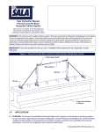
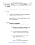
Important User Instructions
GENERAL:
Both ANSI Z359.1-1992 (R1999) 4.2.9 and ANSI 10.14
require users to be trained by a competent person other
Serial No.
Type:
than the user before this lanyard is used on the job.
Each unit shall be inspected every six months according
to the manufacturer’s recommendation and the date of
Inspected By:
Fall Protection
Lanyards
Instruction
Manual
OILFIELD, INDUSTRIAL & UTILITY SUPPLIES
Date:
each inspection shall be recorded on the attached tag.
Equipment showing any defect shall be withdrawn from
The fabric label attached to the lanyard indicates the
service immediately. All fall protection systems subjected
ANSI Z359.1-1992 (R1999) 4.2.9 and EN 355:2002
to impacts caused by a free fall or by testing shall be
numbers which the systems have also been proven to
removed from service and shall not be used again.
meet or exceed.
Do not alter this lanyard in any way. Failure to use
properly may result in serious bodily harm.
INSPECTION:
Single Positioning
Retractable Lanyard
Slow-Stop
Lanyard
Dual Positioning
Retractable Lanyard
Lanyard
Anchor
Locking
Snaps
Each unit shall be visually inspected for defects prior to
each use and particular attention should
be directed to the following potential
defects: (1) worn parts (2) loose or
damaged connection points or areas (3)
1 1/2”
Black Nylon
Webbing
(60” long)
STORAGE OF EQUIPMENT:
Each unit should be stored in a cool dry place and not
Frayed
Webbing
deterioration (4) operational defects (5)
subjected to direct sunlight.
CLEANING INSTRUCTIONS:
damaged or distorted snap hooks (6)
faulty springs (7) sharp edges (8) burrs
(9) cracks or (10) corrosion. Equipment
showing any defect shall be withdrawn
from service immediately.
In addition, all Lewis Slow-Stop
Lanyards must be inspected before each use for signs of
previous deployment: (1) ripped or missing 1” long red safety
stitching at the side of the yellow containment sleeve (2) torn
webbing (3) torn or broken containment sleeve or (4) overall
length of lanyard measures more than six inches longer than
length indicated on label.
All Lewis Manufacturing Company safety equipment is
1. Clean using warm water and a mild detergent.
Wipe with clean dry cloth.
2. Hang to air dry, away from direct source of heat.
Please keep this form along with the certification
on file for the life of the products you are using. It is
very important that these guidelines be followed in
order to avoid serious injury or even death. If you
have any questions regarding the use or inspection
of any Lewis Manufacturing Company equipment,
please feel free to call us collect at any time at (405)
634-5401.
inspected for quality assurance according to ANSI Z359.11992 (R1999) 4.2.9. A qualified person must inspect this
forget
Dtoon’tvisit
our
safety device twice a year using the listed potential defects
as a reference. The month and the year of inspection is
recorded by marking the correct letter or number on the tag.
The item in this box can be identified by referring to the
Now accepting
Visa and
MasterCard.
website on the
internet at:
1 /4”
White
Nylon
Tear-Away
Webbing
(inside
sleeve)
3
EC Typeexamination by:
SGS UK Ltd
Weston-super-Mare
BS22 6WA, UK
(Notified Body
No: 0120)
(Applies to SlowStop Lanyard only.)
Yellow
Nylon Fabric
Containment
Sleeve
Extension
Tail
Red Safety
Stitching
1” Yellow
Nylon
Webbing
(64” long)
Ladder
Snaps
Locking
Snaps
www.lewismanufacturingco.com
following information:
P.O. Box 95089 • 3601 S. Byers Oklahoma City, OK 73143 • (405) 634-5401
Toll Free: 1-888-398-4719 Fax: (405) 632-8608 • e-mail: [email protected]
P.O. Box 95089 • 3601 S. Byers Oklahoma City, OK 73143 • (405) 634-5401
Toll Free: 1-888-398-4719 Fax: (405) 632-8608 • e-mail: [email protected]
Lewis Fall Protection Lanyards
Revised 3/06
How To Use Lewis Fall Protection Lanyards
OILFIELD, INDUSTRIAL & UTILITY SUPPLIES
The purpose of the Lewis Slow-Stop Lanyard is to provide
the user a means of fall deceleration. The Slow-Stop Lanyard
shall not be used as a work positioning device. If work positioning
is required, the Lewis Tail Rope must be used in conjunction with
a Slow-Stop Lanyard. (See Photo)
Prior to each use, inspect
Slow-Stop
the stitches which seal the
Lanyard
Slow-Stop mechanism. (See
Photo) If any of these stitches are
torn or missing, immediately
remove the Slow-Stop from service
and replace with a new unit prior to
performing any work. Prior to each use,
the user must inspect all stitching and webbing of the Slow-Stop in question. Any
fraying, missing or torn stitches tears or
abrasions of the webbing or exposure of
the wear indicator shall indicate a need for
immediate replacement. Do not expose any
Lewis Slow-Stop lanyard to any heat
source, as this can damage the webbing and
create a fall hazard.The lanyard must be used
with a genuine Lewis Safety Belt for maximum safety.
The purpose of the Lewis Single and Dual Positioning
Retractable Lanyards is to provide the user a means of WORK
POSITIONING. Lewis Positioning Lanyards either in the single or
dual configuration SHALL NOT BE USED AS A DECELERATION
DEVICE. The user is required to utilize a deceleration lanyard
(Slow-Stop) or other type of fall deceleration device in addition to
our Positioning Lanyard or Steel Tail Rope. (See Photo)
Prior to each use, the user must inspect all stitching and webbing of the Lanyard in question. Any fraying, missing or torn
stitches, tears or abrasions of the webbing, or exposure of the
wear indicator, shall indicate a need for immediate replacement.
Do not expose any Lewis Lanyard to any heat source as this
could damage the webbing and create a fall hazard.
Always use the shortest lanyard possible. Lanyards must be
attached so maximum free fall is 1.8 feet (0.5 meters).
All Lewis lanyards are manufactured in conformance with the
provisions of ANSI Z359.1-1992 (R1999) 4.2.9 and they meet or
exceed the requirements outlined by ANSI 10.14 (1991).
This operating instructions manual must always be kept available
as long as the lanyard with which it was furnished is in service.
The inspection tag on the lanyard shall be kept current as per
instructions on the reverse side of this manual.
Step
#1
Slow-Stop
Lanyard
Single Positioning
Retractable
Lanyard
Dual Positioning
Retractable
Lanyard
Lanyard
Anchor
Open up
lanyard as
shown here.
Lanyard
Anchor
Size
Chart
Slow-Stop
Part No.
Length
SLO-2-Y
SLO-4-Y
SLO-6-Y
2’
4’
6’
Dual Positioning
Retractable Lanyard
Part No.
DPRL-2-Y
DPRL-4-Y
DPRL-6-Y
SPRL-2-Y
SPRL-4-Y
SPRL-6-Y
WARNING
P. O . B o x 9 5 0 8 9
•
3601 S. Byers
Part No.
LA-2-Y
LA-3-Y
LA-4-Y
LA-6-Y
Lanyard
in use.
“A” marking
on fall arrest
harness
denotes the
point for
attachment of
lanyard.
A
Extension
Tail
Length
2’
4’
6’
Fall protection lanyards must
ALWAYS be used in conjunction
with an approved anchorage connector. NEVER wrap a lanyard
around an anchorage for use without an approved anchorage connector such as: 1. Lanyard Anchor
2. Web Loop 3. Tie-back Lanyard
4. Wire Form Pipe Hook 5. Rope
Grab (Connecting Subsystem).
Single Positioning
Retractable Lanyard
Part No.
Attach genuine
Lewis Fall
Protection
Lanyard to the Dring on the back
between the
shoulders
(dorsal D-ring)
on a full body
harness.
Connect so the energy
absorber unit of the lanyard
is nearest to the body.
Length
2’
4’
6’
Lanyard Anchor
Do not alter any
Lewis Manufacturing equipment in any way. Alteration or improper use of this
lanyard can result in severe bodily harm or even death. Lewis
Manufacturing does not assume any liability for accidents or
injuries resulting from a field-repaired or altered belt. Avoid
attaching lanyard around sharp edges.
Each unit shall be visually inspected for defects prior to each
use as per directions described in the inspection section of this
pamphlet. Record inspection dates monthly.
Step
#2
Length
2’
3’
4’
6’
Extension Tail
Part No.
Length
ET-1.5-Y
1 /2’
1
WA R N I N G
Don’t use this lanyard if your weight
exceeds 300 lbs.! (136 kg.)
O k l a h o m a C i t y, O K 7 3 1 4 3
•
(405) 634-5401
Slow-Stop
Lanyard
Steel Tail
Rope
Always connect the energy absorber end of the lanyard
to the body support (harness). Connect the lanyard end
to the anchorage or anchorage connector. Component
style energy absorbers should be connected to the body
support first, then coupled to the rest of the system.
Some anchorage connector devices may be supplied
with permanently attached energy absorber. Use of an
additional energy absorber or energy absorbing lanyard
with these types of subsystems is not recommended.
To l l F r e e : 1 - 8 8 8 - 3 9 8 - 4 7 1 9
Fax: (405) 632-8608
Rear view
with
lanyard and
tail rope
secured for
fall arrest.
WARNING
Don’t use these products if your
weight exceeds 300 lbs.! (136 kg.)
•
e-mail: [email protected]
Important User Instructions
1.0 APPLICATIONS
A. To a D-ring to which another connector is attached.
1.1 PURPOSE: Lewis Manufacturing Company Energy Absorbing
Lanyards and Energy Absorbers are intended to be used as part of a
personal fall arrest system. Applications for these products include
inspection work, construction and demolition, maintenance, oil production, confined space rescue, and other similar activities where there
exists the possibility of an accidental fall. This equipment is specially
designed to dissipate fall energy and limit fall arrest forces transferred to
the body.
B. In a manner that would result in a load on the gate.
1.2 The following application limitations must be considered before
using this product:
A. CAPACITY: This equipment is for use by persons with a combined
weight (person, clothing, tools, etc.) of no more than 300 lbs.
Note: Large throat opening snap hooks should not be connected to standard size
D-rings or similar objects which will result in a load on the gate if the hook or Dring twists or rotates. Large throat snap hooks are designed for use on fixed structural elements such as rebar or cross members that are not shaped in a way that
can capture the gate of the hook.
C. In a false engagement, where features that protrude from the snap
hook or carabiner catch on the anchor and without visual confirmation
seems to be fully engaged to the anchor point.
D. To each other
E. Directly to webbing or rope lanyard or tie-back (unless the manufacturer’s instructions for both the lanyard and connector specifically
allows such a connection.
B. PHYSICAL AND ENVIRONMENTAL HAZARDS: Use of this
equipment in areas containing physical or environmental hazards may
require that additional precautions be taken to reduce the possibility of
damage to this equipment or injury to the user. Hazards may include,
but are not limited to: high heat, strong or caustic chemicals, corrosive
environments, the possibility of electric current flowing through this
equipment when working near high voltage power lines, explosive or
toxic gases, moving machinery, or sharp edges. Contact Lewis
Manufacturing if you have any questions about the application of this
equipment in areas where physical or environmental hazards are
present.
F. To any object which is shaped or dimensioned such that the snap
hook or carabiners with not close and lock, or that roll-out could occur.
C. TRAINING: This equipment is intended to be installed and used by
persons who have been properly trained in its correct application and
use.
1.3 Refer to national consensus (including ANSI Z359.1 and ANSI
A10.14), applicable local, state, and federal (OSHA) requirements governing this equipment for more information on Energy Absorbing
Lanyards, Energy Absorbers and associated system components.
2.0 SYSTEM REQUIREMENTS
2.3 ANCHORAGE STRENGTH: Anchorages selected for personal fall
arrest systems (PFAS) shall have a strength capable of sustaining static
loads, applied in the directions permitted by the PFAS, or at least: (A)
3,600 lbs. when certification exists (reference ANSI Z359.1 for certification definition), or (B) 5,000 lbs. in the absence of certification. When
more than one PFAS is attached to an anchorage, the anchorage
strengths set forth in (A) and (B) above must be multiplied by the number of PFAS attached to the anchorage. Per OSHA 1926.500 and
1910.66 - Anchorages used for attachment of PFAS shall be independent of any anchorage being used to support or suspend platforms, and
capable of supporting at least 5,000 lbs. per user attached, or be
designed, installed, and used as part of a complete PFAS which maintains a safety factor of at least two, and is supervised by a qualified person.
3.0 OPERATION AND USE
2.1 COMPATIBILITY OF CONNECTORS: Lewis Manufacturing equipment is designed for use with Lewis Manufacturing approved components and subsystems only. Substitutions or replacements made with
non-approved components or systems may jeopardize compatibility of
equipment and may effect the safety and reliability of the complete system.
COMPATIBILITY: Connectors are considered to be compatible with
connecting elements when they have been designed to work together in
such a way that their sizes and shapes do not cause their gate mechanisms to inadvertently open regardless of how they become oriented.
Contact Lewis Manufacturing if you have any questions about compatibility.
D. FALL CLEARANCE: Should a fall occur, there must be sufficient
clearance in the fall area to arrest the fall before striking the ground or
other object. energy absorbers can extend the fall arrest distance by up
to 42 inches. Figure 4 shows how to estimate fall clearance distance
when using an energy absorbing lanyard or energy absorber subsystem. Other factors may influence the required clearance distances. For
example, using an energy absorbing lanyard or energy absorber with a
rope grab (fall arrestor) may require additional clearance due to stretch
in the lifeline or sliding of the rope grab on the lifeline during fall arrest.
Some full body harness models incorporate a sliding (positional) D-ring
in the back as the fall arrest attachment, movement of this D-ring during
fall arrest can increase the fall clearance distance required. Use caution
when assembling system components that could act to extend the fall
arrest distance (and therefore fall clearance
required). Refer to manufacturer’s instructions
for each part of the system for more information on fall clearance.
E. SWING FALLS: Swing falls occur when
the anchorage point is not directly above the
point where a fall occurs. The force of striking
an object while swinging (horizontal speed of
the user due to the pendulum affect) can be
great and may cause serious injury. In a swing
fall situation, the total vertical fall distance of
the user will be greater than if the user had
fallen vertically directly below the total free fall
distance and the area needed to safely arrest
the fall. Swing falls can be minimized by workSwing Falls ing as directly below the anchorage point as
possible. Never permit a swing fall if injury
could occur. If a swing fall situation exists in your application, contact
Lewis Manufacturing before proceeding.
WARNING: Consult your doctor if there is reason to doubt your fitness
to safely absorb the shock from a fall arrest. Age and fitness seriously
affect a worker’s ability to withstand falls. Pregnant women or minors
must not use Lewis Manufacturing energy absorbing lanyards.
G. RESCUE: Should a fall occur, the user
(employer) must have a rescue plan and the
ability to implement it.
2.2 Making Connections: Use only self-locking snap hooks and carabiners with this equipment. Use only connectors that are suitable for
each application. Ensure all connections are compatible in size, shape
and strength. Do not use equipment that is not compatible. Ensure all
connectors are fully closed and locked.
3.2 PLAN your fall protection system before starting your work. Take
into consideration factors that effect your safety before, during and after
a fall. The following list gives some important points to consider when
planning your system:
Lewis Manufacturing connectors (snap hooks and carabiners) are
designed to be used only as specified in each product’s user’s instructions. See Figure 3 for inappropriate connections. Lewis Manufacturing
snap hooks and carabiners should not be connected:
A. ANCHORAGE: Select a rigid anchorage point that is capable of
supporting the required loads. See section 2.3. The anchorage location
must be carefully selected to reduce possible free fall and swing fall
hazards and to avoid striking an object during a fall. The anchorage
should be generally level (horizontal) to prevent the anchorage connec-
3601 S. Byers
C. FALL ARREST FORCES: The assembled fall arrest system must
keep fall arrest forces below 1,800 lbs. when used with a full body harness.
F. SHARP EDGES: Avoid working where the lanyard, subsystem, or
other system components will be in contact with, or abrade against,
unprotected sharp edges. Do not loop lanyard around small diameter
structural members. If working with this
equipment near sharp edges is unavoidable,
protection against cutting must be provided
by using a heavy pad or other means over
the exposed sharp edge.
3.1 BEFORE EACH USE of this equipment, carefully inspect it to
assure that it is in good working condition. Check for worn or damaged
parts. Ensure all hardware is present and secure, and is not distorted or
have any sharp edges, burrs, cracks or corrosion. Ensure self-locking
snap hooks or carabiners work properly. Inspect rope or webbing for
wear, cuts, burns, frayed edges, breaks or other damage. See section
5.0 for further inspection details. Do not use if inspection reveals an
unsafe condition.
•
B. FREE FALL: Personal fall arrest systems must be rigged such that
the potential free fall is never greater than 6 feet (5 feet per ANSI
A10.14). Avoid working above your anchorage level to avoid an
increased free fall distance.
WARNING: Do not alter or intentionally misuse this equipment. Consult
Lewis Manufacturing when using this equipment in combination components or subsystems other than those described in this manual. Some
subsystem and component combinations may interfere with the operation of this equipment. Use caution when using this equipment around
moving machinery, electrical hazards, chemical hazards, and sharp
edges.
Connectors (hooks, carabiners and D-rings) must be capable of supporting at least 5,000 lbs. (22kN). Connectors must be compatible with
anchorage or other system components. Do not use equipment that is
not compatible. Non-compatible connectors may unintentionally disengage. Connectors must be compatible in size, shape and length. Self
locking snap hooks and carabiners are required by ANSI Z359.1 and
OSHA.
P. O . B o x 9 5 0 8 9
tor from sliding down an incline when in use, which could cause serious
injury to the user.
O k l a h o m a C i t y, O K 7 3 1 4 3
•
(405) 634-5401
H. AFTER A FALL: Lanyards with integral
energy absorbers, or energy absorber components which have been subjected to the
forces of arresting a fall must be removed
from service and destroyed.
3.3. MAKING CONNECTIONS: When using
a hook to connect to an anchorage, or when
coupling components of the system together,
ensure accidental disengagement (roll-out)
To l l F r e e : 1 - 8 8 8 - 3 9 8 - 4 7 1 9
A. CONNECTING TO ANCHORAGE OR ANCHORAGE CONNECTOR: Always connect the energy absorber end of the lanyard to the
body support (harness). connect the lanyard end to the anchorage or
anchorage connector. Component style energy absorbers should be
connected to the body support first, then coupled to the rest of the system. Some anchorage connector devices may be supplied with permanently attached
energy absorber.
Use of an addiAnchorage
Anchorage
tional energy
Connector
Connector
Anchorage
Connector
absorber or energy absorbing lanyard with these
Energy
Energy
Connecting
Absorbing
Absorbing
types of subsysSubsystem
Energy
Lanyard
Lanyard
(Rope
Grab)
Absorbing
tems is not recomLanyard
mended. 100%
tie-off “Y” type
energy absorbing
lanyards can be
used to provide
continuous fall
protection while
Connecting to Anchorage
ascending,
descending, or
moving laterally. With one lanyard leg attached, the worker can move to
a new location, attach unused lanyard leg, and disconnect attached leg.
This procedure is repeated until new location is reached. With the SlowStop 100% tie-off type lanyard, only one leg of the lanyard shall be
attached to the anchorage connector once working location is reached.
Attaching a Tie-Back Lanyard: Place the tie-back lanyard over the
anchoring structure. Ensure the lanyard is not twisted. Adjust the floating D-ring so it hands below the anchoring structure. Attach the lanyard
end hook to the floating D-ring.
Attaching a Lanyard with Wire Form Pipe Hook: The wire form
Pull Back
Gate With
Thumb
Push
Inward
Push
Up
Rotate
Clockwise
STEP THREE
STEP TWO
STEP ONE
WARNING: Read and follow manufacturer’s
instructions for associated equipment (full
body harness, rope grab, etc.) used in your
fall protection system.
IMPORTANT: For special (custom) versions
of this product, follow the instructions herein.
If included, see supplement for additional
instructions.
cannot occur. Roll-out occurs when interference between a hook and
the mating connector causes the hook’s gate or keeper to accidentally
open and release. Roll-out may occur when a hook is connected to an
undersized ring such as an eye bolt or other non-compatible shaped
connector. Self locking snap hooks or self-locking and self-closing gate
carabiners should be used to reduce the possibility of roll-out when
making connections. Do not use hooks or connectors that will not completely close over the attachment object. For these situations, use a tieoff adaptor or other anchorage connector to allow a compatible connection. Do not knot lanyard in any manner, and do not hook lanyard back
into itself (choker style). Snap hooks and carabiners must not be connected to each other. Do not attach snap hooks to web loops.
STEP ONE
Depress
Locking
Mechanism
With Index
Finger
STEP TWO
Push
Inward
Rotate
Clockwise
STEP ONE
STEP ONE
STEP TWO
Depress
Locking
Mechanism
With Palm
of Hand
Push Inward
STEP TWO
Making Connection
Fax: (405) 632-8608
•
e-mail: [email protected]
Proper Connection
Load
Direction
IMPROPER
CONNECTION
IMPROPER
CONNECTION
Load Direction
Attaching Wire Form
pipe hook is intended
for use with pipes up to
three inches in diameter. The anchorage
must be geometrically
compatible in size and
shape. Do not side load
the pipe hook. do not
allow the pipe hook to
contact electrical
sources. Squeeze the
handle to open the
hook. Place hook
around the anchorage
and release handle.
When connecting to an
anchorage, ensure the
hook fully closes and
closure hooks engage
eye loops on hook
body.
B. CONNECTING TO THE BODY SUPPORT: Connect the energy
absorbing lanyard or energy absorber to the D-ring on the back
between the shoulders (dorsal D-ring) on a full body harness. Connect
Insert lanyard web loop through
web loop or D-ring on harness.
possible interference with the operation of the rope grab by the energy
absorber “pack”. Attaching a component style energy absorber to a rope
grab is not recommended, with the exception of a “direct-coupling”
between a rope grab and a harness. Some rope grabs may be supplied
with a permanently attached energy absorbing lanyard. For these
cases, use of an additional energy absorber connected between the
rope grab and the body support is not recommended. In some cases, it
may be permissible to couple an energy absorber component between
the anchorage (or anchorage connector) and the rope grab lifeline. In all
cases, ensure the length of the energy absorber or energy absorbing
lanyard does not exceed the rope grab manufacturer’s recommended
maximum connection length (3 feet maximum per ANSI Z359.1).
D. CONNECTING TO SELF RETRACTING LIFELINE:
Lewis Manufacturing does not recommend connecting an energy
absorbing lanyard or energy absorber component to a self retracting
lifeline. Special applications do exist where it may be permissible.
Contact Lewis Manufacturing if considering connecting an energy
absorbing lanyard to a self retracting lifeline.
Please keep this form along with the
certification on file for the life of the products you are using. It is very important that
these guidelines be followed in order to
avoid serious injury or even death. If you
have any questions, concerns or doubts
regarding safety equipment inspection or
placing this or other Lewis Manufacturing
product(s) into service, we urge you to contact us collect at any time at (405) 634-5401
or toll-free at 1-888-398-4719.
Step 3. ENERGY ABSORBING COMPONENT: Inspect energy absorber to
determine if it has been activated. there should be no evidence of elongation.
Ensure energy absorber cover is secure and not torn or damaged. On the SlowStop Lanyard models, the lanyard webbing will tear out to reveal the warning on
the impact indicator label.
Step 4. All labels should be present and fully legible.
3.4 After use, return the lanyard for cleaning or storage as described in
section 6.0
Step 5. Inspect each system component or subsystem per associated manufacturer’s instruction.
Step 6. Record the inspection date and results in the inspection log.
4.0 TRAINING
5.3 If inspection reveals an unsafe condition, remove unit from service immediately and destroy, or contact an authorized service center for repair.
4.1 It is the responsibility of all users of this equipment to understand
these instruction, and to be trained in the correct installation, use and
maintenance of this equipment. these individuals must be aware of the
consequences of improper installation or use of this equipment. This
user manual is not a substitute for a comprehensive training program.
Training must be provided on a periodic basis to ensure proficiency of
the users.
Harness Web Loop
or D-ring
Web Loop on Energy
Absorbing Lanyard
protective gloves when inspecting wire rope. Inspect for broken wires by passing
cable through gloved hands, flexing it every few inches to expose breaks. Broken
wires can be removed by bending the wire back and forth parallel to the rope
length. Do not attempt to pull wires out of rope. Remove the energy absorbing
lanyard from service immediately and destroy if there are six or more randomly
distributed broken wires in one lay, or three or more broken wires in one strand in
one lay. A “lay” of wire rope is the length of wire rope that it takes for a strand (the
larger groups of wires) to complete one revolution or twist along the rope.
Remove the energy absorbing lanyard from service immediately and destroy if
there are any broken wires within one inch of the metal compression sleeves
(swages) at either end of the assembly. The wire rope should be free of corrosion.
WARNING
All Lewis SlowStop lanyards
are manufactured with a one inch long
section of red safety stitching at the base of the
yellow containment sleeve. When this red stitching is torn or missing, the Slow-Stop unit has
been deployed and MUST be removed from service and replaced immediately.
NOTE: Only Lewis Manufacturing or parties authorized in writing may make
repairs to this equipment.
The following inspection items are indications that
the energy absorber has been subjected to impact
loading and has been activated.
Torn Webbing
IMPORTANT: Training must be conducted without exposing the trainee
to a fall hazard. Training should be repeated on a periodic basis.
Insert opposite end of lanyard through
harness web loop or D-ring.
5.0 INSPECTION
Torn or broken cover
5.1 FREQUENCY
• Before each use, visually inspect per steps listed in sections 5.2
and 5.3.
• The lanyard must be inspected by a competent person other than
the user at least annually. See sections 5.2 and 5.3 for guidelines.
Record the results of each formal inspection in the inspection log found
in section 9.0
Pull the lanyard through the
connecting web loop to secure.
Attaching Web Loop
so the energy absorber portion of the lanyard is on the body support
side. Lewis Manufacturing does not recommend using a body belt for
fall arrest applications. If using a body belt, connect the energy absorbing lanyard or energy absorber to the D-ring and position the belt so the
D-ring is located on the back side of the body.
IMPORTANT: If the energy absorbing lanyard or energy absorber component has been subjected to fall arrest or impact forces, it must be
immediately removed from service and destroyed.
IMPORTANT: Extreme working conditions (harsh environment, prolonged use, etc.) may require increasing the frequency of inspections.
Open end or ripped
out stitching
Measured length is more
than six inches longer than
length marked on label.
Inspecting the Energy Absorber for Activation
5.2 INSPECTION STEPS
Attaching a Lanyard with Web Loops:
1. Insert the energy absorbing lanyard web loop through the harness web loop or D-ring.
2. Insert the opposite
end of the energy
Do Not Allow Gate
absorbing lanyard
To Contact
through the connecting
Anchorage Member
web loop.
3. Pull the attached
energy absorbing lanyard through the connecting web loop to
secure.
PROPER CONNECTION
IMPROPER
CONNECTION
Attaching Tie-Back
P. O . B o x 9 5 0 8 9
•
C. CONNECTING TO
A ROPE GRAB (FALL
ARRESTOR): It is recommended the lanyard
end (vs. the energy
absorber end) be
attached to the rope
grab. This recommendation is made to reduce
3601 S. Byers
Step 1. Inspect energy absorbing lanyard or energy absorber component hardware (snap hooks, adjusters, swages, thimbles, etc.). These
items must not be damaged, broken, distorted, or have any sharp
edges, burrs cracks, worn parts, or corrosion. Ensure the connecting
hooks work properly. Hook gates must move freely and lock upon closing. Ensure adjusters (if present) work properly.
Step 2. Inspect the energy absorbing lanyard or energy absorber
component per the following as applicable:
WEBBING AND STITCHING: The webbing material must be free of
frayed, cut, or broken fibers. Check for tears, abrasions, mold, burns, or
discoloration, etc. The webbing must be free of knots, excessive discolored, or brittle areas. check for ultraviolet damage indicated by discoloration and the presence of splinters or slivers on the webbing surface.
All of the above factors are known to reduce webbing strength.
Damaged or questionable webbing should be replaced. Inspect stitching
for pulled or cut stitches. Broken stitches may be an indication the energy absorbing lanyard or energy absorber component has been impact
loaded and must be removed from service.
6.0 MAINTENANCE, SERVICING, STORAGE
7.0 SPECIFICATIONS
6.1 Clean lanyard with water and a mild detergent solution. Wipe off hardware
with a clean, dry cloth, and hang to air dry. do not force dry with heat. If you
have any questions regarding cleaning of this equipment, or require more information, contact Lewis Manufacturing. An excessive buildup of dirt, paint, etc.,
may prevent the lanyard from working properly, and in severe cases, degrade
the webbing or rope to a point where it has become weakened and should be
removed from service. If you have any questions concerning the condition of
your lanyard, or have any doubt about putting it into service, contact Lewis
Manufacturing.
- The maximum arresting force of Lewis
Manufacturing lanyards and components when
dynamically tested accordance with ANSI
Z359.1 is 900 lbs.
- The maximum elongation of the Energy
Absorbing lanyard or Energy Absorber component when dynamically tested in accordance
with ANSI Z359.1 is 42 inches.
- Maximum free fall distance must be no
greater than 6 feet per federal law and ANSI
Z359.1 (5 feet per ANSI A10.14)
6.2 Additional maintenance and servicing procedures (replacement parts) must
be completed by a factory authorized service center. Authorization must be in
writing. Do not disassemble the unit. See section 5.1 for inspection frequency.
6.3 Store the lanyard in a cool, dry, clean environment out of direct sunlight.
Avoid areas where chemical vapors may exist. Thoroughly inspect the lanyard
or energy absorber component after extended storage.
WIRE ROPE: Inspect entire length of the wire rope. Always wear
O k l a h o m a C i t y, O K 7 3 1 4 3
•
(405) 634-5401
To l l F r e e : 1 - 8 8 8 - 3 9 8 - 4 7 1 9
Fax: (405) 632-8608
•
e-mail: [email protected]