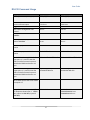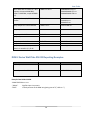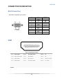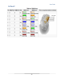
1
USERS GUIDE DXM G2 Series Digital Xtreme Card Cages 8x8, 16x16, 32x32 i Manual Number: 131227 Firmware v2.2.6 & above SAFETY INSTRUCTIONS Please review the following safety precautions. If this is the first time using this model, then read this manual before installing or using the product. If the product is not functioning properly, please contact your local dealer or Aurora for further instructions. The lightning symbol in the triangle is used to alert you to the presence of dangerous voltage inside the product that may be sufficient to constitute a risk of electric shock to anyone opening the case. It is also used to indicate improper installation or handling of the product that could damage the electrical system in the product or in other equipment attached to the product. The exclamation point in the triangle is used to alert you to important operating and maintenance instructions. Failure to follow these instructions could result in injury to you or damage to the product. Be careful with electricity: Power outlet: To prevent electric shock, be sure the electrical plug used on the product power cord matches the electrical outlet used to supply power to the Aurora product. Use only the power adapter and power connection cables designed for this unit. Power cord: Be sure the power cord is routed so that it will not be stepped on or pinched by heavy items. Lightning: For protection from lightning or when the product is left unattended for a long period, disconnect it from the power source. . Also follow these precautions: Ventilation: Do not block the ventilation slots if applicable on the product or place any heavy object on top of it. Blocking the air flow could cause damage. Arrange components so that air can flow freely. Ensure that there is adequate ventilation if the product is placed in a stand or cabinet. Put the product in a properly ventilated area, away from direct sunlight or any source of heat. Overheating: Avoid stacking the Aurora product on top of a hot component such as a power amplifier. Risk of Fire: Do not place unit on top of any easily combustible material, such as carpet or fabric. Proper Connections: Be sure all cables and equipment are connected to the unit as described in this manual. Object Entry: To avoid electric shock, never stick anything in the slots on the case or remove the cover. Water Exposure: To reduce the risk of fire or electric shock, do not expose to rain or moisture. Cleaning: Do not use liquid or aerosol cleaners to clean this unit. Always unplug the power to the device before cleaning. ESD: Handle this unit with proper ESD care. Failure to do so can result in failure. FCC This device complies with Part 15 of the FCC Rules. Operation is subject to the following two conditions: (1) This device may not cause harmful interference. (2) This device must accept any interference received, including interference that may cause undesired operation. Trademarks All trademarks in this document are the properties of their respective owners. i User Guide TABLE OF CONTENTS PACKAGE CONTENTS .............................................................................................................1 INTRODUCTION ........................................................................................................................2 About ..................................................................................................................................................... 2 Features ................................................................................................................................................ 2 MATRIX FRAMES, CARDS, & ACCESSORIES ........................................................................3 DESCRIPTION...........................................................................................................................9 Front Panel DXM G2 Series ................................................................................................................. 9 Rear Panel DXM G2 Series ................................................................................................................ 10 OPERATION ............................................................................................................................ 11 Front Panel Menu Structure .................................................................................................................11 LCD Display Readout & Front Backlit Keypad ................................................................................... 14 Switching with Front Panel ................................................................................................................. 19 EDID Management ............................................................................................................................. 21 CARD FUNCTIONALITY .........................................................................................................22 HDBaseT Cards .................................................................................................................................. 22 HDMI Cards ........................................................................................................................................ 23 SERIAL COMMANDS ..............................................................................................................24 RS-232 Commands ............................................................................................................................ 24 RS-232 Command Usage ................................................................................................................... 27 DXW-2 Series Wall Plate RS-232 Reporting Examples ..................................................................... 28 CONNECTOR PIN DEFINITION ..............................................................................................29 RS-232 Serial Port .............................................................................................................................. 29 HDMI ................................................................................................................................................... 29 CAT5e/6/7 ........................................................................................................................................... 30 APPENDIX 1 Troubleshooting ...........................................................................................31 APPENDIX 2 Firmware Update ..........................................................................................32 DXM Update Utility & Hardware ......................................................................................................... 32 APPENDIX 3 Technical Specifications..............................................................................33 APPENDIX 4 Cabling .........................................................................................................34 APPENDIX 5 Warranty .......................................................................................................35 ii PACKAGE CONTENTS Please make sure the following items are included within your package. Contact your dealer if any items are missing or damaged. DXM Card Cage (DXM-88, DXM-1616, DXM-3232 Accordingly) IEC Power Cord x 1 Front Door Triangle Access Key Firmware updating cables (RJ-11 to inline) Front Door Triangle Access Key Matrix Frame User Manual Power cable RS-232 Communication Cable Optional Accessories Refer to Matrix Frames, Cards, Accessories section for full list of products available for the DXM G2 Series. Note: Go to www.auroramultimedia.com for latest manual and firmware 1 User Guide INTRODUCTION About Aurora's 2nd generation Digital Xtreme Matrix (DXM) switchers now with HDBaseT CAT I/O cards offering 1080P 60Hz transmission over CAT cable up to 600ft. All units with auto EDID learning and management for ease of setup. Associated HDBaseT Tx and Rx modules are remotely powered by the DXM units over CAT cable. The new units also offer flexible RS232 signal routing to individual outputs or to all outputs simultaneously for unprecedented display control. With a full assortment of Input cards no format is left behind with crystal clear digital conversion to 1920 x 1080 60Hz. Features Card Cage Sizes of 8x8, 16x16, 32x32 Configurable as 4-channels per Card 12.8Mbps Bandwidth per Port Hot Pluggable Input and Output Cards Redundant* Power Supply for 16x16 and 32x32 EDID Management HDCP Compliant VGA Input / Output Cards 3G/HD/SD SDI Input / Output Cards HDMI Input / Output Cards (Output Cards w/Audio De-embedding & Auto DVI Detect) HDBaseT CAT Input / Output Cards (Powers remote Tx/Rx units & bi-directional RS232) Fiber Input / Output Cards up to 6600 feet (2000m) YPbPr Input Cards Composite Input Cards Presets Front LCD status & Front Panel Button Control RS-232 Control Ethernet Control * Note: Depending on what type of cards and external devices are being powered will determine if the second power supply is used for additional power handling or redundant operation. 2 User Guide MATRIX FRAMES, CARDS, & ACCESSORIES DIGITAL XTREME (GEN 2) – FRAMES & CARDS Matrix Card Frames DXM-88-G2 8x8 Digital Xtreme Matrix Card Cage DXM-1616-G2 16x16 Digital Xtreme Matrix Card Cage DXM-3232-G2 32x32 Digital Xtreme Matrix Card Cage Input Cards DXCI-4-HDMI-G2 4 Input HDMI Card DXCI-4-LHDMI-G2 4 Input HDMI Card with Loop Out for Cascading DXCI-4-HDBT1-G2 4 Input HDMI HDBaseT 230' CAT Card 3 User Guide DXCI-4-HDBT2-G2 4 Input HDMI HDBaseT 328'/600' CAT Card DXCI-4-HDBT2E-G2 4 Input HDMI HDBaseT 328'/600' CAT Card with Ethernet and internal / external POE DXCI-4-DVI-G2 4 Input DVI HDCP & Auto Eq for 30m Cable Support Card DXCI-4-FIBR3-G2 4 Input Dual Multi-mode (300m) / Single-mode (2km) Fiber Card DXCI-4-VGA-G2 4 Input VGA with Audio Card with 4 VGA breakout adaptors DXCI-4-YPbPr-G2 4 Input YPbPr with Audio Card with 4 YPbPr / audio RCA female breakout adaptor DXCI-4-2S2H-G2 4 Input 2 3G SDI & 2 HDMI Card 4 User Guide DXCI-4-2V2H-G2 4 Input 2 VGA with Audio & 2 HDMI Card with 2 VGA / audio breakout adaptors DXCI-4-SDI-G2 4 Input 3G/HD/SD/SDI Card Output Cards DXCO-4-HDMI-G2 4 Output HDMI with audio de-embedder Card DXCO-4-HDBT1-G2 4 Output HDMI HDBaseT 230' CAT Card DXCO-4-HDBT2-G2 4 Output HDMI HDBaseT 328'/600' CAT Card DXCO-4-DVI-G2 4 Output DVI / HDCP Card DXCO-4-SDVI-G2 4 Output Seamless Switcher DVI (No HDCP) Card DXCO-4-FIBR3-G2 4 Output Dual Multi-mode (300m) / Single-mode (2km) Fiber Card 5 User Guide DXCO-4-VGA-G2 4 Output VGA Card with 2 VGA / audio breakout adaptors DXCO-4-2S2H-G2 4 Output 2 3G SDI & 2 HDMI Card DXCO-4-2V2H-G2 4 Output 2 VGA with Audio & 2 HDMI Card with 2 VGA / audio breakout adaptors DXCO-4-SDI-G2 4 Output 3G/HD/SD/SDI Card Accessories DXC-BLANK-G2 Blank Panel for Slot DXM-PWR-G2 DXM Power Supply for 16x16 and 32x32 6 User Guide DIGITAL XTREME ACCESSORIES External HDBT / Fiber Boxes and Wall Plates DXE-CAT-RX1 230' HDBaseT Receiver (No PS) DXE-CAT-RX2 328'/600' HDBaseT Receiver (No PS) DXE-CAT-TX1 230' HDBaseT Transmitter (No PS) DXE-CAT-TX2 328'/600' HDBaseT Transmitter (No PS) DXW-2 2 Input HDBaseT Wall Plate (VGA & HDMI) - 230' CAT Extender DXW-2E 2 Input HDBaseT Wall Plate (VGA & HDMI) - 230' CAT Extender with LAN DXW-2EU 2 Input HDBaseT Wall Plate (VGA & HDMI) - 230' CAT Extender with LAN and Dual USB 7 User Guide DXE-FIBR-TX3 DXE-FIBR-RX3 HDMI to Dual Multi-mode (300m) / Single-mode (2km) Fiber Transmitter Dual Multi-mode (300m) / Single-mode (2km) Fiber Receiver to HDMI Rack Mounts / Power Supplies / Cables DXE-CAT-RK3 3RU Rack Mount Kit for DXE-CAT-S1/S2/S2L (Fits up to 16 DXE-CAT units in 3RU space) DXE-CAT-RK3BL Blank Panels for DXE-CAT-RK3 Rack Mount PS0053-1 24VDC PS w/US Adaptor (DXE-CAT) CA0052-F2T3R 3.5mm TRS to FEMALE DB9 2-TX 3-RX (Null Modem) CA0052-F3T2R 3.5mm TRS to FEMALE DB9 3-TX 2-RX CA0052-M2T3R 3.5mm TRS to MALE DB9 2-TX 3-RX (Null Modem) CA0052-M3T2R 3.5mm TRS to MALE DB9 3-TX 2-RX 8 User Guide DESCRIPTION Front Panel DXM G2 Series LCD Backlit display for the status and operation 0-9 Input / Output port selection number keys. Switch The HDMI signal toggle selection key. Example: 3→ Switch→6→END→ENTER to switch signal from the input 3 to output 6. Example: CANCEL→1→&→3→END→ENTER to clear signal from the output 1 & 3. Space key which is used to switch to many output ports at once. & All Example: 1→Switch→2→&→3→&→6→END→ENTER to switch signal from the input 1 to outputs 2, 3, 6 at the same time. All command sends an input to every output at once or all inputs to each output on a one to one. Example: 7→ALL means switching signal from input 7 to the all output ports. Example: CANCEL→ALL means turn off all output ports. The save key saves the I/O configuration into a memory preset Save Example: SAVE→2 saves all I/O status into the NO.2 memory cell. “0~9” ten presets in all. Recall The recall key will restore a saved memory preset. Example: RECALL→2 restore the I/O status from the NO.2 memory preset. Status The status shows the matchup of inputs to outputs. Cancel END ENTER The cancel key returns the DXM back to standby mode Example: 1→Switch→2→END→CANCEL clears the input order and user can type the new one if required. The end key finishes a selection order. The enter key confirms a process selection. 9 User Guide Rear Panel DXM G2 Series DXM-88-G2 DXM-3232-G2 DXM-1616-G2 IEC Power Connector(s) 110 / 220 power connector. DXM-1616 / DXM-3232 have 2 for redundant power. The lower power connector is the primary when a single supply is installed. Note: Depending on what type of cards and external devices are being powered will determine if the second power supply is used for additional power handling or redundant operation. Fan Card The card with the silver handle is for the fans. (DXM-1616 & DXM-3232) Input Cards The model will determine the amount of input cards. There are 4 ports per input card. The 8x8 has 2, 16x16 has 4, and the 32 x 32 has 8. Note the silk screen in the corner to match the cards in the correct slot type. Cards are hot swappable. Output Cards The model will determine the amount of output cards. There are 4 ports per output card. The 8x8 has 2, 16x16 has 4, and the 32 x 32 has 8. Note the silk screen in the corner to match the cards in the correct slot type. Cards are hot swappable. LAN Future Use. At this time if LAN operation is required it is recommend to use the Nugget Serial on the RS-232 port. RS-232 Main Control Port. Refer to the Serial Command section for available commands. Recommended baud rate is 115k 8N1 10 User Guide OPERATION Front Panel Menu Structure Version 2.26 & above Main Menu: 1. EDID Setting 2. RS232 Setting 3. Seamless Setting 4. Version 5. Language 6. Beep Setting 7. Keypad Light 8. LCD Backlight 9. System Reset 10. Back Sub Menu: EDID Setting 1. EDID Update 1/ External EDID 2/ Default EDID 3/ Back 2. EDID Manage 1/ Save EDID 2/ Delete EDID 3/ Back 3. EDID Info 4. Back 11 User Guide RS232 Setting 1. Main PCB 1/ Baud Rate 2/ Data bits 3/ Stop bit 4/ Parity 5/ Back 2. Input 1-16 3. Output 1-16 4. Back Seamless Set 1. ResolutionSet 1/ 1920 x 1080p 2/ 1280 x 720p 3/ 1440 x 900 4/ 1366 x 768 5/ 1024 x 768 2. DemoMode Set 3. Back Version Info 1. Main Board 2. Input Card 3. Output Card 4. InRs232 Card 5. OutRs232 Card 6. Back Language 1. English 2. Back Beep Setting 1. Turn on 2. Turn off 3. Back 12 User Guide Keypad Light 1. Turn on 2. Turn off 3. Back LCD Backlight 1. Always on 2. 20 minutes 3. 15 minutes 4. 10 minutes 5. 5 minutes 6. Back 13 User Guide LCD Display Readout & Front Backlit Keypad Navigation Menu – Pressing will cause the System Settings Menu to appear with 10 selections to choose from as listed below. Up / Down – Allows scrolling of the choices on the menu. Enter – Selects the highlighted choice. Cancel – Backs out one level of menu. Power Up Ready & Backed out of Menu 14 User Guide EDID Settings The EDID settings allow the managing of all EDID stored in the system. RS-232 Settings The RS-232 settings can be set for the various baud rates, data bits, and stop bits for all ports. 15 User Guide Seamless Settings Allows the selction of a few standard resolutions. This menu will only work for the seamless switching boards. Version Information Displays the units firmware for the main MCU, cards, and HDBaseT comunication ports. FM0 is the main board fimware. It is not unusual for a card to have a different firmware revision from the main board however when upgrading firmware it is always best to update all cards to latest firmware as sometimes there can be incompatibility based on the changes. Currently 2.2.6 and 2.2.5 will co-exist together. InRs232 & OutRs232 Card selection is the firmware for the communication port on HDBT cards. Language Settings Currently english is the only selection. 16 User Guide Beep Settings Allows the beep sound for each key press to be turned off and on. Keypad Light Settings Allows the keypad green backlight to be turned off and on. LCD Backlight Settings Allows the LCD backlight to be turned off and on or on a timer. Please note if you turn it off the room will need to be well lit to ready the information on the screen. System Reset This selection will restore all factory settings. After a firmware upgrade it is usually a good idea to do a system reset. 17 User Guide Back Out of Menu Returns back to Ready Screen 18 User Guide Switching with Front Panel Note: Please use the following sequence for proper results. 1) Connect the source(s) output to the input(s) of the appropriate card 2) Connect the output(s) of this appropriate card to the destination(s) (ex. Display) input 3) Connect power cable and switch unit on. The indicator light will then light as well as the front LCD. 4) Finally, turn on the resource and display devices. 5) Use front panel to select the I/O port. Press the number key for required input channel Press the “Switch” Press the number key for required output channel Press the “END” Press the “ENTER” at last Example: Input 2 to Output 5 - 2→ Switch→5→END→ENTER” 19 User Guide Examples of operation Example: To switch signal from the input 1 to Output 3 and 4 at the same time. 1. press the input “1” 2. press the “switch” 3. press the output”3” 4. press the “&” 5. press the output “4” 6. press the “end” 7. press the “enter” 20 User Guide EDID Management 1) - Copy EDID from an output to one or multiple inputs: Menu EDID Settings EDID Update External EDID. Command format: [Output#] Switch [Input#] End Enter Example: 2 Switch 1 End Enter: copy EDID from output 2 to input 1. 2 Switch 1&2&3 End Enter: copy EDID from output 2 to inputs 1, 2 and 3. 2) – Save EDID profile: Menu EDID Settings EDID Manage Save EDID Command format: [Output#] Switch [Profile#] End Enter Example: 2 Switch 1 End Enter: save EDID from output 2 to profile #1. 3) – Load/Use saved EDID profiles for one or multiple inputs: Menu EDID Settings EDID Update Default EDID Select an EDID profile. Command Format: [Input#] End Enter Example: Profile 2 is selected. 1&2 End Enter: EDID profile #2 is sent to input 1 and 2. 21 User Guide CARD FUNCTIONALITY HDBaseT Cards HDBaseT input and output cards are designed to receive or transmit audio, video, control, and power up to 600ft with 24bit 1080p 60Hz depending on model using a single common CAT 5e / 6 / 6A cable. DXCI-4-HDBT1 & DXCO-4-HDBT1 will go up to 230ft with 36bit color depth. DXCI-4-HDBT2 & DXCO-4-HDBT2 will go up to 328ft 48 bit color depth or 600ft with 24bit color depth (CAT 6A shielded cable required for this distance). The output card has the unique ability to auto detect a DVI display or device connected and automatically remove the audio from the signal even if the source is HDMI. This saves space and cost as an external device to strip the audio electrically is not required. The need to learn a DVI EDID is not required with the DXM series due to this feature. DXCI-4-HDBT1-G2 / DXCI-4-HDBT2-G2 DXCO-4-HDBT1-G2 / DXCO-4-HDBT2-G2 LED W D C V Description HDBT port microprocessor is working properly when flashing HDCP Status LED will be solid when HDCP is present or flash when there is none. Connectivity LED should be solid with a proper cable link to HDBaseT transmitter or receiver accordingly. Video Signal LED should be solid when video is present 22 User Guide HDMI Cards HDMI input and output cards support 1080p 60Hz video resolutions with stereo and Dolby® Surround Sound audio. The input and output cards will work with DVI signals. The output card has the unique ability to auto detect a DVI display or device connected and automatically remove the audio from the signal even if the source is HDMI. This saves space and cost as an external device to strip the audio electrically is not required. The need to learn a DVI EDID is not required with the DXM series due to this feature. The output card also has the ability to audio de-embed and allow stereo output via the 3.5mm TRS connector. DXCI-4-HDMI-G2 / DXCI-4-HDMI-G2 DXCO-4-HDMI-G2 / DXCO-4-HDMI-G2 LED V A Description Video Status LED will light solid when video signal is present. Audio Status LED will light solid if audio is present. (Output Card only) 23 User Guide SERIAL COMMANDS RS-232 Commands NOTES: ! IS A COMMAND (Case sensitive) ? IS A QUERY COMMAND (Case sensitive) ~ IS A RESPONSE (All responses are in the same case as the command) “<CR>” Represents a carriage return (Hexadecimal character 0x0D or Decimal 13‟) Timing between commands – Wait at least 250ms between commands (version 2.2.6 and above) Command Route Command (Input to multiple outputs) Route Command (Outputs assigned to inputs) Preset Command Preset Save Command String Format !Rxtoz<cr> Information x = input port number = 0-32 (0 is to unroute) z = output port number(s) = 1-32 For more than one port number use a comma to separate. Example 1,4,5 !RTx1 x2 x3<cr> !Px<cr> X1,X2,X3 = input port number = 0-32 (0 is to unroute, X is ignore) Note: Each potion in order represents the output. An 8x8 matrix must have 8 positions, 16x16 16 positions, 32x32 32 positions. See below for command example. x = 1-9 !Sx<cr> x = 1-9 Baud Rate Setup Input Command !BRabINx<cr> a = baud rate = 2400, 4800, 9600, 19200, 38400 b = bits, parity, stop = 8N1, 8E1, 8O1 x = port number(s) = 1-32 1-32 1-32 etc. More than one port # use space between. Baud Rate Setup Output Command !BRabOUTx<cr> a = baud rate = 2400, 4800, 9600, 19200, 38400 b = bits, parity, stop = 8N1, 8E1, 8O1 x = port number(s) = 1-32 1-32 1-32 etc. More than one port # use space between. Serial Input Card Port Receive !RXaINx<cr> a = OFF or ON x = port number(s) = 1-32 1-32 1-32 etc. More than one port # use space between. Note: To limit traffic on main RS-232 port turn off ports where the feedback does not matter. 24 User Guide Serial Output Card Port Receive !RXaOUTx<cr> a = OFF or ON x = port number(s) = 1-32 1-32 1-32 etc. More than one port # use space between. Note: To limit traffic on main RS-232 port turn off ports where the feedback does not matter. Serial Transmit Input Command !RSINxTXnns<CR> x = port number(s) = 1-32 1-32 1-32 etc. More than one port # use space between nn = byte count for string = 00 - 99 Number must be double digit and in ASCII. Single digits must have zero in front s = string is in ascii and can have non-printable ascii characters as well. Refer to the control system manual how to send hexadecimal inside a string. Note the hexadecimal counts as only 1 byte for the byte count. Aurora control system uses URL encoded methods for sending strings so "hello world <cr>" would be hello world%0D. This would have 12 bytes for the byte count as %0D counts as one byte. Some systems may use 0x0D instead. Serial Transmit Output Command !RSOUTxTXnns<CR> x = port number(s) = 1-32 1-32 1-32 etc. More than one port # use space between nn = byte count for string = 00 - 99 Number must be double digit and in ASCII. Single digits must have zero in front s = string is in ascii and can have non-printable ascii characters as well. Refer to the control system manual how to send hexadecimal inside a string. Note the hexadecimal counts as only 1 byte for the byte count. Aurora control system uses URL encoded methods for sending strings so "hello world <cr>" would be hello world%0D. This would have 12 bytes for the byte count as %0D counts as one byte. Some systems may use 0x0D instead. DVI Output Mode Force On !DVIONx<CR> x = port number(s) = 1-32 1-32 1-32 etc. use space between More than one port # DVI Output Mode Auto !DVIOFFx<CR> x = port number(s) = 1-32 1-32 1-32 etc. use space between More than one port # Hot plug Output Auto !HPONx<CR> x = port number(s) = 1-32 1-32 1-32 etc. use space between More than one port # Hot plug Output force off !HPOFFx<CR> x = port number(s) = 1-32 1-32 1-32 etc. use space between More than one port # HDCP Forced ON !HDCPFONx<CR> HDCP Forced OFF !HDCPFOFFx<CR> x = port number(s) = 1-32 1-32 1-32 etc. More than one port # use space between Note: This will force HDCP on regardless of routed input. HDCP is forced on by default. x = port number(s) = 1-32 1-32 1-32 etc. More than one port # use space between Note: HDCP Forced Off will output HDCP on the output if routed input has HDCP and will turn off HDCP if there is no HDCP on input. 25 User Guide Query Input Card Baud Rate ?BRINx<cr> x = port number(s) = 1-32 1-32 1-32 etc. use space between More than one port # Query Output Card Baud Rate ?BROUTx<cr> x = port number(s) = 1-32 1-32 1-32 etc. use space between More than one port # Query Input Card Serial Receive ?RXINx<cr> x = port number(s) = 1-32 1-32 1-32 etc. use space between More than one port # Query Output Card Serial Receive Query Firmware Input Port (only for RS-232 ports) Query Firmware Input Card Query Firmware Output Port (only for RS-232 ports) Query Firmware Output Card Query Firmware Main Processor Query Input Route ?RXOUTx<cr> x = port number(s) = 1-32 1-32 1-32 etc. use space between More than one port # ?FMINPx<cr> x = port number = 1-32 cards. ?FMINCx<cr> x = port number = 1-8 ?FMOUTPx<cr> x = port number = 1-32 cards. ?FMOUTCx<cr> x = port number = 1-8 ?FM0<cr> Zero is default for main processor firmware query ?Rx<cr> x = port number = 1-32 Note if input is routed to more than one output then multiple port numbers will be listed in response separated by a space. Note: Firmware query commands do not work on analog cards. 26 Note: Command only works for HDBaseT Note: Command only works for HDBaseT User Guide RS-232 Command Usage Example Route Input 5 to Output 1, 2, 3, and 4 Example String !R5to1,2,3,4<cr> Example Response ~R5to1,2,3,4<cr> Route Outputs 1-10 on a 16x16 matrix to various inputs. Trigger Preset 2 Save current configuration into Preset 5 !RT5 10 3 4 7 3 9 13 16 11 X X X X X X<cr> !P2<cr> !S5<cr> ~RT5 10 3 4 7 3 9 13 16 11 X X X X X X<cr> ~P2<cr> ~S5<cr> Set Input Port 1 Baud Rate to 96008N1 !BR96008N1IN1<cr> ~BR96008N1IN1<cr> Set Output Ports 1, 3, 5, and 13 Baud Rate to 192008N1 !BR192008N1OUT1 3 5 13<cr> ~BR192008N1OUT1 3 5 13<cr> Turn off input ports 11 & 15 auto receive !RXOFFIN11 15<cr> ~RXOFFIN11 15<cr> Turn on output ports 11 & 15 auto receive !RXONOUT11 15<cr> ~RXONOUT11 15<cr> Send ASCII Serial string "123<CR>" to Input ports 1, 3, and 12. Note the %0D in an Aurora control system is Hexadecimal 0x0D and counts as 1 byte. !RSIN1 3 12TX04123%0D<CR> ~RSIN1 3 12TX04123%0D<CR> Send ASCII Serial string "123<CR>" to output ports 1, 3, and 12. Note the %0D in an Aurora control system is Hexadecimal 0x0D and counts as 1 byte. !RSOUT1 3 12TX04123%0D<CR> ~RSOUT1 3 12TX04123%0D<CR> Force HDMI output card to DVI mode on outputs 1-7 !DVION1 2 3 4 5 6 7<CR> ~DVION1 2 3 4 5 6 7<CR> Query Baud Rate on Inputs 1, 12, & 13. Response shows input 1 38400 8N1; input 12 19200 8N1; input 13 4800 8N1; ?BRIN1 12 13<cr> ~BR384008N1IN1<cr> ~BR192008N1IN12<cr> ~BR48008N1IN13<cr> 27 User Guide Query Baud Rate on Output 4, 7, & 8. Response is output 4 9600 8N1; output 7 19200 8N1; output 8 38400 8n1; ?BROUT4 7 8<cr> ~BR96008N1OUT4<cr> ~BR192008N1OUT7<cr> ~BR384008N1OUT8<cr> Query Input Port 1, 3, & 5 Serial Receive ?RXIN1 3 5<cr> ~RXIN1ON <cr> ~RXIN3ON <cr> ~RXIN5OFF<cr> Query Output Port 1 Serial Receive ?RXOUT1<cr> ~RXOUT1ON<cr> Query Input Port 1 Firmware ?FMINP1<cr> ~FMIN1-2.0.0<cr> Query Input Card 1 Firmware Query Output Port 1 Firmware ?FMINPC1<cr> ?FMOUTP1<cr> ~FMINC1-2.0.0<cr> ~FMOUT1-2.0.0<cr> Query Output Card 1 Firmware Query Main Processor firmware Query Input 13 Route. Response shows it is routed to 2, 9, & 26 ?FMOUTC1<cr> ?FM0<cr> ?R13<cr> ~FMOUTC1-2.0.0<cr> ~FM0-2.0.0<cr> ~R13to2,9,26<cr> DXW-2 Series Wall Plate RS-232 Reporting Examples Example Button 1 pressed on DXW2 DXW Command ~BP1<cr> DXM Command ~RSIN1TX05~BP1<cr><cr> Button 2 pressed on DXW2 ~BP2<cr> ~RSIN1TX05~BP2<cr><cr> Example from DXW via DXM: ~RSIN1TX05~BP1<cr><cr> “~RSIN1”: Signifies input 1 on matrix. “TX05”: Is the byte count of the DXW string being sent of 5 (“~BP1<cr>”) 28 User Guide CONNECTOR PIN DEFINITION RS-232 Serial Port Baud Rate: Selectable by front panel. NO. 1 2 3 4 5 6 7 8 9 PIN N/A Tx Rx N/A GND N/A N/A N/A N/A STATE TX RX GND HDMI Pin 1 TMDS Data2+ Pin 8 TMDS Data0 Shield Pin 15 SCL Pin 2 TMDS Data2 Shield Pin 9 TMDS Data0– Pin 16 SDA Pin 3 TMDS Data2– Pin 10 TMDS Clock+ Pin 17 DDC/CEC Ground Pin 4 TMDS Data1+ Pin 11 TMDS Clock Shield Pin 18 +5 V Power Pin 5 TMDS Data1 Shield Pin 12 TMDS Clock– Pin 19 Hot Plug Detect Pin 6 TMDS Data1– Pin 13 CEC Pin 7 TMDS Data0+ Pin 14 Reserved (N.C. on device) 29 User Guide CAT5e/6/7 30 User Guide APPENDIX 1 Troubleshooting For best results always make certain you have the latest firmware. Problem 1. No Video Signal. 2. LED is not lit 3. No Dolby® Surround Sound 4. LEDs on HDBaseT cards alternating 5. RS-232 commands not working 6. Intermittent Noise in image Solution a. Check that the power plug is properly inserted into a functioning power outlet. b. Make certain source is on. c. Verify pin-out of connector at each end. d. If used in electrical noisy environment shielded CAT cable may be required. e. Verifying routing is correct a. Check to see if Wall supply is plugged into wall outlet. b. Make certain wall outlet has power. a. Make certain the proper EDID from a Dolby® capable receiver unit is learned. Note this could affect non-Dolby® devices from playing sound if the source outputs Dolby®. a. Pull out all cards and reseat each card one by one until defective card is found. The pattern signifies the backplane bus cannot communicate and something is tying the bus up. a. If you are using HyperTerminal to test try to use Hercules as it can send the commands in one shot vs. typing it in. The speed at which the commands are sent could affect operation. a. Exceeding recommend distance relative to cable specification b. Use shielded cable. Sometimes external devices like radio transmitters can interfere with HDBT signals. Even though the HDBaseT will work with non-shielded cabling we recommend its usage for best performance. 1. All transmission distances are measured using West Penn cable as per Appendix 3. The transmission distance is defined as the distance between the video source and the display. 2. To reduce the interference among the unshielded twisted pairs of wires in UTP cable, you can use shielded STP cables to improve EMI problems, which is worsen in long transmission. Warning: Do not plug RJ-45 HDBaseT output to non-HDBaseT complaint devices or damage may occur to either product. 31 User Guide APPENDIX 2 Firmware Update DXM Update Utility & Hardware DXM Update Software requires the DXM-PGM1 device. Refer to the DXM-PGM1 manual for more information. 32 User Guide APPENDIX 3 Technical Specifications Model Name Technical HDBT1 Distance DXM Series Card Cage 230ft 70m – 1080p 60Hz 36bit CAT 6a/7 230ft 70m – 1080p 60Hz 24bit CAT 5e/6/6a/7 197ft 60m – 1080p 36bit CAT 5e/6 131ft 40m – 1080p 60Hz 48bit CAT 6a/7 131ft 40m – 4k2k 30Hz CAT 6a/7 115ft 35m – 1080p 60Hz 48bit CAT 5e/6 115ft 35m – 4k2k 30Hz CAT 5e/6 CAT 5e/6 will achieve 197ft 60m for pixel clock <=225MHz CAT 5e/6 will achieve 115ft 35m for pixel clock >225MHz CAT 6a/7 will achieve 230ft 70m for pixel clock <=225MHz CAT 6a/7 will achieve 131ft 40m for pixel clock >225MHz 328ft 100m – 1080p 60Hz 24 & 36bit CAT 5e/6/6a/7 328ft 100m – 1080p 60Hz 48bit CAT 6a/7 328ft 100m – 4k2k 30Hz CAT 6a/7 230ft 70m – 1080p 60Hz 48bit CAT 5e/6/6a/7 230ft 70m – 4k2k 30Hz CAT 5e/6/6a/7 HDBT2 Distance RS-232 Baud Rate LAN Speed LAN Connectors RS-232 Connector Power Connector Mechanical Housing Dimensions Weight (Empty Card Cage) Mounting Power supply 500ft 152m - 1080p 60Hz 24bit (Long Reach Mode) CAT 6 600ft 183m - 1080p 60Hz 24bit (Long Reach Mode) CAT 6A CAT 5e/6 will achieve 328ft 100m for pixel clock <=225MHz CAT 5e/6 will achieve 230ft 70m for pixel clock >225MHz CAT 6a/7 will achieve 328ft 100m for pixel clock >225MHz Max 115kbps 1 - 10/100 8P8C RJ-45 DB-9 Female IEC Black Aluminum enclosure DXM-88: 3RU 19” x 14.5” x 5.25” DXM-1616: 7RU 19” x 14.5” x 12.25” DXM-3232: 8RU 19” 14.5” x 14” DXM-88: 22.5 lbs DXM-1616: 36 lbs DXM-3232: 38.5 lbs 19” Rack Mounting DXM-88-G2 85V-265V 50-60Hz 308 Watts Max DXM-1616-G2 90V-300V 50-60Hz 700 Watts Max DXM-3232-G2 90V-300V 50-60Hz 700 Watts Max Operation temperature 0~40C [32~104F] Storage temperature -20~60C [-4~140F] Relative humidity 20~90% RH [no condensation] Specifications subject to change without notice. 33 User Guide APPENDIX 4 Cabling Aurora extender products have been tested utilizing shielded cabling. Although our products will work fine without shielded cable it is highly recommended for environmental reasons as the signals are high frequency and can radiate as well as be susceptible to external frequencies and possibly cause noise or disruption in the image. Unshielded cabling will work fine in a conduits as it will provide the shielding. We have found not all cable is created equal even though they appear similar. This can affect distance and overall performance. Below is a list of cables that have been officially tested with our products by the manufacturer of the cable. West Penn Wire CAT 6 Shielded - HDBaseT Certified - Only in Black 4246F – CMR, 254246F – CMP (Plenum) CAT 6a Shielded HDBaseT Certified - Only in Black 4246AF – CMR, 254246AF – CMP (Plenum) Both CAT 6 and CAT 6a Shielded Cables utilized a Modular Plug Kit: 90170-BI - Includes: 100 Connectors, 100 Boots, Crimp Tool, External round Crimp Tool, Strip Tool CAT 6 Unshielded - Colors 4246 – CMR, 254246 - CMP (Plenum) Connector: 32-6EZP CAT5e Shielded - Blue or Gray 4245F – CMR, 254245F - CMP (Plenum) Connector: 32-EZSTP CAT 5e Unshielded- 12 Colors 4245-CMR, 254245 - CMP (Plenum) Connectors: 32-EZP 34 User Guide APPENDIX 5 Warranty Limited 3 Year Warranty Aurora Multimedia Corp. (“Manufacturer”) warrants that this product is free of defects in both materials and workmanship for a period of 3 years as defined herein for parts and labor from date of purchase. This Limited Warranty covers products purchased in the year of 2009 and after. Motorized mechanical parts (Hard Drives, DVD, etc), mechanical parts (buttons, doors, etc), remotes and cables are covered for a period of 1 year. Touch screen displays are covered for 1 year; touch screen overlay components are covered for 90 days. Supplied batteries are not covered by this warranty. During the warranty period, and upon proof of purchase, the product will be repaired or replaced (with same or similar model) at our option without charge for parts or labor for the specified product lifetime warranty period. This warranty shall not apply if any of the following: A. The product has been damaged by negligence, accident, lightning, water, act-of-God or mishandling; or, B. The product has not been operated in accordance with procedures specified in operating instructions: or, C. The product has been repaired and or altered by other than manufacturer or authorized service center; or, D. The product's original serial number has been modified or removed: or, E. External equipment other than supplied by manufacturer, in determination of manufacturer, shall have affected the performance, safety or reliability of the product. F. Part(s) are no longer available for product. In the event that the product needs repair or replacement during the specified warranty period, product should be shipped back to Manufacturer at Purchaser's expense. Repaired or replaced product shall be returned to Purchaser by standard shipping methods at Manufacturer's discretion. Express shipping will be at the expense of the Purchaser. If Purchaser resides outside the contiguous US, return shipping shall be at Purchaser's expense. No other warranty, express or implied other than Manufacturer's shall apply. Manufacturer does not assume any responsibility for consequential damages, expenses or loss of revenue or property, inconvenience or interruption in operation experienced by the customer due to a malfunction of the purchased equipment. No warranty service performed on any product shall extend the applicable warranty period. This warranty does not cover damage to the equipment during shipping and Manufacturer assumes no responsibility for such damage. 35 www.auroramultimedia.com User Guide This product warranty extends to the original purchaser only and will be null and void upon any assignment or Aurora Multimedia Corp. 205 Commercial Court Morganville, NJ 07751 Phone: 732-591-580036 Fax: 732-591-6801