1
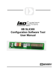
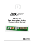
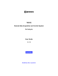
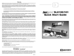
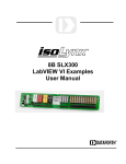
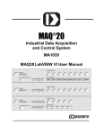
™
SLX200 LabVIEW VI Library
User Manual
isoLynx™ SLX200 LabVIEW VI Library Manual
isoLynx™ SLX200 LabVIEW VI Library User Manual
MA1028 Rev. A—March 2007
The information in this manual has been checked carefully and is believed to be accurate; however, Dataforth assumes
no responsibility for possible inaccuracies or omissions. Specifications are subject to change without notice.
© 2007 Dataforth Corporation. All rights reserved.
isoLynx is a trademark of Dataforth Corporation.
Microsoft, Windows, Windows XP, Visual Studio, Visual C++, Visual Basic, and Visual C# are trademarks or registered
trademarks of Microsoft Corporation.
LabVIEW, CVI, National Instruments, and ni.com are trademarks or registered trademarks of National Instruments
Corporation.
Revision History:
Revision
A
B
Date
3/8/07
3/13/07
Author
W Carr
W Carr
Description of Changes
Initial release
Minor corrections
i
isoLynx SLX200 LabVIEW VI Library User Manual
ii
Table of Contents
1.
Introduction..................................................................................................................................................... 1
1.1.
Overview................................................................................................................................................. 1
1.2.
Related Documentation........................................................................................................................... 1
1.3.
Files Required to Use the SLX200 LabVIEW Library........................................................................... 2
2. Terms You Should Know ............................................................................................................................... 3
2.1.
Ports and Devices.................................................................................................................................... 3
2.2.
Channel Numbers.................................................................................................................................... 3
3. Example VIs.................................................................................................................................................... 5
4. SLX200 Library VIs ....................................................................................................................................... 6
4.1.
Port-related VIs....................................................................................................................................... 6
4.1.1.
Open SLX RTU Port....................................................................................................................... 7
4.1.2.
Open SLX TCP Port ....................................................................................................................... 8
4.1.3.
Close SLX Port.vi ........................................................................................................................... 9
4.2.
Device-Related VIs............................................................................................................................... 10
4.2.1.
Open SLX Device ......................................................................................................................... 10
4.2.2.
Close SLX Device......................................................................................................................... 11
4.3.
Read/Write Analog/Digital Data VIs.................................................................................................... 12
4.3.1.
Read Analog Counts ..................................................................................................................... 13
4.3.2.
Write Analog Counts .................................................................................................................... 14
4.3.3.
Read Digital Data.......................................................................................................................... 15
4.3.4.
Write Digital Data......................................................................................................................... 16
4.4.
Other Routines ...................................................................................................................................... 17
4.4.1.
Read Status.................................................................................................................................... 17
4.4.2.
Read Error Registers ..................................................................................................................... 18
iii
isoLynx SLX200 LabVIEW VI Library User Manual
iv
About Dataforth Corporation
“Our passion at Dataforth Corporation is designing, manufacturing, and marketing the best possible
signal conditioning and data communication products. Our mission is setting new standards of
product quality, performance, and customer service.” Dataforth Corporation, with over 20 years
experience, is the worldwide leader in Instrument Class™ Industrial Electronics—rugged, high
performance signal conditioning and data communication products that play a vital role in maintaining
the integrity of industrial automation, data acquisition, and quality assurance systems. Our products
directly connect to most industrial sensors and protect valuable measurement and control signals and
equipment from the dangerous and degrading effects of noise, transient power surges, internal
ground loops, and other hazards present in industrial environments.
Dataforth spans the globe with over 50 International Distributors and US Representative Companies.
Our customers benefit from a team of over 130 sales people highly trained in the application of
precision products for industrial markets. In addition, we have a team of application engineers in our
Tucson factory ready to address and solve any in-depth application questions. Upon receipt of a
quote or order, our Customer Service Department provides fast one-day response of delivery
information. We maintain inventory that allows small quantity orders to be shipped from stock.
Contacting Dataforth Corporation
Contact Method
Contact Information
E-Mail:
Technical Support
[email protected]
Website:
www.dataforth.com
Phone:
520 704 1404 or 800 444 7644
Fax:
520 741 1404
Mail:
Dataforth Corporation
3331 E. Hemisphere Loop
Tucson, AZ 85706
Errata Sheets
Refer to the Technical Support area of Dataforth’s web site (www.dataforth.com) for any errata
information on this product.
v
isoLynx SLX200 LabVIEW VI Library User Manual
vi
1. Introduction
1.1. Overview
This manual describes the isoLynx SLX200 LabVIEW VI Library, which allows a user to access the
functions of the SLX200 from a user-written LabVIEW VI, as shown in Figure 1.1. The VI library is
built on top of the dynamic link library slxcom.dll. The VI library contains only a subset of the
functions available from slxcom.dll. This subset enables basic open, connect, status, and I/O
operations. Configuration of an isoLynx SLX200 is not possible with the LabVIEW VI library, but can
be accomplished by using the SlxConfig application supplied on the CD.
Three versions of the library are provided, slxcom_lv_6.1.llb, slxcom_lv_7.0.llb, slxcom_lv_8.0.llb; one
for each of LabVIEW versions 6.1, 7.0, and 8.0 (and above). LabVIEW versions prior to 6.1 are not
supported.
LabVIEW
7.0 VI
workstation
slxcom_lv_7.0.llb
LabVIEW 6.1
VI
slxcom_lv_6.1.llb
LabVIEW 8.0
VI
slxcom_lv_8.0.llb
slxcom.dll
Serial or Ethernet
connection
SLX200
Figure 1.1 SLX200 LabVIEW VI Library block diagram
1.2. Related Documentation
This document should be used in conjunction with the SLX200 API User Manual and the SLX200
Software User Manual. These manuals are on the CD that ships with the SLX200, and is also
available by download from the Dataforth web site.
1
isoLynx SLX200 LabVIEW VI Library User Manual
1.3. Files Required to Use the SLX200 LabVIEW Library
slxcom.dll – the dynamic link library the VI Library makes calls to. This file must be available to your
VI, by either being in the same folder or else in the current environment’s PATH.
The following files are the actual libraries and contain the SLX200 VIs needed to build your own
isoLynx SLX200 VIs. All of the following libraries contain the same VIs. They only differ in the
LabVIEW version they are targeted for.
slxcom_lv_6.1.llb - for LabVIEW 6.1 and above.
slxcom_lv_7.0.llb - for LabVIEW 7.0 and above.
slxcom_lv_8.0.llb – for LabVIEW 8.0 and above.
2
2. Terms You Should Know
2.1. Ports and Devices
In the SLX200 LabVIEW VI Library, a “port” represents the means of connection to the isoLynx(es),
such as a COM port or Ethernet connection. A “device” represents an isoLynx SLX200 (except in the
special case where an isoLynx has two Ethernet connectors, and each one is considered a device).
To use the library properly, the following steps must be done by your VI, in this order:
1) Open a port using either the Open SLX RTU Port or Open SLX TCP Port VI, depending on
whether your application is using Modbus RTU (serial line) or Modbus TCP (Ethernet).
2) Open a device using the Open SLX Device VI, passing it the port handle given by the VI in
step 1.
3) Use the other VIs in the library to send data to (and receive data from) the isoLynx, passing
each the device handle obtained in step 2.
4) When your VI has completed processing, close the device using the Close SLX Device VI,
passing it the device handle obtained in step 2.
5) Close the port using the Close SLX Port VI, passing it the port handle obtained in step 1.
See the example VIs on the CD, which demonstrate how to do these steps.
2.2. Channel Numbers
The SLX200 is a single-board system with optional expansion panels for additional digital and analog
channels. You can calculate a channel number based on the backpanel’s assigned address and the
channel’s position on the backpanel, as illustrated in the annotated block diagram below.
Channel numbers start at zero (for either digital or analog), and go up through the maximum number
available (63 is the highest analog channel using the maximum of three analog expansion panels,
and 127 is the highest digital channel using the maximum of eight digital panels). Each panel,
whether analog or digital, may contain up to 16 channels. The exception is the main (base) SLX200
panel, which has only 12 channels, numbered 0-11. A fully populated SLX200 system is shown
below in Figure 2.1.
3
isoLynx SLX200 LabVIEW VI Library User Manual
Jumpers on all J1
positions make this
digital panel 0; digital
channels 0-15.
Analog
channels 0-11
Jumpers on J1 pins 34 and 5-6 make this
digital panel 1; digital
channels 16-31.
A jumper across E1/E2
position 1 makes this
expansion panel 1;
analog channels 16-31.
A jumper across E1/E2
position 2 makes this
expansion panel 2;
analog channels 32-47.
A jumper across E1/E2
position 3 makes this
expansion panel 3;
analog channels 48-63.
No jumpers (or open)
on all J1 pins make this
digital panel 7; digital
channels 111-127.
Figure 2.1 SLX200 channel numbers
Perhaps the easiest way to figure channel numbers is to think in hexadecimal. Consider the high
nybble of the single-byte channel number to be the panel number, and the low nybble to be the
channel slot. For example, channel 0x41 refers to panel 4, slot 1 (the second slot from the left).
Other examples are shown in Figure 2.2 below. The “0x” indicates hexadecimal; 0x27 is decimal 39,
and 0x0A is decimal 10.
Channel numbers:
0x27 0x0A
panel #2
Figure 2.2 SLX200 channel number examples
4
slot #7
base unit
(panel 0)
slot #10
3. Example VIs
A number of example VIs are included on the CD as starting points for your own VI, several each for
LabVIEW 6.1, LabVIEW 7.0, and LabVIEW 8.0 (and above). The example VIs are very simple and
are intended to demonstrate use of the SLX200 LabVIEW VI library more so than to provide a
functional application.
5
isoLynx SLX200 LabVIEW VI Library User Manual
4. SLX200 Library VIs
4.1. Port-related VIs
These routines open and close the “port” (the means of connection to the SLX200).
In the following VIs, the “port handle” is a unique 32-bit identifier which specifies the port being used.
The “port handle” is initialized by either of the port-opening VIs, and is used later by the deviceopening VI. The user should not change the handle’s value. A port must be opened before making
the call to open a device.
6
4.1.1. Open SLX RTU Port
Open SLX RTU Port.vi
Opens a Modbus RTU port with the given communication parameters.
Connector Pane
Controls and Indicators
error in (no error) is a cluster that describes error conditions occurring before the VI
executes. If an error has already occurred, the VI passes the value of the error in cluster
to error out.
status is TRUE if an error occurred prior to the execution of this VI. If status is
TRUE, the VI does not do anything other than pass error in information to error
out.
code is the error code number identifying an error or warning. A value of 0
indicates no error, a negative value indicates a warning, and a positive value
indicates an error.
source identifies the name of the VI that produced the error.
port name (COM1) is a string indicating the serial port name (e.g. COM1, COM2, etc).
baud (19200) is the desired communication rate. Allowed values are 1200, 2400, 4800,
9600, 19200, 38400, 57600, and 115200.
parity (Even) is the desired serial parity.
error out is a cluster that contains error information. If the error in cluster indicated an
error, the error out cluster contains the same information. Otherwise, error out describes
the error status of this VI.
port handle is a handle to an isoLynx SLX200 RTU (serial) port. This output should be
wired to the identically named input terminal of one or more "Open SLX Device" VIs.
7
isoLynx SLX200 LabVIEW VI Library User Manual
4.1.2. Open SLX TCP Port
Open SLX TCP Port.vi
Opens a Modbus TCP port with the given communication parameters.
Connector Pane
Controls and Indicators
error in (no error) is a cluster that describes error conditions occurring before the VI
executes. If an error has already occurred, the VI passes the value of the error in cluster
to error out.
status is TRUE if an error occurred prior to the execution of this VI. If status is
TRUE, the VI does not do anything other than pass error in information to error
out.
code is the error code number identifying an error or warning. A value of 0
indicates no error, a negative value indicates a warning, and a positive value
indicates an error.
source identifies the name of the VI that produced the error.
server name is a string representing the domain name or IP address of the isoLynx
SLX200 system.
TCP port (502) is the desired server port to connect with. Current isoLynx SLX200
systems only communicate on TCP port 502 (the default), so it is safe to leave this
terminal unwired.
error out is a cluster that contains error information. If the error in cluster indicated an
error, the error out cluster contains the same information. Otherwise, error out describes
the error status of this VI.
port handle is a handle to an isoLynx SLX200 TCP port. This output should be wired to
the identically named input terminal of the "Open SLX Device" VI.
8
4.1.3. Close SLX Port.vi
Close SLX Port.vi
Closes an open isoLynx SLX200 port handle. The port handle is opened by a call to Open SLX RTU Port.vi or Open SLX
TCP Port.vi.
Connector Pane
Controls and Indicators
error in (no error) is a cluster that describes error conditions occurring before the VI
executes. If an error has already occurred, the VI passes the value of the error in cluster
to error out.
status is TRUE if an error occurred prior to the execution of this VI. If status is
TRUE, the VI does not do anything other than pass error in information to error
out.
code is the error code number identifying an error or warning. A value of 0
indicates no error, a negative value indicates a warning, and a positive value
indicates an error.
source identifies the name of the VI that produced the error.
port handle is a handle to an isoLynx SLX200 RTU (serial) or TCP port. Wire this input
to the handle obtained from the "Open SLX RTU Port" or "Open SLX TCP Port" VI.
error out is a cluster that contains error information. If the error in cluster indicated an
error, the error out cluster contains the same information. Otherwise, error out describes
the error status of this VI.
9
isoLynx SLX200 LabVIEW VI Library User Manual
4.2. Device-Related VIs
4.2.1. Open SLX Device
Open SLX Device.vi
Establishes a communication session with a single isoLynx SLX200 system. Either the Open SLX RTU Port or Open SLX
TCP Port VI must have run successfully before this VI is called.
Connector Pane
Controls and Indicators
error in (no error) is a cluster that describes error conditions occurring before the VI
executes. If an error has already occurred, the VI passes the value of the error in cluster
to error out.
status is TRUE if an error occurred prior to the execution of this VI. If status is
TRUE, the VI does not do anything other than pass error in information to error
out.
code is the error code number identifying an error or warning. A value of 0
indicates no error, a negative value indicates a warning, and a positive value
indicates an error.
source identifies the name of the VI that produced the error.
id (31) is the Modbus RTU Slave ID for an RTU port handle and the Modbus TCP Unit
ID for a TCP port handle. NOTE: isoLynx SLX200 ignores the Unit ID, so it is safe to use
a value of your choosing.
port handle is a handle to an isoLynx SLX200 RTU (serial) or TCP port. Wire this input
to the handle obtained from the "Open SLX RTU Port" or "Open SLX TCP Port" VIs.
error out is a cluster that contains error information. If the error in cluster indicated an
error, the error out cluster contains the same information. Otherwise, error out describes
the error status of this VI.
dev handle is a handle to an isoLynx SLX200 system. This output should be wired to
the identically named input terminals of other isoLynx SLX200 VIs.
10
4.2.2. Close SLX Device
Close SLX Device.vi
Closes an open isoLynx SLX200 device handle. The device handle is opened by a call to Open SLX Device.vi.
Connector Pane
Controls and Indicators
error in (no error) is a cluster that describes error conditions occurring before the VI
executes. If an error has already occurred, the VI passes the value of the error in cluster
to error out.
status is TRUE if an error occurred prior to the execution of this VI. If status is
TRUE, the VI does not do anything other than pass error in information to error
out.
code is the error code number identifying an error or warning. A value of 0
indicates no error, a negative value indicates a warning, and a positive value
indicates an error.
source identifies the name of the VI that produced the error.
dev handle is a handle to an isoLynx SLX200 system. Wire this input to the handle
obtained from the "Open SLX Device" VI.
error out is a cluster that contains error information. If the error in cluster indicated an
error, the error out cluster contains the same information. Otherwise, error out describes
the error status of this VI.
11
isoLynx SLX200 LabVIEW VI Library User Manual
4.3. Read/Write Analog/Digital Data VIs
For the following routines, additional information is available about the register values in the SLX200
Software User Manual sections 8-10. In each of the following routines, the arguments are defined as
follows:
1) dev handle – device handle obtained by call to Open SLX Device.vi.
2) type – either CURRENT, AVERAGE, MAX, or MIN. For the two “DigitalData” routines, the
type must be CURRENT.
3) chan – channel number
4) data or counts – array of boolean values (data) or 16-bit values (counts) to either read from or
write to the isoLynx
5) qty – number of 16-bit or boolean values to transfer
12
4.3.1. Read Analog Counts
Read Analog Counts.vi
Reads current, average, max, or min analog counts from the requested channel(s) on an isoLynx SLX200 system. The
device handle is obtained by a call to Open SLX Device.vi.
Connector Pane
Controls and Indicators
error in (no error) is a cluster that describes error conditions occurring before the VI
executes. If an error has already occurred, the VI passes the value of the error in cluster
to error out.
status is TRUE if an error occurred prior to the execution of this VI. If status is
TRUE, the VI does not do anything other than pass error in information to error
out.
code is the error code number identifying an error or warning. A value of 0
indicates no error, a negative value indicates a warning, and a positive value
indicates an error.
source identifies the name of the VI that produced the error.
dev handle is a handle to an isoLynx SLX200 system. Wire this input to the handle
obtained from the "Open SLX Device" VI.
data type selects either Current, Average, Maximum, or Minimum counts to be read from
the isoLynx SLX200 system.
chan is the channel ID of the first channel of a group of consecutive analog channels to
read from.
qty Is the number of consecutive analog channels to read, starting at the channel ID
given in chan.
error out is a cluster that contains error information. If the error in cluster indicated an
error, the error out cluster contains the same information. Otherwise, error out describes
the error status of this VI.
dev handle is a duplicate of the handle passed into the identically named input terminal.
This output can be wired to the identically named input terminals of other isoLynx
SLX200 VIs.
counts is an array of signed 16-bit values read from the isoLynx SLX200 system. The
data is in two's complement format where 32767 (hex 7FFF) corresponds to +10 volts
and -32768 (hex 8000) corresponds to -10 volts.
13
isoLynx SLX200 LabVIEW VI Library User Manual
4.3.2. Write Analog Counts
Write Analog Counts.vi
Writes current, average, max, or min analog counts to the requested channel(s) on an isoLynx SLX200 system. The
device handle is obtained by a call to Open SLX Device.vi.
Connector Pane
Controls and Indicators
error in (no error) is a cluster that describes error conditions occurring before the VI
executes. If an error has already occurred, the VI passes the value of the error in cluster
to error out.
status is TRUE if an error occurred prior to the execution of this VI. If status is
TRUE, the VI does not do anything other than pass error in information to error
out.
code is the error code number identifying an error or warning. A value of 0
indicates no error, a negative value indicates a warning, and a positive value
indicates an error.
source identifies the name of the VI that produced the error.
dev handle is a handle to an isoLynx SLX200 system. Wire this input to the handle
obtained from the "Open SLX Device" VI.
data type selects either Current, Average, Maximum, or Minimum counts to write to the
isoLynx SLX200 system. Use Average, Maximum, or Minimum to preset or reset the
corresponding analog input calculated values.
chan is the channel ID of the first channel of a group of consecutive analog channels to
write to. The quantity of channels written is equal to the size of the counts array input.
counts is an array of signed 16-bit values to write to the isoLynx SLX200 system. The
data is in two's complement format where 32767 (hex 7FFF) corresponds to +10 volts
and -32768 (hex 8000) corresponds to -10 volts.
error out is a cluster that contains error information. If the error in cluster indicated an
error, the error out cluster contains the same information. Otherwise, error out describes
the error status of this VI.
dev handle is a duplicate of the handle passed into the identically named input terminal.
This output can be wired to the identically named input terminals of other isoLynx
SLX200 VIs.
14
4.3.3. Read Digital Data
Read Digital Data.vi
Reads digital data from the requested channel(s) on an isoLynx SLX200 system. The device handle is obtained by a call
to Open SLX Device.vi.
Connector Pane
Controls and Indicators
error in (no error) is a cluster that describes error conditions occurring before the VI
executes. If an error has already occurred, the VI passes the value of the error in cluster
to error out.
status is TRUE if an error occurred prior to the execution of this VI. If status is
TRUE, the VI does not do anything other than pass error in information to error
out.
code is the error code number identifying an error or warning. A value of 0
indicates no error, a negative value indicates a warning, and a positive value
indicates an error.
source identifies the name of the VI that produced the error.
dev handle is a handle to an isoLynx SLX200 system. Wire this input to the handle
obtained from the "Open SLX Device" VI.
chan is the channel ID of the first channel of a group of consecutive digital channels to
read from.
qty Is the number of consecutive digital channels to read, starting at the channel ID given
in chan.
data type (current) has only one valid value (Current) for digital data. It is safe to leave
this terminal unwired.
error out is a cluster that contains error information. If the error in cluster indicated an
error, the error out cluster contains the same information. Otherwise, error out describes
the error status of this VI.
dev handle is a duplicate of the handle passed into the identically named input terminal.
This output can be wired to the identically named input terminals of other isoLynx
SLX200 VIs.
data is an array of boolean values read from the isoLynx SLX200 system.
15
isoLynx SLX200 LabVIEW VI Library User Manual
4.3.4. Write Digital Data
Write Digital Data.vi
Writes digital data to the requested channel(s) on an isoLynx SLX200 system. The device handle is obtained by a call to
Open SLX Device.vi.
Connector Pane
Controls and Indicators
error in (no error) is a cluster that describes error conditions occurring before the VI
executes. If an error has already occurred, the VI passes the value of the error in cluster
to error out.
status is TRUE if an error occurred prior to the execution of this VI. If status is
TRUE, the VI does not do anything other than pass error in information to error
out.
code is the error code number identifying an error or warning. A value of 0
indicates no error, a negative value indicates a warning, and a positive value
indicates an error.
source identifies the name of the VI that produced the error.
dev handle is a handle to an isoLynx SLX200 system. Wire this input to the handle
obtained from the "Open SLX Device" VI.
chan is the channel ID of the first channel of a group of consecutive digital channels to
write to. The quantity of channels written is equal to the size of the data array input.
data is an array of boolean values to write to the isoLynx SLX200 system.
data type (current) has only one valid value (Current) for digital data. It is safe to leave
this terminal unwired.
error out is a cluster that contains error information. If the error in cluster indicated an
error, the error out cluster contains the same information. Otherwise, error out describes
the error status of this VI.
dev handle is a duplicate of the handle passed into the identically named input terminal.
This output can be wired to the identically named input terminals of other isoLynx
SLX200 VIs.
16
4.4. Other Routines
For the following routines, additional information is available about the register values in the SLX200
Software User Manual section 13.
4.4.1. Read Status
Read Status.vi
Reads the status register from an open isoLynx SLX200 system. The device handle is obtained by a call to Open SLX
Device.vi.
Connector Pane
Controls and Indicators
error in (no error) is a cluster that describes error conditions occurring before the VI
executes. If an error has already occurred, the VI passes the value of the error in cluster
to error out.
status is TRUE if an error occurred prior to the execution of this VI. If status is
TRUE, the VI does not do anything other than pass error in information to error
out.
code is the error code number identifying an error or warning. A value of 0
indicates no error, a negative value indicates a warning, and a positive value
indicates an error.
source identifies the name of the VI that produced the error.
dev handle is a handle to an isoLynx SLX200 system. Wire this input to the handle
obtained from the "Open SLX Device" VI.
error out is a cluster that contains error information. If the error in cluster indicated an
error, the error out cluster contains the same information. Otherwise, error out describes
the error status of this VI.
dev handle is a duplicate of the handle passed into the identically named input terminal.
This output can be wired to the identically named input terminals of other isoLynx
SLX200 VIs.
status bits indicate individual error conditions detected by the power-on self-test.
DAC Failure is TRUE if a DAC failure was detected.
ADC Failure is TRUE if an ADC failure was detected.
EEPROM Failure is TRUE if a EEPROM failure was detected.
SRAM Failure is TRUE if an SRAM failure was detected.
ok is TRUE if power-on self-test completed successfully.
17
isoLynx SLX200 LabVIEW VI Library User Manual
4.4.2. Read Error Registers
Read Error Registers.vi
Reads the error registers from an open isoLynx SLX200 system.
Connector Pane
Controls and Indicators
error in (no error) is a cluster that describes error conditions occurring before the VI
executes. If an error has already occurred, the VI passes the value of the error in cluster
to error out.
status is TRUE if an error occurred prior to the execution of this VI. If status is
TRUE, the VI does not do anything other than pass error in information to error
out.
code is the error code number identifying an error or warning. A value of 0
indicates no error, a negative value indicates a warning, and a positive value
indicates an error.
source identifies the name of the VI that produced the error.
dev handle is a handle to an isoLynx SLX200 system. Wire this input to the handle
obtained from the "Open SLX Device" VI.
error out is a cluster that contains error information. If the error in cluster indicated an
error, the error out cluster contains the same information. Otherwise, error out describes
the error status of this VI.
dev handle is a duplicate of the handle passed into the identically named input terminal.
This output can be wired to the identically named input terminals of other isoLynx
SLX200 VIs.
error information provides more information about an error condition. See the SLX200
Software User Manual for more information.
error code is zero if no error condition exists. See the SLX200 Software User Manual for
a description of other error codes.
18