1
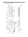
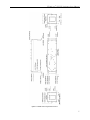
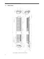
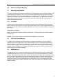
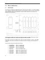
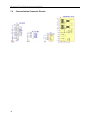
8B SLX300 Data Acquisition System Hardware User Manual 8B isoLynx® SLX300 Hardware User Manual ® 8B isoLynx SLX300 Data Acquisition System Hardware User Manual MA1031 Rev. A – July 2010 © 2010 Dataforth Corporation. All Rights Reserved. The information in this manual has been checked carefully and is believed to be accurate; however, Dataforth assumes no responsibility for possible inaccuracies or omissions. Specifications are subject to change without notice. The information, tables, diagrams, and photographs contained herein are the property of Dataforth Corporation. No part of this manual may be reproduced or distributed by any means, electronic, mechanical, or otherwise, for any purpose other than the purchaser’s personal use, without the express written consent of Dataforth Corporation. isoLynx® is a registered trademark of Dataforth Corporation. Windows® is a registered trademark of Microsoft Corporation. LabVIEW™ is a trademark of National Instruments Corporation. Modbus® is a registered trademark of the Modbus Organization, Inc. ii 8B isoLynx® SLX300 Hardware User Manual Table of Contents 1.0 Inspection Guidelines ........................................................................................................................ 1 1.1 Unpacking ..................................................................................................................................... 1 1.2 8B isoLynx® SLX300 Unit Package Contents ............................................................................... 1 2.0 System Overview .............................................................................................................................. 2 2.1 Easy Installation ............................................................................................................................ 2 2.2 Easy Connectivity and Communication ........................................................................................ 2 2.2.1 RS-232 .................................................................................................................................. 2 2.2.2 RS-485 .................................................................................................................................. 3 2.2.3 USB ....................................................................................................................................... 3 2.2.4 Ethernet ................................................................................................................................. 3 2.2.5 Communication Interface Reset Jumper ............................................................................... 3 3.0 Dimensions and Mounting Considerations ....................................................................................... 5 3.1 19” Cabinet Mount or Panel Mount ............................................................................................... 6 3.2 DIN Rail Mount .............................................................................................................................. 8 8B isoLynx® SLX300 Controller ........................................................................................................ 9 4.0 4.1 Indicators: LEDs ............................................................................................................................ 9 4.1.1 Power .................................................................................................................................... 9 4.1.2 Ethernet ................................................................................................................................. 9 4.1.3 Communication ..................................................................................................................... 9 4.1.4 Status .................................................................................................................................... 9 4.2 Slave ID Selection ......................................................................................................................... 9 4.2.1 5.0 Modbus RTU Slave ID Selection.............................................................................................. 9 Analog and Digital Modules ............................................................................................................ 11 5.1 8B Analog Input Modules ............................................................................................................ 11 5.1.1 CJC Jumper ........................................................................................................................ 11 5.2 8B Analog Output Modules ......................................................................................................... 11 5.3 SCMD Modules ........................................................................................................................... 11 6.0 6.1 7.0 Power Considerations ..................................................................................................................... 12 Power Supply .............................................................................................................................. 12 Communication Connector Pinouts ................................................................................................ 14 iii 8B isoLynx® SLX300 Hardware User Manual About Dataforth Corporation “Our passion at Dataforth Corporation is designing, manufacturing, and marketing the best possible signal conditioning, data acquisition, and data communication products. Our mission is to set new standards of product quality, performance, and customer service.” Dataforth Corporation, with more than a quarter century of experience, is the worldwide leader in Instrument Class® Industrial Electronics – rugged, high performance signal conditioning, data acquisition, and data communication products that play a vital role in maintaining the integrity of industrial automation, data acquisition, and quality assurance systems. Our products directly connect to most industrial sensors and protect valuable measurement and control signals and equipment from the dangerous and degrading effects of noise, transient power surges, internal ground loops, and other hazards present in industrial environments. Dataforth spans the globe with more than 50 International Distributors and US Representative Companies. Our customers benefit from a team of over 130 sales people highly trained in the application of precision products for industrial markets. In addition, we have a team of application engineers in our Tucson factory ready to solve any in-depth application questions. Upon receipt of a quote or order, our Customer Service Department provides fast one-day delivery information turnaround. We maintain an ample inventory that allows small quantity orders to be shipped from stock. Contacting Dataforth Corporation Contact Method E-Mail: Technical Support Website: Phone: Fax: Mail: Contact Information [email protected] www.dataforth.com 520-741-1404 and toll free 800-444-7644 520-741-0762 Dataforth Corporation 3331 E. Hemisphere Loop Tucson, AZ 85706 Errata Sheets Refer to the Technical Support area of Dataforth’s website (www.dataforth.com) for any errata information on this product. iv 8B isoLynx® SLX300 Hardware User Manual 1.0 Inspection Guidelines 1.1 Unpacking Each 8B isoLynx® SLX300 unit is shipped in electro-static discharge (ESD) protective packaging. Use appropriate ESD protection measures while unpacking. Check visually for physical damage. If physical damage is noted, file a claim with the shipping carrier. 1.2 8B isoLynx® SLX300 Unit Package Contents • 8B isoLynx® SLX300, p/n SLX300-10, -10D, -20, -20D, -30, -30D, -40, or -40D • SLX147-01 USB Cable, Type A to Type B, 1m (included with SLC300-30, -30D only) • CD-ROM which contains o SLX370 Software Tools Configuration Sample LabVIEW VIs Programming Samples in Visual Basic, VB.NET, C++ and C# Windows Driver for USB Interface o SLX380 Documentation Set MA1029 SLX300 Configuration Software Tool User Manual MA1030 SLX300 Quick Start Guide MA1031 SLX300 Hardware User Manual (this manual) MA1032 SLX300 Software User Manual MA1033 SLX300 LabVIEW VI Examples User Manual This completes the unpacking and visual inspection of the 8B isoLynx® SLX300 unit. For rapid verification of basic functionality, reference the 8B isoLynx® SLX300 Quick Start Guide. For detailed instructions on installation and configuration in your system, reference the subsequent sections in this 8B isoLynx® SLX300 Hardware User Manual and/or the 8B isoLynx® SLX300 Software User Manual on CD-ROM. 1 8B isoLynx® SLX300 Hardware User Manual 2.0 System Overview The 8B isoLynx® SLX300 is a fast, intelligent, fully isolated data acquisition system providing superior reliability, accuracy, and isolation for a wide range of rugged industrial applications. The flexible, modular design combines eight SCMD digital I/O channels, four 8B analog output channels and twelve 8B analog input channels into one single board. The 8B isoLynx® implements the industry standard Modbus RTU and TCP protocols, thereby enabling communication with a wide variety of existing third-party software drivers and HMI/SCADA packages. Dataforth offers a Windows based, free Configuration Software Tool which makes it easy to make a few basic system connections and quickly start taking measurements. The 8B isoLynx® is factory configured to communicate to a host PC using RS-232, RS-485, or USB serial links or Ethernet as its physical layer. Up to 16 systems can be multi-dropped on the RS-485 serial link. 2.1 Easy Installation The 8B isoLynx® SLX300’s compact footprint (16.235” x 3.47”) allows it to fit easily into cramped system designs. Using the SCMXRK-002 metal bracket, it can be quickly mounted in industry standard 19” racks. Alternatively, by ordering DIN rail hardware elements, it can be just as readily mounted on a DIN rail. 2.2 Easy Connectivity and Communication The 8B isoLynx® SLX300 system comes with one of four possible communication connectors, depending on the configuration of the board: RS-232 (DB9 Male), RS-485 (5-Pin Header with pluggable mating connector), USB (Type B), or Ethernet (RJ-45). The following is a detailed description of the connectors and default parameters for the communication settings. The default communication parameters are split into two categories: Serial and Ethernet. Serial applies to RS-232, RS-485, and USB. The parameters are: 2.2.1 Parameter Factory Default Setting Serial Data Rate Parity Slave ID 4-Wire Termination RS-232, RS-485, and USB 115,200bps (bits per second) Even 16 (0x10) 4-wire (pertains only to RS-485) Disabled (pertains only to RS-485) Ethernet IP Address Subnet Mask Gateway TCP Port 192.168.128.100 255.255.0.0 127.0.0.1 502 RS-232 The RS-232 Serial connector is a DB9 Male. Serial cables offered as accessories which can be used with the system are: SLX146-02 Null Modem Female DB-9 to Female DB-9 2m (5 ft) and SLX146-07 Null Modem Female DB-9 to Female DB-9 7m (25 ft). Refer to Section 7.0 Communication Connector Pinouts for RS-232 connector pinout. 2 8B isoLynx® SLX300 Hardware User Manual 2.2.2 RS-485 The RS-485 Serial connector is a 5-pin header with 5.08mm spacing. A vertical entry pluggable mating connector is provided to interface to this connector. Refer to Section 7.0 Communication Connector Pinouts for RS-485 connector pinout. RS-485 Termination: In general for RS-485 trunk line lengths over 100 ft (30.5m), the two devices at the extreme ends of the trunk line should be terminated and all other devices in between should not be terminated. The 8B isoLynx® SLX300 system offers built-in terminations for 2-wire and 4-wire networks accessed through a register address via Modbus command (refer to the 8B isoLynx® SLX300 Software Manual). Default configuration is RS-485 Termination Disabled. Four-wire Networks: When using the RS-485 Serial connector, the factory default mode of operation is 4-wire. Two-wire Networks: This mode uses only the TX+ and TX- pins of the RS-485 Serial connector. This mode is selected through a register address accessed via Modbus command (refer to the 8B isoLynx® SLX300 Software Manual). Once this selection is made, the system must be rebooted for the change to take effect. 2.2.3 USB The USB Serial connector is a Type B. Any Type A to Type B cable can be used provided the cable does not exceed 15’ in length. USB cables offered as accessories which can be used with the system are: SLX147-01 Type A to Type B 1m, SLX147-02 Type A to Type B 2m, and SLX147-05 Type A to Type B 5m. When using this interface the user must install a Windows driver which is provided on the CD-ROM shipped with the unit, so that when the connection is made the computer will see a virtual Serial COM port. The user must know the COM port number assigned by the computer to the USB virtual Serial COM port as it will be requested by the SLX300 Configuration Software when initiating communication. Refer to Section 7.0 Communication Connector Pinouts for USB connector pinout. 2.2.4 Ethernet This interface is compatible with 10Base-T Ethernet or 10/100Base-T networks. Connecting to Ethernet is as easy as inserting one end of a cable with RJ-45 modular phone plug into the modular phone jack on the 8B isoLynx® SLX300 and then inserting the other end with RJ-45 modular phone plug into a modular phone jack at the Ethernet hub or host computer, if so equipped. The Ethernet connection should always be made using a Category 5 twisted-pair cable. Ethernet cables offered as accessories which can be used with the system are SLX141-01 (1m), SLX141-02 (2m), and SLX141-07 (7m). Crossover cables are also offered with part numbers SLX141-X01 (1m), SLX141-X02 (2m), and SLX141-X07 (7m). It is up to the user to determine if straight through or crossover cables are required in a given application. Refer to Section 7.0 Communication Connector Pinouts for Ethernet connector pinout and connector details. The host computer Ethernet port must be configured with a fixed IP Address of 192.168.xxx.xxx, which does not match the static IP Address of the SLX300, and Subnet Mask of 255.255.0.0 when the 8B isoLynx® SLX300 Ethernet port is used. 2.2.5 Communication Interface Reset Jumper For situations in which the 8B isoLynx® has been put into a state with unknown communication parameters (i.e., baud rate, RS-485 4-wire, RS-485 2-wire), a hardware reset jumper has been provided. This jumper is located at the top left side of the board, in line with the +5V power connector, and is labeled RESET as shown in Figure 1 below. Placing the mini-link shunt jumper over pins 1 and 2 and cycling power will reset the board to its factory default communication parameters as listed in Section 2.2 3 8B isoLynx® SLX300 0 Hardware User U Manua al nnectivity and Communicattion. Once the board has completed c bo oot up, the mini-link shunt Easy Con jumper ovver pins 1 and d 2 can be rem moved and pllaced over pin ns 2 and 3. Figure 1: Reset Jumperr Location 4 8B isoLynx® SLX300 Hardware User Manual 3.0 Dimensions and Mounting Considerations The 8B isoLynx® SLX300 system has two mounting options. Models with no letter suffix are intended to be mounted in an industry standard 19” cabinet using the SCMXRK-002 metal mounting rack, or on a flat surface such as a NEMA-rated electrical enclosure using screws inserted through the swaged standoffs on the 8B isoLynx® SLX300. Models with a D suffix can be mounted on an industry standard 35 x 7.5 or 35 x 15 gull-wing DIN rail. DIN rail is offered as an accessory under part numbers SCMXRAIL1-01 or -02 (DIN EN50022-35x7.5) or SCMXRAIL2-01 or -02 (DIN EN50022-35x15), where the suffix indicates rail length in meters. Sections 3.1 19” Cabinet Mount or Panel Mount and 3.2 DIN Rail Mount show the dimensions and mounting options for the 8B isoLynx® SLX300 system. Be sure to select a mounting location that avoids or protects against the following environmental hazards: • Flying metal chips that may result from installation or subsequent machine construction and conductive dusts, liquids, or condensing humidity. If any of these conditions exist, mount the 8B isoLynx® SLX300 system and expansion components in a NEMA 4 or NEMA 12 rated enclosure. • Mounting locations that are in close proximity to devices that produce Electromagnetic Interference (EMI) or Radio Frequency Interference (RFI). Devices such as motor starters, relays, large power transformers, and ultrasonic welding apparatus fall into this category. Although the 8B isoLynx® SLX300 system is designed to work in such conditions, best performance is obtained when the system is mounted in a shielded enclosure with a solid connection to earth ground. 5 8B isoLynx® SLX300 Hardware User Manual 3.1 19” Cabinet Mount or Panel Mount ® Figure 2: 8B isoLynx SLX300 Block Diagram 6 8B issoLynx® SLX X300 Hardw ware User Ma anual Figu ure 3: SCMXRK--002 Analog Racck Dimensions 7 8B isoLynx® SLX300 0 Hardware User U Manua al 3.2 D Rail Mou DIN unt ® Figure 4: 8B issoLynx SLX300 0 DIN Rail Mountt Assembly 8 8B isoLynx® SLX300 Hardware User Manual 4.0 8B isoLynx® SLX300 Controller 4.1 Indicators: LEDs 4.1.1 Power LEDs located next to the power input terminal blocks will light up when power is applied. The system can be powered from a 5VDC ±5% source applied to the Main Power terminal block, or it can be powered from a 7 to 34VDC source applied to the Alternate Power terminal block. When the Alternate Power input is used, an 8BPWR-2 module must be installed in the socket above the Alternate Power terminal block. 4.1.2 Ethernet An LED on the PCB next to the Ethernet connector indicates Ethernet status. When an Ethernet cable is properly connected, the ETH STAT LED will blink at a 1 second interval. Additionally, there are two LEDs integrated in the Ethernet connector which light to indicate LINK and ACT status. 4.1.3 Communication RX and TX LEDs located at the top left corner of the board are used to indicate communication between the host computer and the 8B isoLynx® SLX300 system over any of the communication ports: RS-232, RS-485, USB or Ethernet. The RX LED will light up anytime a command from the host computer is received by the 8B isoLynx® SLX300 system and the TX LED will light up anytime a response from the 8B isoLynx® SLX300 is sent to the host computer. 4.1.4 Status Located in the middle of the board, these LEDs are: STATUS, CFG (Configuration), SCN (Continuous Scan), BUF (Buffer Scan), and ALARM. • STATUS LED: Blinks at a 1 second interval to indicate system status is normal and system is operational. When in Buffer Scan mode, the STATUS LED will remain in the state it was in when the mode was entered until the Buffer Scan has completed. • CFG LED: Lights when Configuration Mode is selected. • SCN LED: Lights when Continuous Scan Mode is selected. • BUF LED: Lights when Buffer Scan Mode is selected. • ALARM LED: Lights when an alarm condition has been reached. After power up, the system will default to the Configuration Mode. 4.2 Slave ID Selection 4.2.1 Modbus RTU Slave ID Selection The lower four bits of the Modbus RTU Slave ID are set using the jumpers located above the 5V Power connector as shown in Figure 5 below. The four jumpers allow 16 addresses. The LSB (Least Significant Bit) is the jumper on the right, designated LSB on the PCB. A mini-link shunt jumper placed over both pins of any jumper position corresponds to a 0 (zero) in the address, and a mini-link jumper placed over only one pin or completely removed in any jumper position corresponds to a 1 (one) in the address. To 9 8B isoLynx® SLX300 0 Hardware User U Manua al e lower four bits of a particu ular Slave ID,, arrange jum mpers in the biinary weighted pattern of th he obtain the value dessired as shown in Table 1. Figure 5: Location of Slave ID Jumperss Table 1: Slave ID Jumper Locatiion vs. Address MSB 1 1 1 1 0 0 0 0 1 1 LSB 1 0 Slave ID 31 30 **** 0 1 0 0 0 = Jumper In 1 = Jumper Out 17 16 d 0000 (decim mal = 0). The upper four bits are 0001 The factory default settting is all jumpers installed 1 so the resulting factoryy default Slavve ID is 0001 0000 (decima al = 16). The e upper four bits b (decimal 16), cannot be e changed. 10 8B isoLynx® SLX300 Hardware User Manual 5.0 Analog and Digital Modules 5.1 8B Analog Input Modules The twelve channels on the right end of the 8B isoLynx® SLX300 system are intended for SensorLex® 8B Isolated Analog Input Modules. These channels are labeled ANALOG IN inside the 8B module outline. Refer to the 8B isoLynx® SLX300 system datasheet for available modules. Only 8B input modules with a unipolar 0 to 5V output can be used in the 8B isoLynx® SLX300 system. The system has over-range clamps and protection but the use of a module with output range beyond this limit may damage the system after prolonged operation. 5.1.1 CJC Jumper A 2-pin jumper is located between each analog input channel and the field side terminal blocks; this is used to connect or disconnect the CJC sensor from the 8B input module. Default configuration from the factory is CJC sensor connected to the 8B module with a mini-link shunt jumper installed over both pins of each jumper. Jumper usage is as follows: 8B30/31/32/33/34/36/37/39/40/41/42/43/45/47/49/50/51/PT – Mini-link shunt jumper remains installed over both pins. 8B35/38 – Mini-link shunt jumper must be removed and installed over one pin only. 5.2 8B Analog Output Modules To the left of the analog input channels there are four analog output channels. These are labeled ANALOG OUT inside the 8B module outline. Refer to the 8B isoLynx® SLX300 system datasheet for available modules. Only 8B output modules with a unipolar 0 to 5V input can be fully utilized in the 8B isoLynx® system. Modules with a wider input range can be used but the full output range will not be available. Alarm conditions can be mapped to the analog output channels. Refer to the 8B isoLynx® SLX300 Software User Manual for details. 5.3 SCMD Modules The eight channels on the left end of the 8B isoLynx® SLX300 system accept industry standard SCMD miniature solid-state relay modules. Refer to the 8B isoLynx® SLX300 system datasheet for available modules. Each channel is protected with a 4A/250V fuse between the module and the field side terminal block. An extra fuse is provided next to the communication connectors. Many high-level functions are provided using the digital input/output channels, including pulse/frequency counter, pulse/frequency counter with de-bounce, waveform measurement, time between events, frequency generator, PWM generator, one-shot pulse generator, and alarm output. Refer to the 8B isoLynx® SLX300 Software User Manual for details. 11 8B isoLynx® SLX300 0 Hardware User U Manua al 6.0 P Power Cons siderations s 6.1 P Power Supply The 8B isoLynx® SLX3 300 can be po owered by eith her +5VDC ±5% (Main Pow wer) or 7 to 34VDC 3 (Altern nate S term minal blocks are a provided for f each powe er input as shown in Figure e 6. When a wide w Power). Separate range 7 to o 34VDC source is used, an a 8BPWR-2 module mustt be installed in i the socket above the Alternate Power termin nal block. Figure 6: Power Supply y Terminal Blockss onnected to both b power inp puts to provid de redundant power. When n If desired,, power suppllies can be co power is applied a to botth inputs, internal circuitry will w select the e +5VDC sourrce. A typical at +5 5VDC and 320mA typical at a 7 to 34VDC C. Total syste em Base systtem current draw is 270mA current drraw must take e into accountt the current draw d from the e user’s choicce of analog and a digital I/O modules. d as accessorries are as folllows: Power supplies offered 12 • • • • • SCMXPRT T-001 SCMXPRE E-001 SCMXPRT T-003 SCMXPRE E-003 PWR-4505 5 5VDC, 1A, 120V VAC Input 5VDC, 1A, 220V VAC Input 5VDC, 3A, 120V VAC Input 5VDC, 3A, 220V VAC Input 5VDC, 5A, 85-264VAC Input • • • • PWR-PS5RB PWR-PS5RC PWR-PS5RD PWR-PS5RE 24V VDC, 0.6A, 10 00-240VAC Input 24V VDC, 1.3A, 10 00-240VAC Input 24V VDC, 2.1A, 10 00-240VAC Input 24V VDC, 4.2A, 10 00-240VAC Input 8B isoLynx® SLX300 Hardware User Manual When the 7 to 34VDC Alternate Power is used in conjunction with the 8BPWR-2 7-34VDC to 5VDC converter module, the maximum output which the 8BPWR-2 can provide is 2A. The user must ensure that the system population with analog and digital I/O modules does not exceed this limitation. 13 8B isoLynx® SLX300 Hardware User Manual 7.0 14 Communication Connector Pinouts 8B isoLynx® SLX300 Hardware User Manual DATAFORTH WARRANTY Applying to Products Sold by Dataforth Corporation a. General. Dataforth Corporation (“Dataforth”) warrants that its products furnished under this Agreement will, at the time of delivery, be free from defects in material and workmanship and will conform to Dataforth's applicable specifications or, if appropriate, to buyer's specifications accepted in writing by Dataforth. DATAFORTH'S OBLIGATION OR LIABILITY TO BUYER FOR PRODUCTS WHICH DO NOT CONFORM TO THE ABOVE STATED WARRANTY SHALL BE LIMITED TO DATAFORTH, AT DATAFORTH'S SOLE DISCRETION, EITHER REPAIRING, REPLACING, OR REFUNDING THE PURCHASE PRICE OF THE DEFECTIVE PRODUCT(S) PROVIDED THAT WRITTEN NOTICE OF SAID DEFECT IS RECEIVED BY DATAFORTH WITHIN THE TIME PERIODS SET FORTH BELOW: i. for all software products including licensed programs, thirty (30) days from date of initial delivery; government, or governmental agency of any country resulting directly or indirectly (i) from any acts not authorized by Dataforth in writing or any statements regarding the products inconsistent with Dataforth's product documentation or standard warranty, or (ii) from any breach or threatened breach by buyer, or by any of its employees or agents, of any term, condition or provision of this Warranty or (iii) from any warranty, representation, covenant or obligation given by buyer to any third party and not expressly provided for in this Warranty or (iv) for any non-compliance (in any form) of the products with any necessary or mandatory applicable laws, regulations, procedures, government or industry policies or requirements related to the use, sale or importation of the products. Such indemnification shall include the payment of all reasonable attorneys' fees and other costs incurred by Dataforth in defending such claim. c. ii. for all hardware products including complete systems, one (1) year from date of initial delivery; iii. for all special products, sixty (60) days from date of initial delivery; and further, all products warranted hereunder for which Dataforth has received timely notice of nonconformance must be returned FOB to Dataforth's plant in Tucson, Arizona USA within thirty (30) days after the expiration of the warranty periods set forth above. The foregoing warranties shall not apply to any products which Dataforth determines have, by buyer or otherwise, been subjected to operating and/or environmental conditions in excess of the maximum value established therefor in the applicable specifications, or any products that have been the subject of mishandling, misuse, misapplication, neglect, improper testing, repair, alteration or damage. THE PROVISIONS OF THE FOREGOING WARRANTIES EXTEND TO BUYER ONLY AND NOT TO BUYER'S CUSTOMERS OR USERS OF BUYER'S PRODUCTS. THE DATAFORTH STANDARD WARRANTY IS IN LIEU OF ALL WARRANTIES OF MERCHANTABILITY AND FITNESS FOR A PARTICULAR PURPOSE OR USE AND ALL OTHER WARRANTIES WHETHER EXPRESS, IMPLIED OR STATUTORY, EXCEPT AS TO TITLE. THE DATAFORTH STANDARD WARRANTY MAY BE CHANGED BY DATAFORTH WITHOUT NOTICE. b. Buyer Indemnity. Buyer agrees to indemnify and hold Dataforth harmless from and against any and all claims, damages and liabilities whatsoever asserted by any person, entity, industry organization, Limitation on Damages. (1) IN NO EVENT SHALL DATAFORTH, ITS SUPPLIERS, LICENSORS, SERVICE PROVIDERS, EMPLOYEES, AGENTS, OFFICERS, AND DIRECTORS BE LIABLE FOR INDIRECT, SPECIAL, INCIDENTAL, COVER, ECONOMIC, PUNITIVE, ACTUAL, EXEMPLARY, CONSEQUENTIAL OR OTHER DAMAGES OF ANY NATURE INCLUDING, WITHOUT LIMITATION, LOST PROFITS OR REVENUES, COSTS OF REPLACEMENT PRODUCTS, LOSS OR DAMAGE TO DATA ARISING OUT OF THE USE OR INABILITY TO USE ANY DATAFORTH PRODUCT. (2) IN NO EVENT SHALL DATAFORTH BE LIABLE FOR DIRECT, SPECIAL, INDIRECT, INCIDENTAL OR CONSEQUENTIAL DAMAGES OF ANY NATURE RESULTING FROM BUYER’S NONCOMPLIANCE (IN ANY FORM) WITH ALL NECESSARY OR MANDATORY APPLICABLE LAWS, REGULATIONS, PROCEDURES, GOVERNMENT POLICIES OR REQUIREMENTS RELATED TO THE USE, SALE OR IMPORTATION OF PRODUCTS. (3) IN NO EVENT WILL THE COLLECTIVE LIABILITY OF DATAFORTH AND ITS SUPPLIERS, LICENSORS, SERVICE PROVIDERS, EMPLOYEES, AGENTS, OFFICERS, AND DIRECTORS TO ANY PARTY (REGARDLESS OF THE FORM OF ACTION, WHETHER BASED UPON WARRANTY, CONTRACT, TORT, OR OTHERWISE) EXCEED THE GREATER OF EITHER US$1000.00 (ONE THOUSAND DOLLARS U.S.A. CURRENCY) OR THE AMOUNT PAID TO DATAFORTH FOR THE APPLICABLE PRODUCT OR SERVICE OUT OF WHICH LIABILITY AROSE. 15 8B isoLynx® SLX300 Hardware User Manual (4) DATAFORTH’S LIABILITY ARISING OUT OF THE PRODUCTION, SALE OR SUPPLY OF PRODUCTS OR THEIR USE OR DISPOSITION, WHETHER BASED UPON WARRANTY, CONTRACT, TORT OR OTHERWISE, SHALL NOT EXCEED THE GREATER OF EITHER US$1000.00 (ONE THOUSAND DOLLARS U.S.A. CURRENCY) OR THE ACTUAL PURCHASE PRICE PAID BY BUYER FOR DATAFORTH'S PRODUCTS. DATAFORTH'S LIABILITY FOR ANY CLAIM OF ANY KIND SHALL IN NO CASE EXCEED THE OBLIGATION OR LIABILITY SPECIFIED IN THIS WARRANTY. d. Technical Assistance. Dataforth 's Warranty as hereinabove set forth shall not be enlarged, diminished or affected by, and no obligation or liability shall arise or grow out of, Dataforth's rendering of technical advice, facilities or service in connection with buyer's order of the products furnished hereunder. e. Warranty Procedures. Buyer shall notify Dataforth of any products which it believes to be defective during the applicable warranty period and which are covered by the Warranty set forth above. Buyer shall not return any products for any reason without the prior authorization of Dataforth and issuance of a Return Material Authorization ("RMA") number. After issuance of a RMA number, such products shall be promptly returned by buyer (and in no event later than thirty (30) days after the Warranty expiration date), transportation and insurance prepaid, to Dataforth's designated facility for examination and testing. Dataforth shall either repair or replace any such products found to be so defective and promptly return such products to buyer, transportation and insurance prepaid. Should Dataforth's examination and testing not disclose any defect covered by the foregoing Warranty, Dataforth shall so advise buyer and dispose of or return the products in accordance with buyer's instructions and at buyer's sole expense, and buyer shall reimburse Dataforth for testing expenses incurred at Dataforth's then current repair rates. f. Repair Warranty. Dataforth warrants its repair work and/or replacement parts for a period of ninety (90) days from receipt by buyer of the repaired or replaced products or for the remainder of the warranty period for the initial delivery of such order as set forth in paragraph a above, whichever is greater. g. Critical Applications. Certain applications using Dataforth's products may involve potential risks of death, personal injury, or severe property or environmental damage ("Critical Applications"). DATAFORTH'S PRODUCTS ARE NOT DESIGNED, INTENDED, AUTHORIZED, OR WARRANTED TO BE SUITABLE FOR USE IN LIFE-SUPPORT DEVICES OR SYSTEMS, SAFETY EQUIPMENT, NUCLEAR FACILITY APPLICATIONS OR OTHER CRITICAL APPLICATIONS WHERE MALFUNCTION OF THE PRODUCT CAN BE EXPECTED TO RESULT IN PERSONAL INJURY, DEATH OR SEVERE PROPERTY DAMAGE. BUYER USES OR SELLS SUCH PRODUCTS FOR USE IN SUCH CRITICAL APPLICATIONS AT BUYER'S OWN RISK AND AGREES TO DEFEND, INDEMNIFY AND HOLD HARMLESS DATAFORTH FROM ANY AND ALL DAMAGES, CLAIMS, PROCEEDINGS, SUITS OR EXPENSE RESULTING FROM SUCH USE. h. Static Sensitive. Dataforth ships all product in anti-static packages. Dataforth's Warranty as hereinabove set forth shall not cover warranty repair, replacement, or refund on product or devices damaged by static due to buyer's failure to properly ground. _____________________________________________________________________________________________ Application Support Dataforth provides timely, high-quality product support. Call 1-800-444-7644 TOLL-FREE. Returns/Repair Policy All warranty and repair requests should be directed to the Dataforth Customer Service Department at (520) 741-1404. If a product return is required, request a Return Material Authorization (RMA) number. You should be ready to provide the following information: 1. Complete product model number. 2. Product serial number. 3. Name, address, and telephone number of person returning product. 4. Special repair instructions. 5. Purchase order number for out-of-warranty repairs. 16 8B isoLynx® SLX300 Hardware User Manual The product should be carefully packaged, making sure the RMA number appears on the outside of the package, and ship prepaid to: Dataforth Corporation 3331 E. Hemisphere Loop Tucson, AZ 85706 USA The information provided herein is believed to be reliable; however, DATAFORTH assumes no responsibility for inaccuracies or omissions. DATAFORTH assumes no responsibility for the use of this information, and all use of such information shall be entirely at the user's own risk. Application information is intended as suggestions for possible use of the products and not as explicit performance in a specific application. Prices and specifications are subject to change without notice. No patent rights or licenses to any of the circuits described herein are implied or granted to any third party. DATAFORTH does not authorize or warrant any DATAFORTH product for use in life support devices and/or systems. 17 8B isoLynx® SLX300 Hardware User Manual ® 8B isoLynx SLX300 Data Acquisition System Hardware User Manual MA1031 Rev. A – July 2010 © 2010 Dataforth Corporation. All Rights Reserved.