1
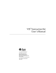
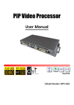
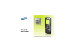
Kramer Electronics, Ltd.
USER MANUAL
Model:
VP-725DS
Presentation Switcher / Scaler
Introduction
Contents
1
Introduction
1
2
Getting Started
1
3
Overview
2
4
Your VP-725DS Presentation Switcher / Scaler
5
5.1
5.2
Connecting the VP-725DS Presentation Switcher / Scaler
Connecting a PC
Connecting the VP-725DS via the ETHERNET port
8
9
10
6
6.1
6.2
Understanding the Presentation Switcher / Scaler
Understanding the Video Group Mode/Scaler Mode
Understanding the PIP Button Feature
12
12
12
6.2.1
6.2.2
6.2.3
6.2.4
6.2.5
Activating the PIP Feature
PIP Characteristics
Toggling between the PIP and the Screen Source (SWAP)
Resizing the PIP
Moving the Position of the PIP
13
14
14
14
14
6.3
Locking and Unlocking the Front Panel
15
7
7.1
Operating the Presentation Switcher / Scaler
Switching an Input
16
16
7.1.1
7.1.2
Freezing the Image
Displaying a Blank Screen
16
17
7.2
Choosing the Output Resolution
18
8
8.1
Controlling the VP-725DS Presentation Switcher / Scaler
Operating via the OSD MENU Screen
19
19
8.1.1
8.1.2
8.1.3
8.1.4
Controlling the Brightness and Contrast
Controlling the Gamma and Color
Selecting the Source
Controlling the Geometry
20
20
21
24
8.1.4.1
8.1.4.2
Adjusting the Zoom Ratio
Adjusting the Zoom Position
26
27
8.1.5
Configuring via the Utility Screens
28
8.1.5.1
8.1.5.2
8.1.5.3
8.1.5.4
8.1.5.5
8.1.5.6
8.1.5.7
Choosing the Graphic Utility Settings
Choosing the Video Utility Settings
Choosing the PIP Utility Settings
Choosing the Seamless Switch Utility Settings
Choosing the OSD Utility Settings
Choosing the Output Utility Settings
Choosing Factory Reset
28
30
31
32
33
35
37
8.1.6
Verifying Configuration Details via the Information Screen
37
4
i
Introduction
8.2
8.3
8.4
Operating via the LCD Display
Operating via the Infra-red Remote Control Transmitter
Operating via ETHERNET
38
38
41
9
Technical Specifications
41
10
VP-725DS Communication Protocol
41
Figures
Figure 1: VP-725DS Presentation Switcher / Scaler
Figure 2: Connecting the PC
Figure 3: RJ-45 PINOUT
Figure 4: Connecting the VP-725DS Presentation Switcher / Scaler
Figure 5: OSD PIP Status
Figure 6: OSD SWAP Status
Figure 7: Locking / Unlocking the Front Panel
Figure 8: OSD Input Status
Figure 9: OSD Output Status
Figure 10: Controlling the Brightness and Contrast
Figure 11: Menu Screen Icons
Figure 12: Controlling the Gamma and Color
Figure 13: Gamma, Color Temperature/Manager User 1/2 Screen
Figure 14: Selecting the Source
Figure 15: Selecting the Search
Figure 16: Selecting the Group
Figure 17: Selecting the Source
Figure 18: Geometry Screen
Figure 19: Geometry (Aspect Ratio) Screen
Figure 20: Geometry (Zoom) Screen
Figure 21: OSD Enlarge Status
Figure 22: Zoom Ratio Adjustment Example
Figure 23: Zoom Position Adjustment Example
Figure 24: Geometry (Zoom Ratio) Screen
Figure 25: Geometry (Zoom Position Adjustment) Screen
Figure 26: Geometry (Keystone) Screen
Figure 27: Utility Screen
Figure 28: Choosing the Graphic Utility Settings
Figure 29: Graphic Setting Color Format Utility Screen
Figure 30: Choosing the Video Utility Settings
Figure 31: Video Setting Standard Utility Screen
Figure 32: Choosing the PIP Utility Settings
Figure 33: Choosing the Seamless Switch Utility Settings
Figure 34: Choosing the OSD Utility Settings
Figure 35: OSD Size Utility Screen
ii
5
9
10
11
13
14
15
16
18
19
20
20
21
21
23
23
23
24
25
25
26
26
26
27
27
28
28
29
29
30
30
31
32
33
33
KRAMER: SIMPLE CREATIVE TECHNOLOGY
Introduction
Figure 36: OSD Blank Color Utility Screen
Figure 37: Choosing the Output Utility Settings
Figure 38: Output Setting Resolution Utility Screen
Figure 39: Output Setting Refresh Rate Utility Screen
Figure 40: Output Setting User Mode Setting Utility Screen
Figure 41: Factory Reset Utility Screen
Figure 42: Information Screen
Figure 43: Example of how to use the LCD Display
Figure 44: Infra-red Remote Control Transmitter
34
35
36
36
36
37
37
38
39
Tables
Table 1: Front Panel VP-725DS Presentation Switcher / Scaler Features
Table 2: Rear Panel VP-725DS Presentation Switcher / Scaler Features
Table 3: Crossover Cable RJ-45 PINOUT
Table 4: Straight-through Cable RJ-45 PINOUT
Table 5: Controlling the Brightness and Contrast
Table 6: Controlling the Gamma and Color
Table 7: Selecting the Source
Table 8: Controlling the Geometry
Table 9: Choosing the Graphic Utility Settings
Table 10: Choosing the Video Utility Settings
Table 11: Choosing the PIP Utility Settings
Table 12: Choosing the Seamless Switch Utility Settings
Table 13: Choosing the OSD Utility Settings
Table 14: Choosing the Output Utility Settings
Table 15: User Mode Setting Definitions
Table 16: Infra-red Remote Control Transmitter Functions
Table 17: Technical Specifications of the VP-725DS Presentation Switcher / Scaler
6
7
10
10
20
21
22
24
29
30
31
32
33
35
37
40
41
iii
Introduction
1
Introduction
Welcome to Kramer Electronics (since 1981): a world of unique, creative and
affordable solutions to the infinite range of problems that confront the video,
audio and presentation professional on a daily basis. In recent years, we have
redesigned and upgraded most of our line, making the best even better! Our
300-plus different models now appear in 8 Groups1, which are clearly defined
by function.
Congratulations on purchasing your Kramer VP-725DS Presentation
Switcher, which is ideal for the following typical applications:
Projection systems in conference rooms, board rooms, auditoriums,
hotels, and churches
Any application in which high quality conversion and switching of
multiple and different video signals to graphical data is required for projection
and large display purposes
The package includes these items:
VP-725DS Presentation Switcher / Scaler
Power cord2
Infra-red remote control transmitter (including the required battery)
Null-modem adapter
This user manual3
2
Getting Started
We recommend that you:
Unpack the equipment carefully and save the original box and packaging
materials for possible future shipment
Review the contents of this user manual
Use Kramer high performance high resolution cables4
1 GROUP 1: Distribution Amplifiers; GROUP 2: Video and Audio Switchers, Matrix Switchers and Controllers; GROUP 3:
Video, Audio, VGA/XGA Processors; GROUP 4: Interfaces and Sync Processors; GROUP 5: Twisted Pair Interfaces;
GROUP 6: Accessories and Rack Adapters; GROUP 7: Scan Converters and Scalers; and GROUP 8: Cables and Connectors
2 We recommend that you use only the power cord that is supplied with the machine
3 Download up-to-date Kramer user manuals from the Internet at this URL: http://www.kramerelectronics.com/manuals.html
4 The complete list of Kramer cables is on our Web site at http://www.kramerelectronics.com (click “Cables and Connectors”
in the Products section)
1
Overview
3
Overview
The VP-725DS Presentation Switcher / Scaler is designed for a wide variety
of presentation and multimedia applications. It is a true multi-standard video
to graphics scaler and presentation switcher for a wide variety of presentation
and multimedia applications. It consists of a very high quality scaler with many
user-selectable pixel-rates including VGA (640x480), SVGA (800x600), XGA
(1024x768), SXGA (1280x1024) and UXGA (1600x1200); high definition
television HDTV (480p, 720p and 1080i); and several optimum plasma and
LCD rates such as 852x1024i, 1024x1024i, 1366x768, 1365x1024, 1280x720,
720x483, 852x480, 1400x1050, 576P, 720x400, 832x624, 1024x800,
1152x864, 1152x870, 1152x900, 1280x960, 1280x768, 1024x576, as well as
a user definable output mode1.
In particular, the VP-725DS:
Offers high quality de-interlacing 3:2/2:2 pull down2
Supports firmware upgrade via RS-232
Includes non-volatile memory that retains the last setting, after switching
the power off and then on again
Scales and zooms (to up to 400% of the original size)
Digitally reprocesses the signal to correct mastering errors, and
regenerates the video at a chosen line and pixel rate format, providing, for
example, native-resolution video for LCD, DLP and Plasma displays
Facilitates scaling of graphics resolutions to other resolutions
Incorporates a unique graphics-scaling engine with image enhancement
algorithms, which are built into the firmware
Is specifically designed to improve video quality by reducing chroma noise
Includes an OSD (on-screen display) for making the adjustments that can
be located anywhere on the screen, and can be doubled in size. The OSD can
be used to deactivate the source prompt, choose the color of the blank screen,
and choose from three seamless switching transition speeds
Consists of 5 video groups—composite video, s-Video, component video
(RGB or YPbPr), DVI-D and VGA—and each group has 4 inputs (except for
DVI which has 2 inputs)
1 Recommended for advanced users only – non-standard settings may not be recognized by the display device
2 Accommodates the frame-rate of a converted movie (24 frames per second) to video frequencies (25 frames per second
(PAL); 30 frames per second (NTSC)
2
KRAMER: SIMPLE CREATIVE TECHNOLOGY
Overview
Has multi-standard video support; supports VESA standards; HDTV
standards and other popular resolutions on the input. Does not support1 HDCP
(High bandwidth Digital Content Protection) on the DVI2
Features two modes of operation: Video Group Mode and Scaler Mode.
These modes function simultaneously and independently (except for DVI:
once a DVI input is selected in the Scaler Mode, that DVI input selection
cannot be changed in the Video Group Mode)
Video Group Mode selects the input from each group: CV, YC,
Component, VGA, DVI for switching to its local (group) output
Scaler Mode converts the selected input (one of 18) to the SCALED
OUTPUTS
Includes a front panel lock, as well as a separate OSD lock
In addition to providing an up- or down- scaled output of the selected (one
of 18) inputs, also functions as 4x1 switchers for each video group (2x1 for DVI)
Has ProcAmp3 controls for the scaler output
Lets you freeze the image at any instant
Lets you select the output colorspace (RGB or YPbPr)
Has a text overlay feature4 for easy insertion of subtitles, karaoke script,
text banners, and the like
Includes a built-in Picture-In-Picture (PIP) inserter5 (letting you insert a
video source into a graphics background or vice versa. This PIP image may be
positioned and sized anywhere on the screen, or displayed as 2 images
side-by-side (Split-Screen)
The VP-725DS:
Comes in a rugged, professional 19" 3U rack-mountable metal enclosure
Uses a universal 100-240VAC automatic power supply
1 A method of security encryption (developed by Intel and Silicon Image)
2 An HDCP source would show up as a very snowy, noisy picture at the output
3 Processing amplification enables adjustment of different video and audio signal parameters
4 The Text Overlay Application Program is included on the CD / is available for download at this URL:
http://www.kramerelectronics.com/searchdx.html. This user-friendly program may be used to generate and send text to be
displayed on the scaled output
5 See section 6.1
3
Your VP-725DS Presentation Switcher / Scaler
Control the VP-725DS:
From the front panel user-friendly menu-driven OSD (see section 8.1)
From the front panel high contrast LCD Display (see section 8.2)
Remotely, from the infra-red remote control transmitter (see section 8.3)
Via Ethernet (see section 8.4)
Remotely, via RS-232
Achieving the best performance means:
Connecting only good quality connection cables, thus avoiding
interference, deterioration in signal quality due to poor matching, and elevated
noise levels (often associated with low quality cables)
Avoiding interference from neighboring electrical appliances and
positioning your VP-725DS away from moisture, excessive sunlight and dust
4
Your VP-725DS Presentation Switcher / Scaler
Figure 1, Table 1 and Table 2 define the VP-725DS:
4
KRAMER: SIMPLE CREATIVE TECHNOLOGY
Your VP-725DS Presentation Switcher / Scaler
Figure 1: VP-725DS Presentation Switcher / Scaler
5
Your VP-725DS Presentation Switcher / Scaler
Table 1: Front Panel VP-725DS Presentation Switcher / Scaler Features
INPUT
SELECTOR
#
1
2
3
Feature
VGA Button
DVI Button
Function
Selects one of the 4 VGA sources
Selects one of the 2 DVI sources1
CV Button
Selects one of the 4 CV sources
4
5
6
7
YC Button
COMP Button
POWER Switch
IR Receiver / LED
8
9
FREEZE Button
PIP Button
10 MENU Button
Selects one of the 4 s-Video (Y/C) sources
Selects one of the 4 Component sources
Illuminated switch for turning the unit ON or OFF
Green when the unit will accept IR remote commands; red in
2
standby mode
Freezes the output video image3
3,4
Selects the picture-in-picture function
11 ENTER Button
Displays the OSD Menu screen (or moves to the previous level in
3,5
the OSD screen) and locks/unlocks the front panel
3
Moves to the next level in the OSD screen
12 - Button
13 + Button
Decreases the range by one step3
Increases the range by one step3
14 DOWN Button
15 UP Button
Moves down one step (in the same level) in the OSD screen
3
Moves up one step (in the same level) in the OSD screen
16 OSD ON Button
17 LCD STATUS Display
Activates/deactivates access to the OSD Menu3, 6
Displays the status
19
SCALER Button
MODE
SELECT
18
3
When selected shows which of the 18 video inputs has been
selected to be scaled at the SCALED OUTPUTS, and facilitates
the selection of an alternative video input for scaling
VIDEO GROUP Button Shows which video input from each group is selected for
switching, and facilitates the selection of an alternative video input
from each group1
1 Note, that once a DVI input is selected in the Scaler Mode, that DVI input selection cannot be changed in the Video Group
Mode
2 After pressing the POWER key on the remote control transmitter (see Figure 44). The machine is temporarily powered
down except that the power switch (item 6) on the machine continues to illuminate
3 Scaler outputs only
4 See section 6.1
5 See section 6.3
6 The OSD ON front panel button is activated (illuminated) by default, and pressing the MENU front panel button (or the
MENU key on the infra-red remote control transmitter (see Figure 44)) displays the OSD Menu. To block display of the OSD
Menu, press the OSD ON front panel button (or the OSD key) to deselect the OSD ON front panel button (which is no longer
illuminated); the OSD OFF status appears superimposed over the top right corner of the screen. However, deselecting the
OSD ON front panel button during an OSD operation will not turn off the OSD Menu (even though the OSD OFF status
appears superimposed over the top right corner of the screen), letting you complete the OSD operation
6
KRAMER: SIMPLE CREATIVE TECHNOLOGY
Your VP-725DS Presentation Switcher / Scaler
#
1
2
3
4
5
6
COMP
COMP
INPUTS OUTPUT
Table 2: Rear Panel VP-725DS Presentation Switcher / Scaler Features
Feature
R/Pr BNC Connector
B/Pb BNC Connector
Function
Connect to the component video acceptor or to an RGB acceptor
G/Y BNC Connector
R/Pr BNC Connector
B/Pb BNC Connector
Connect to the component video source or RGB source from 1 to 4
G/Y BNC Connector
ETHERNET port
8
CV OUT BNC Connector
Connects to the composite video acceptor
9
CV IN BNC Connectors
Connects to the composite video sources from 1 to 4
10 VGA IN HD15 Connectors
Connects to your LAN
1
7
Connects to the VGA (analog interface) graphics sources from 1 to 4
Connects to the VGA (analog interface) graphics acceptor
12 YC IN 4p Connectors
Connects to the s-Video (Y/C) sources from 1 to 4
13 YC OUT 4p Connector
Connects to the s-Video (Y/C) acceptor
14 DVI IN Connectors
Connects to the DVI (digital video interface) graphics sources from 1
to 2
15 DVI OUT Connector
16
H BNC Connector
Connects to the DVI (digital video interface) graphics acceptor
17
18
19
20
21
22
SCALED OUPUTS
11 VGA OUT HD15 Connector
R/Pr BNC Connector
V BNC Connector
Connects to the component video or RGB acceptor
G/Y BNC Connector
B/Pb BNC Connector
DVI Connector
Connects to the DVI (digital video interface) graphics acceptor
VGA HD15 Connector
Connects to the VGA (analog interface) graphics acceptor
23 RS-232 DB 9 Connector
Connects to PC or Serial Controller
24 Power Connector with FUSE
AC connector enabling power supply to the unit
1 Local Area Network (that is, computers sharing a common communications line or wireless link, which often share a server
within a defined geographic area)
7
Connecting the VP-725DS Presentation Switcher / Scaler
5
Connecting the VP-725DS Presentation Switcher / Scaler
This section describes how to connect the VP-725DS. In particular, how to:
Connect the VP-725DS rear panel (see this section)
Connect the PC (see section 5.1)
Connect the ETHERNET port (see section 5.2)
Using the VP-725DS you can select any one of the 18 inputs and scale that
input to up to three scaled outputs (at the identical resolution).
To connect the VP-725DS, connect the following1 to the rear panel, as the
example in Figure 4 illustrates:
1. Connect one or more of the following video sources:
Up to 4 VGA graphics sources (for example, computers): VGA Source 1,
VGA Source 2, VGA Source 3 and VGA Source 4 to the HD15 input connectors
Up to 4 composite video sources2: CV Source 1, CV Source 2, CV Source
3, and CV Source 4 to the BNC input connectors
Up to 4 s-Video sources2: YC Source 1, YC Source 2, YC Source 3, and
YC Source 4 to the 4p input connectors
Up to 4 component video (sometimes called YUV, or Y, B-Y, R-Y, or Y,
Pb/Cb, and Pr/Cr ) sources or 4 RGB sources3: COMP Source 1, COMP
Source 2, COMP Source 3, and COMP Source 4 to the 4 sets of 3 BNC
connectors, G/Y, B/Pb, and R/Pr
Up to 2 DVI4 graphics sources (for example, computers): DVI Source 1
and DVI Source 2 to the DVI connectors
2. Connect the CV OUT BNC connector, the YC OUT 4p connector, and
the VGA OUT HD15 connector to the respective video inputs on the
projector.
3. Connect the COMP OUTPUT BNC connectors: G/Y, B/Pb, and R/Pr to
the respective component video inputs on the Plasma monitor.
4. Connect up to 3 SCALED OUTPUTS, as follows:
Connect the RGBHV connectors (G/Y, B/Pb, R/Pr, H, and V) to the
1 Switch OFF the power on each device before connecting it to your VP-725DS. After connecting your VP-725DS, switch on
its power and then switch on the power on each device
2 For example, VCR machines
3 For example, an HDTV satellite receiver to COMP Source 1, and a Betacam VCR machine (or an RGB camera) to COMP
Source 4
4 Not HDCP sources
8
KRAMER: SIMPLE CREATIVE TECHNOLOGY
Connecting the VP-725DS Presentation Switcher / Scaler
RGBHV acceptor, for example, a Plasma monitor
Connect the DVI connector to the DVI acceptor, for example, a projector.
Connect the VGA connector to the VGA acceptor, for example, a monitor.
5. Connect the power cord1 (not illustrated in Figure 4).
6. Connect a PC (optional), see section 5.1.
7. Connect the ETHERNET port (optional), see section 5.2.
5.1 Connecting a PC
You can connect a PC (or other controller) to the VP-725DS via the RS-232
port for remote control, and for upgrading the firmware.
To connect a PC to a VP-725DS unit, using the Null-modem adapter
provided with the machine (recommended):
Connect the RS-232 DB9 rear panel port on the VP-725DS unit to the
Null-modem adapter and connect the Null-modem adapter with a 9 wire flat
cable to the RS-232 DB9 port on your PC
To connect a PC to a VP-725DS unit, without using a Null-modem adapter:
Connect the RS-232 DB9 port on your PC to the RS-232 DB9 rear panel
port on the VP-725DS unit, forming a cross-connection2, as Figure 2 illustrates
DB9 (FromPC)
DB9 (To Presentation
Switcher / Scaler)
Figure 2: Connecting the PC
1 We recommend that you use only the power cord that is supplied with this machine
2 Also known as a Null-modem connection
9
Connecting the VP-725DS Presentation Switcher / Scaler
5.2 Connecting the VP-725DS via the ETHERNET port
To connect the VP-725DS via the ETHERNET port, do the following:
Connect the ETHERNET port of the VP-725DS to the LAN port of your
PC, via a crossover cable with RJ-45 connectors, as Table 3 and Figure 3 define
Figure 3: RJ-45 PINOUT
Table 3: Crossover Cable RJ-45 PINOUT
EIA /TIA 568A
Side 2
PIN
1
2
3
4
5
6
7
8
EIA /TIA 568B
Side 1
Wire Color
Green / White
Green
Orange / White
Blue
Blue / White
Orange
Brown / White
Brown
PIN
1
2
3
4
5
6
7
8
Wire Color
Orange / White
Orange
Green / White
Blue
Blue / White
Green
Brown / White
Brown
Pair 1
4 and 5
Pair 1
Pair 2
3 and 6
Pair 2
4 and 5
1 and 2
Pair 3
Pair 4
1 and 2
7 and 8
Pair 3
Pair 4
3 and 6
7 and 8
If connecting the ETHERNET port of the VP-725DS to the LAN port on
a network hub or network router, use a straight-through cable with RJ-45
connectors, as Table 4 defines
Table 4: Straight-through Cable RJ-45 PINOUT
EIA /TIA 568A
Side 2
PIN
1
2
3
4
5
6
7
8
10
Wire Color
Orange / White
Orange
Green / White
Blue
Blue / White
Green
Brown / White
Brown
EIA /TIA 568B
Side 1
PIN
1
2
3
4
5
6
7
8
Wire Color
Orange / White
Orange
Green / White
Blue
Blue / White
Green
Brown / White
Brown
KRAMER: SIMPLE CREATIVE TECHNOLOGY
Connecting the VP-725DS Presentation Switcher / Scaler
Figure 4: Connecting the VP-725DS Presentation Switcher / Scaler
11
Understanding the Presentation Switcher / Scaler
6
Understanding the Presentation Switcher / Scaler
The VP-725DS includes the following front panel buttons:
A set of 18 INPUT SELECTOR buttons
A set of 2 MODE SELECT buttons1
A FREEZE button (see section 7.1.1)
A PIP button (see section 6.1)
A set of 7 OSD buttons (described in Table 1): OSD ON, MENU, ENTER,
-, +, UP, and DOWN
6.1 Understanding the Video Group Mode/Scaler Mode
This is a machine with an 18x1:3 switcher for the Scaler, as well as individual
video switchers for the 5 Video Groups: composite video, s-Video,
component video (RGB or YPbPr), DVI-D and VGA.
When the VP-725DS is in use, both modes operate simultaneously, as well as
independently. That is, the Scaler output is available even when switching in
the Video Group mode, and visa-versa (except for DVI: once a DVI input is
selected in the Scaler Mode, that DVI input selection cannot be changed in
the Video Group Mode).
6.2 Understanding the PIP Button Feature
The Picture-in-Picture inserter (PIP) is used for the simultaneous display of
video and graphic sources, and lets you display:
An inserted video source2 PIP over a graphic source3
An inserted graphic source3 PIP over a video source2
Your Presentation Switcher / Scaler automatically recognizes and displays
only the relevant sources, as the following 2 examples illustrate:
Choosing the AV 1 PIP source when the VGA input is selected, will
insert the composite video source over the VGA graphic displayed on the
screen. You can choose a component4, YC 1, YC 2 or AV 2 PIP source5
1 VIDEO GROUP MODE SELECT: selects the video input from each group for switching, and SCALER MODE SELECT:
converts the selected video input (one of 18) at each of the SCALED OUTPUTS
2 That is, composite, s-Video or component
3 That is, DVI, VGA or component
4 At video frequencies
5 As long as it is connected and switched on. Otherwise, choosing it will display a blank screen
12
KRAMER: SIMPLE CREATIVE TECHNOLOGY
Understanding the Presentation Switcher / Scaler
(instead of the AV 1). You cannot choose VGA 1, VGA 2 or DVI1
Choosing the VGA 1 PIP source when the AV 1 input is selected, will
insert the VGA graphic source over the composite video displayed on the
screen. You can choose a component2, VGA 2 or DVI PIP source3 (instead of
the VGA 1). You cannot choose AV 2, YC 1, or YC 2
6.2.1
Activating the PIP Feature
To activate the PIP (which illuminates the PIP button), do one of the
following:
Press the PIP button
Switch on the PIP functionality via the OSD Menu
Press the PIP key on the remote control transmitter (see Figure 44)
When the Source Prompt is ON, the PIP is enclosed by an orange frame, and
the OSD PIP status appears superimposed over the top right corner of the
screen for a few seconds, as Figure 5 illustrates. After a few seconds4, the
orange frame and the OSD PIP status automatically disappear5.
Activating the PIP subsequently cycles between the PIP with the orange
frame and no PIP.
Figure 5: OSD PIP Status
When the Source Prompt is OFF, activating the PIP toggles between the PIP
(with no frame and no OSD PIP status) and no PIP.
1 As these are graphics sources and you cannot insert a graphics PIP over a graphics source
2 At graphic frequencies
3 As long as it is connected and switched on. Otherwise, choosing it will display a blank screen
4 By default, 20 seconds. But you can reset the timeout (from 3 to 60 seconds), see section 8.1.5.5
5 Trying to activate the PIP again while the PIP is still enclosed by an orange frame deactivates the PIP
13
Understanding the Presentation Switcher / Scaler
6.2.2
PIP Characteristics
You can determine the following PIP characteristics:
PIP Source
PIP Size (1/25, 1/16, 1/9, 1/4, or split screen)
Horizontal and Vertical position, placing it anywhere on the screen
6.2.3
Toggling between the PIP and the Screen Source (SWAP)
To toggle back and forth between the PIP content and the screen source
content, do the following:
Press the SWAP key on the Infra-red remote control transmitter (see Figure 44)
The OSD SWAP status appears superimposed over the top right corner of the
screen for a few seconds1, as Figure 6 illustrates
Figure 6: OSD SWAP Status
6.2.4
Resizing the PIP
To resize the PIP (1/25, 1/16, 1/9, 1/4, or split screen):
When the Source Prompt is ON and the PIP is enclosed by an orange
frame, use the Up and/or Down navigation control keys on the infra-red
remote control transmitter (see Figure 44) or the UP and/or DOWN front panel
OSD buttons
Use the OSD Menu
6.2.5
Moving the Position of the PIP
To move the location of the PIP:
When the Source Prompt is OFF (or ON, but without the orange frame),
use the four navigation control keys on the infra-red remote control transmitter
(see Figure 44), or the UP, DOWN, + and/or – front panel OSD buttons
1 By default, 20 seconds. But you can reset the timeout (from 3 to 60 seconds), see section 8.1.5.5
14
KRAMER: SIMPLE CREATIVE TECHNOLOGY
Understanding the Presentation Switcher / Scaler
6.3 Locking and Unlocking the Front Panel
To prevent accidental changes to settings or unauthorized tampering with the
front panel, you can lock the front panel. This disengages the front panel
switches except for the MENU button on the front panel (press and hold for 3
seconds to unlock). When the front panel is locked, control from the infra-red
remote transmitter is also blocked1.
To lock the front panel:
Press and hold the MENU front panel OSD button or the MENU key on
the infra-red remote control transmitter (see Figure 44) for a few seconds, until
the Key Lock On OSD status appears superimposed over the top right corner
of the screen (when the Source Prompt is ON) for a few seconds2, as Figure 7
illustrates
Figure 7: Locking / Unlocking the Front Panel
To unlock the front panel (releasing the protection mechanism):
Press and hold the MENU front panel OSD button or the MENU key on
the infra-red remote control transmitter (see Figure 44) for a few seconds, until
the Key Lock Off OSD status appears superimposed over the top right corner
of the screen (when the Source Prompt is ON) for a few seconds2
1 However, operation via RS-232 serial commands (remote controller or PC) and/or ETHERNET is still available
2 By default, 20 seconds. But you can reset the timeout (from 3 to 60 seconds), see section 8.1.5.5
15
Operating the Presentation Switcher / Scaler
7
Operating the Presentation Switcher / Scaler
This section describes how to:
Switch and scale an input (see section 7.1)
Select the output resolution (see section 7.2)
7.1 Switching an Input
You can switch seamlessly1 between each input2 that is connected to a source,
by pressing the appropriate INPUT SELECTOR button (when the SCALER
button is selected). The OSD status appears superimposed over the top right
corner of the screen (when the Source Prompt is ON) for a few seconds3, as
Figure 8 illustrates:
Figure 8: OSD Input Status
You can also use the INPUT SELECTOR button to freeze the image (see
section 7.1.1) or to display a blank screen (see section 7.1.2).
7.1.1
Freezing the Image
You can freeze the image, by either:
Pressing the FREEZE key on the infra-red remote control transmitter (see
Figure 44) or the FREEZE front panel button
The image freezes. The FREEZE front panel button illuminates and the
appropriate INPUT SELECTOR button flashes. The Freeze OSD status appears
superimposed over the top right corner of the screen (when the Source Prompt
is ON) for a few seconds3; or
1 For glitchless transitions between inputs
2 To set the image transition speed (fast, moderate or safe), see section 8.1.5.4
3 By default, 20 seconds. But you can reset the timeout (from 3 to 60 seconds), see section 8.1.5.5
16
KRAMER: SIMPLE CREATIVE TECHNOLOGY
Operating the Presentation Switcher / Scaler
Pressing the appropriate illuminated INPUT SELECTOR front panel
button or the appropriate INPUT SELECTOR key on the infra-red remote
control transmitter (see Figure 44)
The image freezes. The FREEZE front panel button illuminates and the
appropriate INPUT SELECTOR button flashes. The Freeze OSD status
appears superimposed over the top right corner of the screen (when the Source
Prompt is ON) for a few seconds1
7.1.2
Displaying a Blank Screen
You can display a blank screen, as follows:
1. Press the appropriate illuminated INPUT SELECTOR front panel button
or the appropriate INPUT SELECTOR key on the infra-red remote
control transmitter (see Figure 44)2.
The image freezes. The FREEZE front panel button illuminates and the
appropriate INPUT SELECTOR button flashes. The Freeze OSD status
appears superimposed over the top right corner of the screen (when the
Source Prompt is ON) for a few seconds1
2. Press the appropriate flashing INPUT SELECTOR front panel button or
the INPUT SELECTOR key on the infra-red remote control transmitter
(see Figure 44)
The frozen image is replaced by a blank screen. The FREEZE front panel
button continues to illuminate and the appropriate INPUT SELECTOR
button flashes more slowly. The Blank status appears superimposed over
the top right corner of the screen (when the Source Prompt is ON) for a
few seconds1
You can choose the color of the blank screen (blue or black - see Figure 36).
1 By default, 20 seconds. But you can reset the timeout (from 3 to 60 seconds), see section 8.1.5.5
2 Alternatively, press the FREEZE key on the infra-red remote control transmitter (see Figure 44) or the FREEZE front panel
button. This will cause the FREEZE front panel button to illuminate and the appropriate INPUT SELECTOR button to flash
17
Operating the Presentation Switcher / Scaler
7.2 Choosing the Output Resolution
You can select the output resolution by pressing the OUT key on the infra-red
remote control transmitter (see Figure 44) or via the Output Setting OSD
menu (see Table 14). The OSD status appears superimposed over the top right
corner of the screen (when the Source Prompt is ON) for a few seconds1, as
Figure 9 illustrates2:
Figure 9: OSD Output Status
1 By default, 20 seconds. But you can reset the timeout (from 3 to 60 seconds), see see section 8.1.5.5
2 Adjusting the output resolution results in a corresponding adjustment to the size of the OSD status window
18
KRAMER: SIMPLE CREATIVE TECHNOLOGY
Controlling the VP-725DS Presentation Switcher / Scaler
8
Controlling the VP-725DS Presentation Switcher / Scaler
You can control the Presentation Switcher / Scaler via:
The OSD Menu Screen (see section 8.1)
The front panel LCD Display (see section 8.2)
The infra-red remote control transmitter (see section 8.3)
ETHERNET (see section 8.4)
RS-232 remote control
8.1 Operating via the OSD MENU Screen
The OSD superimposes a menu on the screen from which you can control
your VP-725DS. When the OSD ON front panel button is selected, pressing
the MENU front panel OSD button or the MENU key on the infra-red remote
control transmitter (see Figure 44) displays the first OSD screen, the
“Brightness and Contrast” screen (see Figure 10).
If the OSD is locked1, pressing the MENU front panel OSD button or the
MENU key on the infra-red remote control transmitter (see Figure 44) will
not display the “Menu screen”. In this case, you can navigate via the front
panel LCD.
After initially pressing the MENU front panel OSD button or the MENU key
on the infra-red remote control transmitter, each subsequent press moves to
the previous level in the OSD screen (Esc.).
Figure 10: Controlling the Brightness and Contrast
1 Pressing the OSD ON front panel OSD button or the OSD key on the infra-red remote control transmitter (see Figure 44)
will block access to the OSD Menu
19
Controlling the VP-725DS Presentation Switcher / Scaler
Figure 11 defines the six interactive icons1:
Brightness
and
Contrast
Gamma
and Color
Source
Geometry
Utility
Information
Figure 11: Menu Screen Icons
8.1.1
Controlling the Brightness and Contrast
Figure 10 and Table 5 define the Brightness and Contrast Screen:
Table 5: Controlling the Brightness and Contrast
Brightness and Contrast
Level 1
Range
Brightness 0 to 128
Contrast
0 to 128
8.1.2
Default
64
64
Controlling the Gamma and Color
Figure 12 and Table 6 define the Gamma and Color Screen. You can choose
Normal (average setting), Presentation (higher black level), Cinema (higher
white balance), Nature (higher green level), User 1 or User 2.
Figure 12: Controlling the Gamma and Color
1 Each icon represents a Level 1 function. In addition to Level 1, the OSD structure includes Level 2 (a subset of level 1),
Level 3 (a subset of level 2), Level 4 (a subset of level 3) and Range
20
KRAMER: SIMPLE CREATIVE TECHNOLOGY
Controlling the VP-725DS Presentation Switcher / Scaler
Table 6: Controlling the Gamma and Color
Gamma and Color
Level 1
Normal
Presentation
Cinema
Nature
User 1 / 2
Level 2
Range
Gamma
-10 to 10
Color Temperature
Red
0 to 127
Green
0 to 127
Blue
0 to 127
Color Manager
Red
0 to 32
Green
0 to 32
Blue
0 to 32
Yellow
0 to 32
Default
0
64
64
64
16
16
16
16
Choosing User 1 or User 2 from the Gamma and Color Screen illustrated in
Figure 12, displays the Gamma, Color Temperature and Color Manager
Screen in Figure 13. Each user setting is customized to the applicable
environment. The user sets the parameters and saves them for recall later.
Figure 13: Gamma, Color Temperature/Manager User 1/2 Screen
8.1.3
Selecting the Source
Figure 14 and Table 7 define the Source (Search, Select, and Source) Screen.
Figure 14: Selecting the Source
21
Controlling the VP-725DS Presentation Switcher / Scaler
Table 7: Selecting the Source
Source
Level 1
Level 2
Level 3
Search Manual
Auto
Select
Video Group
1
Audio Group
AV Group1
Scaler
Master Audio1
1
Master AV
Source VGA Group
VGA1
VGA2
VGA3
VGA4
DVI Group
DVI1
DVI2
Comp Group Comp1
Comp2
Comp3
Comp4
YC Group
YC1
YC2
YC3
YC4
AV Group
AV1
AV2
AV3
AV4
Master
VGA1
VGA2
VGA3
VGA4
DVI1
DVI2
Comp1
Comp2
Comp3
Comp4
YC1
YC2
YC3
YC4
AV1
AV2
AV3
AV4
Figure 15 illustrates the Search (Manual or Auto) option:
1 Disabled on the VP-725DS; available on the VP-725DSA
22
KRAMER: SIMPLE CREATIVE TECHNOLOGY
Controlling the VP-725DS Presentation Switcher / Scaler
Figure 15: Selecting the Search
Selecting Manual Search disables the Auto Search option (which finds the
active source). After powering up, the VP-725DS will not scan for an active
input but will display the source selected prior to power down, even if that
input is inactive. Figure 16 illustrates the Group Select option. The Video
Group and Scaler are available1 with the VP-725DS:
Figure 16: Selecting the Group
Figure 17 illustrates the Source:
Figure 17: Selecting the Source
1 The Audio Group, AV Group, Master Audio, and Master AV are available with the VP-725DSA
23
Controlling the VP-725DS Presentation Switcher / Scaler
8.1.4
Controlling the Geometry
Figure 18 and Table 8 define the main Geometry Screen, from which you can
choose the aspect ratio, zoom, and set the keystone angle:
Figure 18: Geometry Screen
Table 8: Controlling the Geometry
Geometry
Level 1
Aspect Ratio
Level 2
Anamorphic
Virtual Wide
Letterbox
Native
4:3 Output
User Define
24
Zoom
Zoom Ratio
Keystone
Zoom Position Adjustment
Angle
Level 3
Range
Default
Pan
Left + Up
Right + Up
Center
Left + Down
Right +
Down
Shift
H-Zoom
V-Zoom
H-Pan
H- Pan
100%
150%
200%
225%
250%
275%
300%
325%
350%
375%
400%
-32 to 32
0
-32 to 32
-32 to 32
-32 to 32
-32 to 32
-32 to 32
0
0
0
0
0
-32 to 32
0
KRAMER: SIMPLE CREATIVE TECHNOLOGY
Controlling the VP-725DS Presentation Switcher / Scaler
Figure 19 illustrates the Geometry (Aspect Ratio) Screen. You can set the
following characteristics according to your specific requirements: anamorphic
(displays the aspect ratio (usually 16:9)), virtual wide (anamorphic plus
non-linear scaling), letterbox (the vertical line is expanded to full screen1— it
is assumed that there are two bands of black, top and bottom of the screen),
native (lets you set the native resolution according to the specifications of the
plasma screen or projector), 4:3 output (the length to height ratio is 4:3), and
user define (H-Zoom, V-Zoom, H-Pan, and V-Pan):
Figure 19: Geometry (Aspect Ratio) Screen
Figure 20 illustrates the Geometry (Zoom) Screen:
Figure 20: Geometry (Zoom) Screen
The zoom ratio and the zoom position are illustrated by a small rectangle
inside a transparent pop-up OSD Enlarge status box that appears at the top
right corner of the screen, as the example in Figure 21 illustrates:
1 Panning the picture refers to resizing and cropping it
25
Controlling the VP-725DS Presentation Switcher / Scaler
Figure 21: OSD Enlarge Status
When you change the zoom ratio or zoom position, the screen image is
adjusted correspondingly, and the change is reflected in the pop-up OSD
Enlarge status box. For example, Figure 22 illustrates a zoom ratio increase
from 200% (Image A) to 400% (Image B):
Figure 22: Zoom Ratio Adjustment Example
Figure 23 illustrates how the pop-up OSD Enlarge status box shows a zoom
position adjustment from the top left corner (Image C) to the lower right
corner (Image D):
Figure 23: Zoom Position Adjustment Example
8.1.4.1
Adjusting the Zoom Ratio
You can adjust the zoom ratio to up to 400% via one or both of these methods:
Using the Zoom + and/or the Zoom - control keys1 on the infra-red
remote control transmitter (see Figure 44). The pop-up OSD Enlarge status
box continuously displays the zoom ratio and position, as Figure 21 illustrates
Using the OSD Menu buttons, as Figure 24 illustrates
1 The
26
and the
buttons
KRAMER: SIMPLE CREATIVE TECHNOLOGY
Controlling the VP-725DS Presentation Switcher / Scaler
Figure 24: Geometry (Zoom Ratio) Screen
8.1.4.2
Adjusting the Zoom Position
You can adjust the zoom position (see the example in Figure 23) via one or
more of the following methods:
Using the navigation control keys on the infra-red remote control
transmitter (see Figure 44), to fine tune the zoom position (that is, to slowly
zoom-in at any location on the screen)1
Using the OSD Menu buttons (see Figure 25)2
Figure 25: Geometry (Zoom Position Adjustment) Screen
You can adjust the Keystone (to keep the picture rectangular) according to
your specific requirements (see Figure 26).
1 For example, to zoom-in toward the lower right of the image, press the
and the
buttons separately, as required
2 For example, to zoom-in to the lower right part of the image instead of the top left part, press the + and DOWN OSD Menu
buttons separately, as required
27
Controlling the VP-725DS Presentation Switcher / Scaler
Figure 26: Geometry (Keystone) Screen
8.1.5
Configuring via the Utility Screens
You can determine how your VP-725DS will function either generally or on a
specific occasion, via the Utility screen settings (see Figure 27):
Figure 27: Utility Screen
8.1.5.1
Choosing the Graphic Utility Settings
Figure 28 and Table 9 define the Graphic1 Setting Utility screen. You can set
the color format (see Figure 29), position, color, hue, sharpness, frequency
and phase, as well as auto image2 and auto gain3.
1 When a VGA source is selected, “Graphic Setting” will be shown. “HDTV Setting” will appear when an HDTV source is
selected
2 Assesses the image and improves the quality accordingly, by automatically adjusting the phase, frequency and position
3 Automatically adjusts the brightness and contrast
28
KRAMER: SIMPLE CREATIVE TECHNOLOGY
Controlling the VP-725DS Presentation Switcher / Scaler
Figure 28: Choosing the Graphic Utility Settings
Table 9: Choosing the Graphic Utility Settings
Utility
Level 1
Graphic Setting
Level 2
Color Format
H-Position
V-Position
Color
Hue
Sharpness
Frequency
Phase
Auto Image
Auto Gain
Level 3
Default
RGB
YUV
Range
0 to 255
0 to 255
0 to 128
0 to 128
0 to 16
0 to 100
0 to 31
Default
128
128
70
64
8
49
0
Selecting the color format (see Figure 29) lets you select RGB or YUV1
colorspace. When the Default setting is chosen, the colorspace is set
according to the detected input resolution.
Figure 29: Graphic Setting Color Format Utility Screen
1 That is Y, B-Y, R-Y colorspace, also known as Y, Cb, Cr or Y, Pb, Pr
29
Controlling the VP-725DS Presentation Switcher / Scaler
8.1.5.2
Choosing the Video Utility Settings
Figure 30 and Table 10 define the Video Setting Utility screen. You can set the
Color Format, Standard (see Figure 31), color, hue, sharpness, and position.
Figure 30: Choosing the Video Utility Settings
Figure 31: Video Setting Standard Utility Screen
Table 10: Choosing the Video Utility Settings
Utility
Level 1
Level 2
Video Setting Color Format
Standard
Color
Hue
Sharpness
H-Position
V-Position
30
Level 3
Default
RGB
YUV
Auto
Level 4
Range
Default
Auto
NTSC
NTSC4.43
PAL
PAL-N
PAL-M
SECAM
0 to 128
0 to 128
0 to 16
0 to 20
0 to 20
64
64
11
15
10
KRAMER: SIMPLE CREATIVE TECHNOLOGY
Controlling the VP-725DS Presentation Switcher / Scaler
8.1.5.3
Choosing the PIP Utility Settings
Figure 32 and Table 11 define the PIP Setting Utility screen. You can activate
the PIP, choose the source, the size, and the position of the PIP.
Figure 32: Choosing the PIP Utility Settings
Table 11: Choosing the PIP Utility Settings
Utility
Level 1
PIP Setting
Level 2
PIP On/Off
Level 3 Range Default
Off
On
PIP Source VGA-1
VGA-2
VGA-3
VGA-4
DVI-1
DVI-2
Comp1
Comp2
Comp3
Comp4
YC-1
YC-2
YC-3
YC-4
AV-1
AV-2
AV-3
AV-4
PIP Size
1/25
1/16
1/9
1/4
Split
H-Position
0 to 36 1
V-Position
0 to 36 1
31
Controlling the VP-725DS Presentation Switcher / Scaler
8.1.5.4
Choosing the Seamless Switch Utility Settings
Figure 33 and Table 12 define the Seamless Switch Utility screen. You can
choose the image transition speed Mode1.
Figure 33: Choosing the Seamless Switch Utility Settings
Table 12: Choosing the Seamless Switch Utility Settings
Utility
Level 1
Seamless Switch
Level 2
Fast
Moderate
Safe
Default
*
1 FAST (an immediate switch, without checking the resolution. However, the image transition may appear unstable),
MODERATE (between fast and safe) or SAFE (a smooth image transition - the input resolution at the input is checked and
outputted after a few seconds delay, but it takes longer than fast)
32
KRAMER: SIMPLE CREATIVE TECHNOLOGY
Controlling the VP-725DS Presentation Switcher / Scaler
8.1.5.5
Choosing the OSD Utility Settings
Figure 34 and Table 13 define the OSD Setting Utility screen. You can set the
OSD position, time out, size (see Figure 35), source prompt1, and choose the
blank color (blue or black - see Figure 36).
Figure 34: Choosing the OSD Utility Settings
Table 13: Choosing the OSD Utility Settings
Utility
Level 1
OSD Setting
Level 2
H-Position
V-Position
Time Out
OSD Size
Source Prompt
Blank Color
Level 3
Range
0 to 36
0 to 36
3 to 60
Default
18
18
20
Off
On
Blue
Black
Figure 35: OSD Size Utility Screen
1 We recommend that you set the source prompt ON, when adjusting the system. During a presentation, set the source prompt
OFF to avoid the appearance of OSD screen labels
33
Controlling the VP-725DS Presentation Switcher / Scaler
Figure 36: OSD Blank Color Utility Screen
34
KRAMER: SIMPLE CREATIVE TECHNOLOGY
Controlling the VP-725DS Presentation Switcher / Scaler
8.1.5.6
Choosing the Output Utility Settings
Figure 37 and Table 14 define the Output Setting Utility screen. You can set the
resolution1 (see Figure 38), refresh rate (see Figure 39), color format, and a user
definable output mode2 (see Figure 40 and Table 15).
Figure 37: Choosing the Output Utility Settings
Table 14: Choosing the Output Utility Settings
Utility
Level 1
Output Setting
Level 2
Resolution
Level 3
640x480
720P
800x600
1080i
1024x768
576P
1280x1024 720x400
1600x1200 832x624
852x1024i
1024x800
1024x1024i 1152x864
1366x768
1152x870
1365x1024 1152x900
1280x720
1280x960
720x483
1280x768
852x480
1024x576
1400x1050 User Define
480P
Refresh Rate 60Hz
75Hz
85Hz
Color Format Default
RGB
YUV
Confirm the setting
Discard your changes
User Mode Setting
1 That is, the identical resolution at each scaled output
2 Recommended for advanced users only – non-standard settings may not be recognized by the display device
35
Controlling the VP-725DS Presentation Switcher / Scaler
Figure 38: Output Setting Resolution Utility Screen
Figure 39: Output Setting Refresh Rate Utility Screen
Figure 40: Output Setting User Mode Setting Utility Screen
36
KRAMER: SIMPLE CREATIVE TECHNOLOGY
Controlling the VP-725DS Presentation Switcher / Scaler
Table 15: User Mode Setting Definitions
User Mode Setting Definitions
HT: Horizontal total
HW: Horizontal sync pulse width
HS: Horizontal active start point
HA: Horizontal active region
HP: Horizontal polarity
VT: Vertical total
VW: Vertical sync pulse width
VS: Vertical active start point
VA: Vertical active region
VP: Vertical polarity
OCLK: Output clock
8.1.5.7
Choosing Factory Reset
From the Factory Reset Utility screen (see Figure 41), you can reset your
VP-725DS to its preset default setting:
Figure 41: Factory Reset Utility Screen
8.1.6
Verifying Configuration Details via the Information Screen
From the Information screen (see Figure 42), you can verify information that
includes: the main source, the PIP source, the output mode, as well as the
unit’s firmware versions:
Figure 42: Information Screen
37
Controlling the VP-725DS Presentation Switcher / Scaler
8.2 Operating via the LCD Display
You can control the VP-725DS from the front panel high contrast LCD
Display. You can also operate the VP-725DS via the LCD Display, using the:
Front panel OSD buttons: MENU, ENTER, -, +, UP and DOWN
Infra-red remote control transmitter (see Figure 44) keys: MENU, and the
navigation keys
For example, to set1 the Keystone to 6 via the LCD Display, using the front
panel buttons, do the following:
1. Turn the VP-725 unit ON, and press the OSD ON button (if selected).
2. Press the appropriate front panel OSD buttons (as defined in Figure 43).
Figure 43: Example of how to use the LCD Display
8.3 Operating via the Infra-red Remote Control Transmitter
You can control the VP-725DS remotely, from the infra-red remote control
transmitter (that has a range of up to 15 meters and is powered by two AAA
size 1.5V DC batteries), as defined in Figure 44 and Table 16:
1 To keep the picture rectangular. Figure 26 illustrates how to adjust the Keystone via the OSD Menu
38
KRAMER: SIMPLE CREATIVE TECHNOLOGY
Controlling the VP-725DS Presentation Switcher / Scaler
Figure 44: Infra-red Remote Control Transmitter
39
Controlling the VP-725DS Presentation Switcher / Scaler
Table 16: Infra-red Remote Control Transmitter Functions
Keys
FREEZE
OSD
POWER
INPUT
3
SELECTOR
OVERRIDE
MIX
TALKOVER
SELECT
Audio Level
Auto Image
MENU
NAVIGATION
8
CONTROL
Auto Gain
PIP
SWAP
CONTRAST
BRIGHT
ZOOM
CONTROL8
OUT
SCALE
Function
Freezes the output video image
1
Activates/deactivates access to the OSD Menu
2
Cycles power
18 separate keys for selecting these sources: AV1, AV2, AV3, AV4; COMP1, COMP2,
COMP3, COMP4; YC1, YC2, YC3, YC4; VGA1, VGA2, VGA3, VGA4; DVI1 and DVI2
Not available on the VP-725DS; available on the VP-725DSA4
5
Not available on the VP-725DS; available on the VP-725DSA
6
Not available on the VP-725DS; available on the VP-725DSA
Cycles between Video Group and Scaler
Not available on the VP-725DS; available on the VP-725DSA
Assesses the image and improves the quality accordingly, by automatically adjusting the
phase, frequency and position
7
Displays the OSD Menu screen and locks/unlocks the front panel (see section 6.3)
Allow maneuvering within an OSD screen (all keys); adjusts the zoom position (4 keys);
moves the PIP location when the Source Prompt is OFF (4 keys); resizes the PIP when
the Source Prompt is ON (2 keys)
Automatically adjusts the brightness and contrast
Toggles the picture-in-picture function and illuminates/turns off the PIP button (see section 6.1)
Toggles between the PIP content and the screen source content (see section 6.2.3)
Displays the contrast status (adjust using the
/
keys)
Displays the brightness status (adjust using the / keys)
Allows zoom control. The –VOL, +VOL, and MUTE keys are not operational on the
VP-725DS; available on the VP-725DSA
Selects the output resolution
Toggles between each of the following Aspect Ratios:
Anamorphic, Virtual Wide, Letterbox, Native, 4:3 Output, and User Define
1 The OSD ON front panel button is activated (illuminated) by default, and pressing the MENU key (or the MENU front
panel button) displays the OSD Menu. To toggle the OSD, press the OSD key (or the OSD ON front panel button); the OSD
ON or OSD OFF status appears superimposed over the top right corner of the screen and the OSD button on the front panel is
illuminated or turned off. (Note that deselecting the OSD ON front panel button during an OSD operation will not turn off the
OSD Menu (even though the OSD OFF status appears superimposed over the top right corner of the screen), until you
complete the OSD operation)
2 Puts the machine in standby mode: (powering down the machine except that the power switch on the machine continues to
illuminate) and causing the IR Receiver / LED to light red (instead of green)
3 You can also use the INPUT SELECTOR keys to freeze the image (see section 7.1.1) or to display a blank screen (see
section 7.1.2)
4 To send the signal from the microphone to the Master output instead of from the Line, whose signal is blocked
5 To send the combined signals from the microphone and the Line to the Master output
6 To route the selected input to the output, until an audio signal is detected on the microphone input, and the selected input is
faded out (to be faded back in when no input is detected on the microphone)
7 Or moves to the previous level in the OSD screen
8 Consists of a set of 5 separate keys. See the illustration in Figure 44 which shows an enlarged view of this part of the
Infra-red remote control transmitter
40
KRAMER: SIMPLE CREATIVE TECHNOLOGY
Technical Specifications
8.4 Operating via ETHERNET
You can control the VP-725DS via Ethernet. (Not available at the time of
printing; see our Web site1 for the latest updated information).
9
Technical Specifications
Table 17 includes the technical specifications:
2
Table 17: Technical Specifications of the VP-725DS Presentation Switcher / Scaler
INPUTS:
4 x CV 1Vpp/75 on BNC connectors
4 x YC 1Vpp (Y); 0.3Vpp (C)/75 on 4p connectors
4 x Component (Y/G, Pb/B, Pr/R) on BNC connectors
4 x VGA (VGA through UXGA) on HD15F connectors
2 x DVI-D on DVI-I connectors
GROUP
OUTPUTS:
1x CV 1Vpp/75 on a BNC connector
1 x YC 1Vpp (Y); 0.3Vpp (C)/75 on 4p connector
1 x Component (Y/G, Pb/B, Pr/R) on BNC connectors
1 x VGA (VGA through UXGA) on an HD15F connector
1 x DVI-D on a DVI-I connector
1x RGBHV (VGA format) / component HDTV on an HD15F connector
1 x RGBHV / YPbPr on BNC connectors
1 x DVI-D on a DVI-I connector
VGA (640 x 480), SVGA (800 x 600), XGA (1024 x 768), SXGA (1280 x 1024), UXGA
(1600 x 1200), 1024 x 852,1024 x 1024, 1366 x 768, 1365 x 1024, 1280 x 720, 720 x 483,
852 x 480, 1400 x 1050, 480p, 720p, and 1080i, as well as a user definable output mode
SCALED
OUTPUTS:
OUTPUT
RESOLUTIONS:
CONTROL:
Front panel buttons, IR remote control, RS-232, Ethernet; with OSD and front panel LCD
ADDITIONAL
CONTROLS:
Freeze, zoom, different selectable vertical refresh rates, ProcAmp control, output
image scaling, Picture-In-Picture, text overlay, and aspect ratio change
POWER SOURCE: 100-240 VAC, 50/60Hz 60VA
DIMENSIONS:
19” (W), 9.3” (D), 3RU (H) rack mountable3
WEIGHT:
5.5 kg. (12.2 lbs.) approx.
ACCESSORIES:
IR remote control, power cord
10 VP-725DS Communication Protocol
Not available at the time of printing; see our Web site4 for the latest updated
information.
1 Go to this URL: http://www.kramerelectronics.com
2 Specifications are subject to change without notice
3 When installing a Kramer machine on a closed or multi-unit rack assembly, be aware that the operating ambient temperature
of the rack environment may be greater than room ambient. In particular, take care that there is sufficient air flow. (Refer to
the "Operating Conditions.pdf" file on our Web site at http://www.kramerelectronics.com (click "FAQs" in the Technical
Support section))
4 Go to this URL: http://www.kramerelectronics.com/support/bottom2.htm
41
LIMITED WARRANTY
Kramer Electronics (hereafter Kramer) warrants this product free from defects in material and workmanship under the
following terms.
HOW LONG IS THE WARRANTY
Labor and parts are warranted for three years from the date of the first customer purchase.
WHO IS PROTECTED?
Only the first purchase customer may enforce this warranty.
WHAT IS COVERED AND WHAT IS NOT COVERED
Except as below, this warranty covers all defects in material or workmanship in this product. The following are not covered
by the warranty:
1.
Any product which is not distributed by Kramer, or which is not purchased from an authorized Kramer dealer. If you are
uncertain as to whether a dealer is authorized, please contact Kramer at one of the agents listed in the web site
www.kramerelectronics.com.
2.
Any product, on which the serial number has been defaced, modified or removed.
3.
Damage, deterioration or malfunction resulting from:
i)
Accident, misuse, abuse, neglect, fire, water, lightning or other acts of nature
ii)
Product modification, or failure to follow instructions supplied with the product
iii)
Repair or attempted repair by anyone not authorized by Kramer
iv)
Any shipment of the product (claims must be presented to the carrier)
v)
Removal or installation of the product
vi)
Any other cause, which does not relate to a product defect
vii)
Cartons, equipment enclosures, cables or accessories used in conjunction with the product
WHAT WE WILL PAY FOR AND WHAT WE WILL NOT PAY FOR
We will pay labor and material expenses for covered items. We will not pay for the following:
1.
2.
Removal or installations charges.
Costs of initial technical adjustments (set-up), including adjustment of user controls or programming. These costs are the
responsibility of the Kramer dealer from whom the product was purchased.
3.
Shipping charges.
HOW YOU CAN GET WARRANTY SERVICE
1.
To obtain service on you product, you must take or ship it prepaid to any authorized Kramer service center.
2.
Whenever warranty service is required, the original dated invoice (or a copy) must be presented as proof of warranty coverage,
and should be included in any shipment of the product. Please also include in any mailing a contact name, company, address, and
a description of the problem(s).
3.
For the name of the nearest Kramer authorized service center, consult your authorized dealer.
LIMITATION OF IMPLIED WARRANTIES
All implied warranties, including warranties of merchantability and fitness for a particular purpose, are limited in duration to
the length of this warranty.
EXCLUSION OF DAMAGES
The liability of Kramer for any effective products is limited to the repair or replacement of the product at our option. Kramer
shall not be liable for:
1.
2.
Damage to other property caused by defects in this product, damages based upon inconvenience, loss of use of the product, loss
of time, commercial loss; or:
Any other damages, whether incidental, consequential or otherwise. Some countries may not allow limitations on how long an
implied warranty lasts and/or do not allow the exclusion or limitation of incidental or consequential damages, so the above
limitations and exclusions may not apply to you.
This warranty gives you specific legal rights, and you may also have other rights, which vary from place to place.
NOTE: All products returned to Kramer for service must have prior approval. This may be obtained from your dealer.
This equipment has been tested to determine compliance with the requirements of:
EN-50081:
"Electromagnetic compatibility (EMC);
generic emission standard.
Part 1: Residential, commercial and light industry"
EN-50082:
"Electromagnetic compatibility (EMC) generic immunity standard.
Part 1: Residential, commercial and light industry environment".
CFR-47:
FCC Rules and Regulations:
Part 15: “ Radio frequency devices
Subpart B – Unintentional radiators”
CAUTION!
Servicing the machines can only be done by an authorized Kramer technician. Any user who makes changes or modifications to
the unit without the expressed approval of the manufacturer will void user authority to operate the equipment.
Use the supplied DC power supply to feed power to the machine.
Please use recommended interconnection cables to connect the machine to other components.
42
KRAMER: SIMPLE CREATIVE TECHNOLOGY
For the latest information on our products and a list of Kramer
distributors, visit our Web site: www.kramerelectronics.com.
Updates to this user manual may be found at
http://www.kramerelectronics.com/manuals.html.
We welcome your questions, comments and feedback.
Kramer Electronics, Ltd.
Web site: www.kramerelectronics.com
E-mail: [email protected]
P/N: 2900–001725 REV 1